Canon imageRUNNER Advance C351iF
Рейтинг

 Снят с производства
Тип устройства
МФУ
Технология печати
лазерная
Макс. формат
A4
Скорость печати
A4
35
Цветность печати
цветная
Общие характеристики |
|
|---|---|
Тип |
лазерный/светодиодный |
Технология печати |
лазерная |
Телефон |
|
Печать фотографий |
|
Размещение |
настольный |
Макс. формат |
A4 |
Цветность печати |
цветная |
Копир |
|
Факс |
|
Тип устройства |
МФУ |
Сканер |
|
Принтер |
|
Двусторонняя печать |
|
Печать без полей |
|
Прямая печать |
|
Пигментные чернила |
|
Количество цветов |
4 |
Время разогрева |
35 |
Макс, разрешение для ч/б печати |
|
| По Y | 1 200 |
| По X | 1 200 |
Скорость ч/б печати |
|
| A4 | 35 |
Время выхода первого отпечатка |
|
| Ч/б | 8,3 |
| Цветн, | 10,5 |
Копир |
|
Макс, количество копий за цикл |
999 |
Значение масштаба |
|
| Минимальное | 0,25 |
| Максимальное | 4 |
Макс, разрешение (ч/б) |
|
| По Y | 1 200 |
| По X | 1 200 |
Скорость ч/б копирования |
|
| A4 | 5 |
Сканер |
|
Глубина цвета |
48 бит |
Устройство автоподачи оригиналов |
двустороннее |
Тип сканера |
планшетный/протяжный |
Емкость устройства автоподачи оригиналов |
50 |
Отправка изображения по e-mail |
|
Слайд-адаптер |
|
Стандарт WIA |
|
Стандарт TWAIN |
|
Макс, размер сканирования |
|
| По Y | 297 |
| По X | 216 |
Разрешение сканера |
|
| По Y | 2 400 |
| По Х | 1 200 |
Скорость сканирования |
|
| Цветн, | 35 |
| Ч/б | 35 |
Расходные материалы |
|
Количество картриджей |
4 |
Печать на: |
|
| Фотобумаге |
|
| CD/DVD |
|
| Рулоне |
|
| Пленках |
|
| Карточках |
|
| Этикетках |
|
| Глянцевой бумаге |
|
| Конвертах |
|
| Матовой бумаге |
|
Плотность бумаги |
|
| Максимальная | 220 |
| Минимальная | 60 |
Факс |
|
Макс, скорость передачи данных |
33,6 Кбит/с |
PC Fax |
|
Цветной |
|
Телефон |
|
Беспроводная трубка |
|
Автоответчик |
|
Проводная трубка |
|
Caller ID |
|
АОН |
|
Спикерфон |
|
Стандарт DECT |
|
Языки управления |
|
| PPDS |
|
| PCL 5e |
|
| PCL 5c |
|
| PostScript 3 |
|
| PostScript 2 |
|
| PostScript |
|
|
|
|
| PCL 6 |
|
Подача бумаги |
|
| Максимальная | 2 300 |
| Стандартная | 650 |
Финишер |
|
Электронная сортировка |
|
Сортер |
|
Сортировка со сдвигом |
|
Степлер |
|
Брошюровщик |
|
Интерфейсы |
|
Ethernet (RJ-45) |
|
USB |
|
LPT |
|
Bluetooth |
|
Wi-Fi 802.11n |
|
Wi-Fi |
|
FireWire (IEEE 1394) |
|
Веб-интерфейс |
|
Устройство для чтения карт памяти |
|
RS-232 |
|
Инфракрасный порт |
|
AirPrint |
|
Версия USB |
2,0 |
Память/Процессор |
|
Емкость жесткого диска |
160 |
Частота процессора |
1 660 |
Объем памяти |
2 048 |
Дополнительная информация |
|
Работа от аккумулятора |
|
Диагональ дисплея |
7 |
Экран |
|
Поддержка ОС |
|
| Windows |
|
| Mac OS |
|
| DOS |
|
| Linux |
|
Потребляемая мощность |
|
| При работе | 1 500 |
Модули
290 PICK-UP LIFTER DRIVE ASSY
104 INTERNAL COMPONENTS 2
D10 READER ASSEMBLY
530 INTER. TRANSFER BELT ASSY
190 CARTRIDGE AIR INTAKE FAN ASSY
621 BOTTLE MOUNT ASSEMBLY
191 DELIVERY COOLING FAN ASSEMBLY
102 DOOR ASSEMBLY, RIGHT 2
B11 AUTO DOCUMENT FEEDER ASSEMBLY
130 CONTROL PANEL ASSEMBLY
100 EXTERNAL COVERS, PANELS, ETC.
250 MAIN DRIVE ASSEMBLY
270 BOTTLE DRIVE ASSEMBLY
622 HOPPER ASSEMBLY
310 RESIST, PAPER PICK-UP ASSY
192 POWER SUPPLY FAN ASSEMBLY
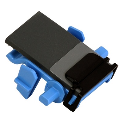
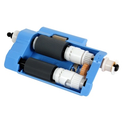
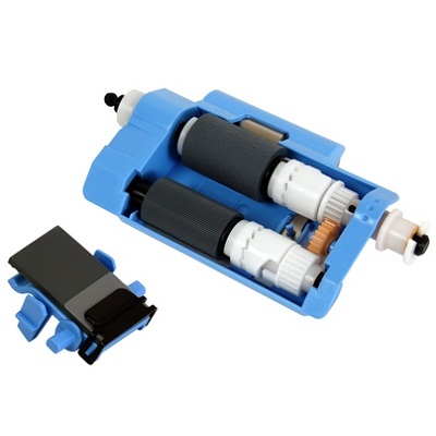
331 MULTI FEED PAPER PICK-UP ASSY
460 LASER SCANNER ASSEMBLY
930 DC CONTROLLER PCB ASSEMBLY
810 FIXING ASSEMBLY, FX-201
B13 PAPER FEED DRIVE ASSEMBLY
108 MACHINE REAR PLATE 1
T21 SPEAKER (FAX model)
B11 AUTO DOCUMENT FEEDER ASSEMBLY 2
102 DOOR ASSEMBLY, RIGHT
109 MACHINE REAR PLATE 2
105 INTERNAL COMPONENTS 3
350 PAPER DELIVERY, REVERSE ASSY
772 CONTAINER, WASTE TONER, WT-201
106 INTERNAL COMPONENTS 4
B12 FEEDER COVER ASSEMBLY
103 INTERNAL COMPONENTS 1
280 FIXING DRIVE ASSEMBLY
260 PAPER PICK-UP DRIVE ASSEMBLY
101 DOOR ASSEMBLY, FRONT
300 CASSETTE
330 MULTI FEED TRAY ASSEMBLY
900 CONTROLLER BOX ASSEMBLY
B01 ADF MAINTENANCE KIT
910 POWER SUPPLY ASSEMBLY
B10 READER, ADF ASSEMBLY
771 INTERNAL COVER ASSEMBLY
T20 FAX ASSEMBLY (FAX model)
107 INTERNAL COMPONENTS 5
332 DUPLEXING GUIDE ASSEMBLY
Детали B01 ADF MAINTENANCE KIT

| Деталь: | LEVER, REMNANT DETECT |
| Парткод: | FE3-4041-000 |
| Деталь: | IC, PHOTO INTERRUPTER |
| Парткод: | WG8-5935-000 |
| Деталь: | PICK-UP LIFTER DRIVE ASSY |
| Парткод: | FM0-0018-000 |
| Деталь: | RAIL, I.T.B., FRONT |
| Парткод: | FM0-0035-000 |
| Деталь: | RAIL, I.T.B., REAR |
| Парткод: | FM0-0036-000 |
| Деталь: | HOLDER, FIXING LOCK |
| Парткод: | FM0-0074-000 |
| Деталь: | RAIL, PROCESS CARTRIDGE, RIGHT |
| Парткод: | FC0-6502-000 |
| Деталь: | REGISTRATION SENSOR ASSEMBLY |
| Парткод: | FM1-F727-000 |
| Деталь: | SCREW,RS,M3X8 |
| Парткод: | XA9-1386-000 |
| Деталь: | SHEET, PROTECTION |
| Парткод: | FL0-3763-000 |
| Деталь: | HOLDER, FIXING, REAR |
| Парткод: | FM4-9911-000 |
| Деталь: | HOLDER, FIXING, FRONT |
| Парткод: | FM4-9910-000 |
| Деталь: | PLATE ASSEMBLY |
| Парткод: | FM1-C347-000 |
| Деталь: | CONNECTING CABLE ASSEMBLY |
| Парткод: | FM1-C324-000 |
| Деталь: | FIXING GROUNDING ASSEMBLY |
| Парткод: | FM1-B572-000 |
| Деталь: | INTERNAL COMPONENTS 2 |
| Парткод: | NPN |
| Деталь: | COVER, READER, FRONT |
| Парткод: | FM1-G152-000 |
| Деталь: | LABEL, BLACK LINE, CLEANING |
| Парткод: | FU2-0805-000 |
| Деталь: | LABEL, COPY INHIBITED |
| Парткод: | FU7-8085-000 |
| Деталь: | LABEL, COPY INHIBITED |
| Парткод: | FU7-8086-000 |
| Деталь: | LABEL, COPY INHIBITED |
| Парткод: | FU7-8087-000 |
| Деталь: | LABEL, COPY INHIBITED |
| Парткод: | FU7-8227-000 |
| Деталь: | LABEL, COPY INHIBITED |
| Парткод: | FU7-8228-000 |
| Деталь: | LABEL, COPY INHIBITED |
| Парткод: | FU7-8229-000 |
| Деталь: | LABEL, COPY INHIBITED |
| Парткод: | FU7-8230-000 |
| Деталь: | LABEL, COPY INHIBITED |
| Парткод: | FU7-8231-000 |
| Деталь: | CAP |
| Парткод: | FC0-0695-000 |
| Деталь: | COVER, LOWER |
| Парткод: | FC0-5542-000 |
| Деталь: | GUIDE, CABLE |
| Парткод: | FC0-5547-000 |
| Деталь: | COVER, MOTOR |
| Парткод: | FC0-5548-000 |
| Деталь: | STOPPER, BELT |
| Парткод: | FC0-5550-000 |
| Деталь: | BELT, TIMING, COGGED |
| Парткод: | FC0-5553-000 |
| Деталь: | SPACER, CONTACT IMAGE SENSOR |
| Парткод: | FE3-6571-000 |
| Деталь: | SPACER, CONTACT IMAGE SENSOR |
| Парткод: | FC0-5554-000 |
| Деталь: | SPACER, CONTACT IMAGE SENSOR |
| Парткод: | FE3-6570-000 |
| Деталь: | HOLDER, CONTACT IMAGE SENSOR |
| Парткод: | FC0-5555-000 |
| Деталь: | BUSHING |
| Парткод: | FC0-5557-000 |
| Деталь: | COVER, READER, REAR, 1 |
| Парткод: | FL0-3924-000 |
| Деталь: | PULLEY, IDLER |
| Парткод: | FC0-5650-000 |
| Деталь: | COVER, READER, FRONT LOWER |
| Парткод: | FC0-5651-000 |
| Деталь: | SCREW,RS,M3X8 |
| Парткод: | XA9-1386-000 |
| Деталь: | HOLDER, PULLEY, IDLER |
| Парткод: | FC0-5552-000 |
| Деталь: | MOTOR, STEPPING |
| Парткод: | FK3-3035-000 |
| Деталь: | CONTACT IMAGE SENSOR ASSEMBLY |
| Парткод: | FM1-H164-000 |
| Деталь: | CONTACT IMAGE SENSOR ASSEMBLY |
| Парткод: | FM1-H163-000 |
| Деталь: | CABLE, FLAT |
| Парткод: | FK3-3038-000 |
| Деталь: | SCREW, RS, M3X8 |
| Парткод: | XA9-1449-000 |
| Деталь: | CABLE, READER MAIN |
| Парткод: | FM1-C984-000 |
| Деталь: | CABLE, HOME POSITION SENSOR |
| Парткод: | FM1-C987-000 |
| Деталь: | FOOT, READER |
| Парткод: | FL0-2019-000 |
| Деталь: | SHEET, INSULATING |
| Парткод: | FL3-6317-000 |
| Деталь: | CONNECTOR, SNAP TIGHT, BK |
| Парткод: | VS1-7207-003 |
| Деталь: | SPRING, COMPRESSION |
| Парткод: | FU6-2873-000 |
| Деталь: | GEAR, 85T/20T |
| Парткод: | FU9-0581-000 |
| Деталь: | SPRING, COMPRESSION |
| Парткод: | FU9-2023-000 |
| Деталь: | CONNECTOR, SNAP TIGHT, BK |
| Парткод: | VS1-7177-004 |
| Деталь: | IC, PHOTO INTERRUPTER |
| Парткод: | WG8-5935-000 |
| Деталь: | READER ASSEMBLY |
| Парткод: | NPN |
| Деталь: | INTER. TRANSFER BELT ASSY |
| Парткод: | FM1-A153-000 |
| Деталь: | FAN |
| Парткод: | FK2-3679-000 |
| Деталь: | CARTRIDGE AIR INTAKE FAN ASSY |
| Парткод: | NPN |
| Деталь: | IC, PHOTO INTERRUPTER |
| Парткод: | WG8-5935-000 |
| Деталь: | BOTTLE MOUNT ASSEMBLY |
| Парткод: | FM0-0002-000 |
| Деталь: | FAN |
| Парткод: | FK2-3679-000 |
| Деталь: | CONNECTOR, SNAP TIGHT, BK |
| Парткод: | VS1-7440-003 |
| Деталь: | DELIVERY COOLING FAN ASSEMBLY |
| Парткод: | NPN |
| Деталь: | SHAFT |
| Парткод: | FC0-5875-000 |
| Деталь: | BUSHING |
| Парткод: | FC0-5876-000 |
| Деталь: | BUSHING |
| Парткод: | FC0-5888-000 |
| Деталь: | SHAFT |
| Парткод: | FC0-5935-000 |
| Деталь: | PANEL, RIGHT DOOR, FRONT |
| Парткод: | FC0-5938-000 |
| Деталь: | PANEL, CABLE |
| Парткод: | FC0-5941-000 |
| Деталь: | FLAG, DUPLEXING SENSOR |
| Парткод: | FC0-5943-000 |
| Деталь: | COVER, BLANKING |
| Парткод: | FC0-6612-000 |
| Деталь: | LINK, RELEASE |
| Парткод: | FC0-7446-000 |
| Деталь: | GUIDE, LOCK, FRONT |
| Парткод: | FC0-7535-000 |
| Деталь: | GUIDE, LOCK, REAR |
| Парткод: | FC0-7536-000 |
| Деталь: | SUPPORT, ROLLER |
| Парткод: | FE3-1547-000 |
| Деталь: | BUSHING |
| Парткод: | FE3-1617-000 |
| Деталь: | COVER, PAPER FEED ROLLER |
| Парткод: | FE3-1641-000 |
| Деталь: | HOLDER, MULTI FEED SWING |
| Парткод: | FE3-1760-000 |
| Деталь: | SPRING, TORSION |
| Парткод: | FE3-2409-000 |
| Деталь: | SHAFT |
| Парткод: | FE3-3585-000 |
| Деталь: | SHAFT |
| Парткод: | FE3-3594-000 |
| Деталь: | GUIDE, SHUTTER LINK |
| Парткод: | FE3-4759-000 |
| Деталь: | SHUTTER, PAPER PICK-UP |
| Парткод: | FE3-4760-000 |
| Деталь: | LOCK, SHUTTER |
| Парткод: | FE3-4761-000 |
| Деталь: | LEVER, SHUTTER LINK |
| Парткод: | FE3-4762-000 |
| Деталь: | GEAR, 18T |
| Парткод: | FE3-4764-000 |
| Деталь: | BOSS, TRAY |
| Парткод: | FE3-4765-000 |
| Деталь: | SHEET, FLAG SILENCER |
| Парткод: | FL0-1010-000 |
| Деталь: | CABLE, FAN GROUNDING, RIGHT |
| Парткод: | FE3-6116-000 |
| Деталь: | CABLE, GROUNDING, RIGHT |
| Парткод: | FE3-6117-000 |
| Деталь: | FAN |
| Парткод: | FK2-0472-010 |
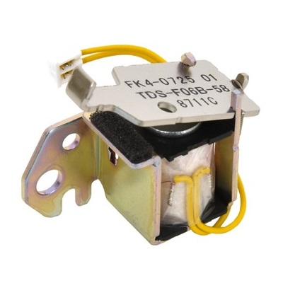
| Деталь: | SOLENOID |
| Парткод: | FK4-0725-000 |
| Цена: | 1 400 ₽ |
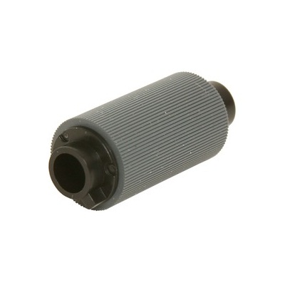
| Деталь: | ROLLER, PAPER PICK-UP&FEED |
| Парткод: | FL0-1011-000 |
| Деталь: | CLUTCH, ONE-WAY |
| Парткод: | FL0-1361-000 |
| Деталь: | BUSHING |
| Парткод: | FE3-5654-000 |
| Деталь: | ROLLER, DUPLEXING FEED DOOR |
| Парткод: | FL3-6443-000 |
| Деталь: | HOOK ASSEMBLY, RIGHT DUPLEXING |
| Парткод: | FM1-B549-000 |
| Деталь: | INNER GUIDE ASSEMBLY RIGHT |
| Парткод: | FM1-B552-000 |
| Деталь: | INNER DOOR ASSEMBLY |
| Парткод: | FM1-B553-000 |
| Деталь: | 2ND TRNSFR. OUTER GUIDE ASSY |
| Парткод: | FM1-B554-000 |
| Деталь: | SENSOR UNIT, LOOP |
| Парткод: | FM1-B555-000 |
| Деталь: | IC, PHOTO INTERRUPTER |
| Парткод: | WG8-5935-000 |
| Деталь: | ROLLER, 2ND TRNSFR. OUTER |
| Парткод: | FC0-5848-000 |
| Деталь: | HOLDER, BUSHING, FRONT |
| Парткод: | FC0-5861-000 |
| Деталь: | HOLDER, BUSHING, REAR |
| Парткод: | FC0-5862-000 |
| Деталь: | 2ND TRNSFR. OUTER ROLLER ASSY |
| Парткод: | FM1-C318-000 |
| Деталь: | BEARING, BALL, L-1060ZZ |
| Парткод: | XG9-0783-000 |
| Деталь: | SPRING, TORSION |
| Парткод: | FU2-0192-000 |
| Деталь: | GEAR, 16T |
| Парткод: | FU2-0197-000 |
| Деталь: | GEAR, 27T |
| Парткод: | FU2-0198-000 |
| Деталь: | GEAR, 14T |
| Парткод: | FU2-0257-000 |
| Деталь: | GEAR, 18T |
| Парткод: | FU2-0259-000 |
| Деталь: | GEAR, 17T |
| Парткод: | FU2-0358-000 |
| Деталь: | GEAR, 19T |
| Парткод: | FU9-0662-000 |
| Деталь: | GEAR, 25T |
| Парткод: | FU9-0663-000 |
| Деталь: | GEAR, 42T/21T |
| Парткод: | FU9-0665-000 |
| Деталь: | GEAR, 23T |
| Парткод: | FU9-0666-000 |
| Деталь: | GEAR, 28T |
| Парткод: | FU9-0667-000 |
| Деталь: | GEAR, 14T |
| Парткод: | FU9-0668-000 |
| Деталь: | GEAR, 14T |
| Парткод: | FU9-0670-000 |
| Деталь: | SPRING, COMPRESSION |
| Парткод: | FU9-2068-000 |
| Деталь: | SPRING, TORSION |
| Парткод: | FU9-2069-000 |
| Деталь: | SPRING, TORSION |
| Парткод: | FU9-2070-000 |
| Деталь: | SPRING, TORSION |
| Парткод: | FU9-2071-000 |
| Деталь: | SPRING, TORSION |
| Парткод: | FU9-2112-000 |
| Деталь: | SPRING, TORSION |
| Парткод: | FU9-2224-000 |
| Деталь: | CONNECTOR, SNAP TIGHT, BK |
| Парткод: | VS1-7177-002 |
| Деталь: | CONNECTOR, SNAP TIGHT, BK |
| Парткод: | VS1-7207-003 |
| Деталь: | CONNECTOR, SNAP TIGHT, BK |
| Парткод: | VS1-7207-006 |
| Деталь: | CONNECTOR, SNAP TIGHT, BK |
| Парткод: | VS1-7177-003 |
| Деталь: | CABLE, DOOR, RIGHT |
| Парткод: | FM1-A825-000 |
| Деталь: | CABLE, DOOR FAN, RIGHT |
| Парткод: | FM1-A827-000 |
| Деталь: | COVER, ROLLER |
| Парткод: | FC0-6614-000 |
| Деталь: | COVER, ROLLER |
| Парткод: | FE3-0389-000 |
| Деталь: | SHEET, LIMIT |
| Парткод: | FE4-4660-000 |
| Деталь: | DOOR ASSEMBLY, RIGHT |
| Парткод: | FM0-0020-000 |
| Деталь: | SHAFT, CAM |
| Парткод: | FC0-5587-000 |
| Деталь: | CAM, HAND |
| Парткод: | FC0-5588-000 |
| Деталь: | LEVER, ROLLER ESTRANGEMENT |
| Парткод: | FC0-5589-000 |
| Деталь: | COVER, COPYBOARD |
| Парткод: | FC0-5591-000 |
| Деталь: | COVER, ADF, REAR |
| Парткод: | FC0-5593-000 |
| Деталь: | STOPPER, DOCUMENT |
| Парткод: | FC0-5629-000 |
| Деталь: | COVER, SEPARATION SPRING |
| Парткод: | FC0-5634-000 |
| Деталь: | STOPPER, RATCHET SPRING |
| Парткод: | FE4-1402-000 |
| Деталь: | RATCHET, PAPER FEED ROLLER |
| Парткод: | FC7-6052-010 |
| Деталь: | ROLLER, PAPER DELIVERY |
| Парткод: | FE3-8381-000 |
| Деталь: | SPRING, TORSION |
| Парткод: | FC7-6303-000 |
| Деталь: | SHAFT |
| Парткод: | FE3-6504-000 |
| Деталь: | ROLLER, PAPER DELIVERY |
| Парткод: | FL0-1104-000 |
| Деталь: | PANEL, COPYBOARD |
| Парткод: | FL0-1105-000 |
| Деталь: | DAMPER, MAIN FRAME |
| Парткод: | FL0-2013-000 |
| Деталь: | GUIDE, FEED |
| Парткод: | FL0-2020-000 |
| Деталь: | GUIDE, PAPER DELIVERY |
| Парткод: | FL0-2021-000 |
| Деталь: | HINGE, ADF, LEFT |
| Парткод: | FL3-1430-000 |
| Цена: | 1 100 ₽ |
| Деталь: | ARM, PAPER FEED SWING |
| Парткод: | FL3-6308-000 |
| Деталь: | ARM, SEPARATION SWING |
| Парткод: | FL3-6309-000 |
| Деталь: | ROLLER, DF FEED |
| Парткод: | FL3-6311-000 |
| Деталь: | HINGE, ADF, RIGHT |
| Парткод: | FL3-6313-000 |
| Деталь: | SHEET, GUIDE, LOWER |
| Парткод: | FL3-6314-000 |
| Деталь: | PAD, DAMPER |
| Парткод: | FL3-6320-000 |
| Деталь: | ROLLER, PAPER FEED |
| Парткод: | FE3-8290-000 |
| Деталь: | CABLE, ADF DETECT |
| Парткод: | FM1-C985-000 |
| Деталь: | CABLE, ADF - DES |
| Парткод: | FM1-C986-000 |
| Деталь: | ADF BASE ASSEMBLY |
| Парткод: | FM4-9855-000 |
| Деталь: | DOCUMENT TRAY ASSEMBLY |
| Парткод: | FM4-9856-000 |
| Деталь: | SEPARATION PAD ASSEMBLY |
| Парткод: | FM4-9857-000 |
| Цена: | 4 800 ₽ |
| Деталь: | GUIDE, UPPER |
| Парткод: | FM4-9858-000 |
| Деталь: | SPRING, TENSION |
| Парткод: | FU6-2999-000 |
| Деталь: | BUSHING |
| Парткод: | FU5-1748-000 |
| Деталь: | ROLLER, AUXILIARY |
| Парткод: | FE3-8380-000 |
| Деталь: | GEAR, 21T |
| Парткод: | FU8-0128-000 |
| Деталь: | SPRING, COMPRESSION |
| Парткод: | FE4-0007-000 |
| Деталь: | GEAR, 18T |
| Парткод: | FU9-0237-000 |
| Деталь: | GEAR, 43T |
| Парткод: | FU9-0589-000 |
| Деталь: | GEAR, 43T |
| Парткод: | FU9-0590-000 |
| Деталь: | GEAR, 41T |
| Парткод: | FU9-0591-000 |
| Деталь: | GEAR, 57T/21T |
| Парткод: | FU9-0592-000 |
| Деталь: | GEAR, 20T |
| Парткод: | FU9-0594-000 |
| Деталь: | SPRING, TORSION |
| Парткод: | FU9-2005-000 |
| Деталь: | SPRING, COMPRESSION |
| Парткод: | FU9-2007-000 |
| Деталь: | SPRING, COMPRESSION |
| Парткод: | FU9-2008-000 |
| Деталь: | SPRING, COMPRESSION |
| Парткод: | FU9-2009-000 |
| Деталь: | SPRING, TENSION |
| Парткод: | FU9-2010-000 |
| Деталь: | SPRING, TORSION |
| Парткод: | FU9-2011-000 |
| Деталь: | SPRING, TENSION |
| Парткод: | FU9-2015-000 |
| Деталь: | SPRING, TENSION |
| Парткод: | FU9-2016-000 |
| Деталь: | SPRING, TENSION |
| Парткод: | FU9-2017-000 |
| Деталь: | SPRING, TORSION |
| Парткод: | FU9-2019-000 |
| Деталь: | SPRING, COMPRESSION |
| Парткод: | FU9-2020-000 |
| Деталь: | IC, PHOTO INTERRUPTER |
| Парткод: | WG8-5935-000 |
| Деталь: | LABEL, PROHIBITION DOCUMENT |
| Парткод: | FE3-9826-000 |
| Деталь: | LABEL, CLEANING INSTRUCTION |
| Парткод: | FE3-9827-000 |
| Деталь: | HOLDER, LEVER |
| Парткод: | FC0-5574-000 |
| Деталь: | LEVER, DRIVE RELEASE |
| Парткод: | FE3-7698-000 |
| Деталь: | RING, C,EXTERNAL |
| Парткод: | FE3-7699-000 |
| Деталь: | BUSHING |
| Парткод: | FE3-8298-000 |
| Деталь: | CUSHION, WHITE SHEET |
| Парткод: | FL3-6315-000 |
| Деталь: | CONNECTOR, SNAP TIGHT, BK |
| Парткод: | VS1-7177-002 |
| Деталь: | CONNECTOR, SNAP TIGHT, BK |
| Парткод: | VS1-7207-006 |
| Деталь: | CONNECTOR, SNAP TIGHT, BK |
| Парткод: | VS1-7207-004 |
| Деталь: | AUTO DOCUMENT FEEDER ASSEMBLY |
| Парткод: | FM4-9849-000 |
| Деталь: | DIAL, CONTRAST |
| Парткод: | FC0-3267-000 |
| Деталь: | PLATE, GROUNDING |
| Парткод: | FC0-8988-000 |
| Деталь: | COVER, LAMP |
| Парткод: | FE2-1544-000 |
| Деталь: | CROSSMEMBER, CONTROL PANEL |
| Парткод: | FE2-1556-000 |
| Деталь: | PLATE, DIAL, 2 |
| Парткод: | FE2-1584-000 |
| Деталь: | PLATE, DIAL, 1 |
| Парткод: | FE2-1585-000 |
| Деталь: | COVER, LCD |
| Парткод: | FE3-1731-000 |
| Деталь: | SHEET, TOUCH PANEL |
| Парткод: | FE3-1742-000 |
| Деталь: | KEY TOP, VOLUME |
| Парткод: | FE3-1744-000 |
| Деталь: | KEY TOP, STOP |
| Парткод: | FE3-1745-000 |
| Деталь: | KEY TOP, ENERGY SAVER |
| Парткод: | FE3-1746-000 |
| Деталь: | KEY TOP, TEN |
| Парткод: | FE3-1747-000 |
| Деталь: | KEY TOP, RESET |
| Парткод: | FE3-1748-000 |
| Деталь: | PANEL, TOUCH |
| Парткод: | FK4-0092-000 |
| Деталь: | CABLE, FLAT |
| Парткод: | FK4-0922-000 |
| Деталь: | PEN, TOUCH PANEL |
| Парткод: | FL0-0287-000 |
| Деталь: | KEY, START |
| Парткод: | FL3-6538-000 |
| Деталь: | PANEL, CONTROL, FRONT UPPER |
| Парткод: | FL3-6540-000 |
| Деталь: | PANEL, CONTROL, FRONT UPPER |
| Парткод: | FL3-6544-000 |
| Деталь: | HINGE, CONTROL ASSEMBLY, LEFT |
| Парткод: | FM0-0076-000 |
| Деталь: | HINGE, CONTROL ASSEMBLY, RIGHT |
| Парткод: | FM0-0077-000 |
| Деталь: | CONTROL PANEL CPU PCB ASSEMBLY |
| Парткод: | FM1-D941-000 |
| Деталь: | CONTROL PANEL KEY PCB ASSEMBLY |
| Парткод: | FM1-D942-000 |
| Деталь: | COVER, FRONT |
| Парткод: | FE2-1554-000 |
| Деталь: | LCD UNIT |
| Парткод: | FM1-A214-000 |
| Деталь: | SUPPORT |
| Парткод: | FC5-7863-000 |
| Деталь: | CONTROL PANEL ASSEMBLY |
| Парткод: | FM4-9939-000 |
| Деталь: | CONTROL PANEL ASSEMBLY |
| Парткод: | FM0-0051-000 |
| Деталь: | CONTROL PANEL ASSEMBLY |
| Парткод: | FM4-9941-000 |
| Деталь: | CONTROL PANEL ASSEMBLY |
| Парткод: | FM4-9931-000 |
| Деталь: | CONTROL PANEL ASSEMBLY |
| Парткод: | FM4-9940-000 |
| Деталь: | CONTROL PANEL ASSEMBLY |
| Парткод: | FM4-9933-000 |
| Деталь: | CONTROL PANEL ASSEMBLY |
| Парткод: | FM4-9932-000 |
| Деталь: | COVER, CONTROL PANEL ASSEMBLY |
| Парткод: | FM0-0058-000 |
| Деталь: | TRAY, PAPER DELIVERY |
| Парткод: | FM1-C319-000 |
| Деталь: | COVER, UPPER |
| Парткод: | FM1-C320-000 |
| Деталь: | COVER, REAR UPPER |
| Парткод: | FM1-C321-000 |
| Деталь: | COVER, RIGHT LOWER |
| Парткод: | FC0-7213-000 |
| Деталь: | COVER, ENV. HEATER SWITCH |
| Парткод: | FC8-4137-000 |
| Деталь: | COVER, REAR, 2 |
| Парткод: | FC0-7575-000 |
| Деталь: | SEAL, BLANKING |
| Парткод: | FC9-7297-000 |
| Деталь: | PANEL, CONTROL HINGE, REAR |
| Парткод: | FE2-1566-000 |
| Деталь: | COVER, PAPER DELIVERY |
| Парткод: | FE3-3748-000 |
| Деталь: | COVER, RIGHT FRONT |
| Парткод: | FL3-6516-000 |
| Деталь: | COVER, RIGHT REAR |
| Парткод: | FL3-6518-000 |
| Деталь: | COVER, RIGHT UPPER |
| Парткод: | FL3-6517-000 |
| Деталь: | EMBLEM |
| Парткод: | FL3-1185-000 |
| Деталь: | COVER, UPPER, LEFT |
| Парткод: | FC0-7567-000 |
| Деталь: | COVER, DEVICE PORT |
| Парткод: | FC0-7570-000 |
| Деталь: | COVER, FAX CONNECTOR |
| Парткод: | FC8-8346-000 |
| Деталь: | COVER, LEFT LOWER |
| Парткод: | FL0-3939-000 |
| Деталь: | LABEL, TONER |
| Парткод: | FC0-7790-000 |
| Деталь: | LABEL, TONER |
| Парткод: | FC0-7791-000 |
| Деталь: | LABEL, TONER |
| Парткод: | FC0-7792-000 |
| Деталь: | SHEET, PAPER DELIVERY TRAY, 2 |
| Парткод: | FL0-1008-000 |
| Деталь: | COVER, REAR, 1 |
| Парткод: | FC0-7171-000 |
| Деталь: | COVER, HEATER, ENVIRONMENT |
| Парткод: | FC0-7685-000 |
| Деталь: | LABEL, MODULAR |
| Парткод: | FC0-7730-000 |
| Деталь: | LABEL, MODULAR |
| Парткод: | FC0-7731-000 |
| Деталь: | LABEL, GROUNDING CAUTION |
| Парткод: | FU7-8521-000 |
| Деталь: | HOLDER, SERVICE BOOK |
| Парткод: | FC9-9069-000 |
| Деталь: | DAMPER UNIT, AIR |
| Парткод: | FC7-6142-000 |
| Деталь: | EXTERNAL COVERS, PANELS, ETC. |
| Парткод: | NPN |
| Деталь: | MOTOR, DC |
| Парткод: | FL0-1543-000 |
| Деталь: | MOTOR, DC |
| Парткод: | FL0-1544-000 |
| Деталь: | MAIN DRIVE ASSEMBLY |
| Парткод: | FM0-0040-000 |
| Деталь: | BOTTLE DRIVE ASSEMBLY |
| Парткод: | FM0-0007-000 |
| Деталь: | HOPPER ASSEMBLY |
| Парткод: | FM0-0006-000 |
| Деталь: | BUSHING |
| Парткод: | FC0-5876-000 |
| Деталь: | BUSHING |
| Парткод: | FC0-5888-000 |
| Деталь: | CABLE, REG. GROUNDING |
| Парткод: | FC0-6968-000 |
| Деталь: | ROLLER, REGISTRATION |
| Парткод: | FC0-6979-000 |
| Деталь: | BLOCK, REGIST. PRESSURE |
| Парткод: | FC0-7174-000 |
| Деталь: | LEVER, PAPER PICK-UP SENSOR |
| Парткод: | FC0-7204-000 |
| Деталь: | SPRING, TORSION |
| Парткод: | FC0-7205-000 |
| Деталь: | SPRING, TORSION |
| Парткод: | FC0-7211-000 |
| Деталь: | FLAG, REGISTRATION SENSOR |
| Парткод: | FC0-7218-000 |
| Деталь: | LEVER, PAPER DETECT |
| Парткод: | FC0-7670-000 |
| Деталь: | BUSHING |
| Парткод: | FC6-1353-000 |
| Деталь: | LEVER, PAPER PICK-UP LATCH |
| Парткод: | FE3-1585-000 |
| Деталь: | ARM, PAPER PICK-UP |
| Парткод: | FE3-1602-000 |
| Деталь: | BUSHING |
| Парткод: | FE3-1617-000 |
| Деталь: | SPRING, TORSION |
| Парткод: | FE3-1618-000 |
| Деталь: | ROLLER, REGISTRATION DRIVEN |
| Парткод: | FE3-9592-000 |
| Деталь: | LIMITER, TORQUE |
| Парткод: | FE3-4860-000 |
| Деталь: | GEAR, 23T |
| Парткод: | FE3-4861-000 |
| Деталь: | SPRING, GROUNDING |
| Парткод: | FE3-5614-000 |
| Деталь: | GUIDE, PRE-REGISTRATION |
| Парткод: | FE3-6112-000 |
| Деталь: | BUSHING |
| Парткод: | FE3-6113-000 |
| Деталь: | BUSHING |
| Парткод: | FE3-6114-000 |
| Деталь: | SPRING, GROUNDING |
| Парткод: | FE3-6119-000 |
| Деталь: | ROLLER, EXTRACTION |
| Парткод: | FL0-1834-000 |
| Деталь: | ROLLER, PAPER PICK-UP&FEED |
| Парткод: | FL0-1011-000 |
| Деталь: | ONE-WAY GEAR ASSEMBLY |
| Парткод: | FL0-1570-000 |
| Деталь: | SHEET, SEPARATION ROLLER GUIDE |
| Парткод: | FL0-2588-000 |
| Деталь: | ONE-WAY GEAR ASSEMBLY |
| Парткод: | FM0-0030-000 |
| Деталь: | REG. SWING HOLDER ASSEMBLY |
| Парткод: | FM1-B297-000 |
| Деталь: | SEPARATION FRAME ASSEMBLY |
| Парткод: | FM1-B557-000 |
| Деталь: | BUSHING |
| Парткод: | FS1-1205-000 |
| Деталь: | SPRING, TENSION |
| Парткод: | FU2-0234-000 |
| Деталь: | GEAR, 23T |
| Парткод: | FU2-0247-000 |
| Деталь: | GEAR, 22T |
| Парткод: | FU2-0248-000 |
| Деталь: | SPRING, TORSION |
| Парткод: | FU2-0284-000 |
| Деталь: | GEAR, 32T |
| Парткод: | FU2-0287-000 |
| Деталь: | GEAR, 27T/21T |
| Парткод: | FU2-0294-000 |
| Деталь: | GEAR, 17T |
| Парткод: | FU2-0295-000 |
| Деталь: | GEAR, 24T/20T |
| Парткод: | FU2-0297-000 |
| Деталь: | GEAR, 23T |
| Парткод: | FU2-0298-000 |
| Деталь: | HOLDER, REGISTRATION SWING |
| Парткод: | FU2-0578-000 |
| Деталь: | GEAR, 18T |
| Парткод: | FU8-0085-000 |
| Деталь: | GEAR, 17T |
| Парткод: | FU9-0675-000 |
| Деталь: | SPRING, TORSION |
| Парткод: | FU9-2094-000 |
| Деталь: | IC, PHOTO INTERRUPTER |
| Парткод: | WG8-5935-000 |
| Деталь: | ROLLER, REGISTRATION DRIVEN |
| Парткод: | FE3-9593-000 |
| Деталь: | ROLLER, SEPARATION |
| Парткод: | FL0-1674-000 |
| Цена: | 5 000 ₽ |
| Деталь: | ONE-WAY CLUTCH ASSEMBLY |
| Парткод: | FL0-1515-000 |
| Деталь: | SPRING, TENSION |
| Парткод: | FU2-0236-000 |
| Деталь: | SPRING, TORSION |
| Парткод: | FE3-3935-000 |
| Деталь: | RING, RESIN, RETAINING |
| Парткод: | FC6-3002-000 |
| Деталь: | SHEET, GAP |
| Парткод: | FL0-4485-000 |
| Деталь: | RESIST/PAPER PICK-UP ASSY |
| Парткод: | FM0-0029-000 |
| Деталь: | FAN |
| Парткод: | FK4-0815-000 |
| Деталь: | CONNECTOR, SNAP TIGHT, BK |
| Парткод: | VS1-7177-003 |
| Деталь: | POWER SUPPLY FAN ASSEMBLY |
| Парткод: | NPN |
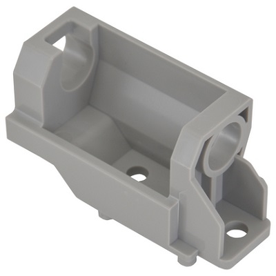
| Деталь: | HOLDER, PAPER FEED ROLLER |
| Парткод: | FC0-6637-000 |
| Деталь: | LINK, RELEASE |
| Парткод: | FC0-7447-000 |
| Деталь: | SHAFT, ROLLER |
| Парткод: | FE3-0387-000 |
| Деталь: | LEVER, PAPER YES/NO SENSING |
| Парткод: | FE3-1642-000 |
| Деталь: | CAM, ROLLER ESTRANGEMENT |
| Парткод: | FE3-3589-000 |
| Деталь: | GEAR, 33T |
| Парткод: | FU6-1304-000 |
| Деталь: | SPRING, TENSION |
| Парткод: | FU9-2088-000 |
| Деталь: | SPRING, TORSION |
| Парткод: | FU9-2091-000 |
| Деталь: | IC, PHOTO INTERRUPTER |
| Парткод: | WG8-5935-000 |
| Деталь: | LIMITER, TORQUE |
| Парткод: | FE3-4860-000 |
| Деталь: | ROLLER, SEPARATION |
| Парткод: | FL0-1674-000 |
| Цена: | 5 000 ₽ |
| Деталь: | ROLLER, ESTRANGEMENT CAM |
| Парткод: | FE3-5655-000 |
| Деталь: | MULTI FEED PAPER PICK-UP ASSY |
| Парткод: | FM1-B308-000 |
| Деталь: | DUST-PROOF SHUTTER ASSEMBLY |
| Парткод: | FM0-0031-000 |
| Деталь: | CABLE, LASER SCANNER |
| Парткод: | FM1-A823-000 |
| Деталь: | SPRING, TENSION |
| Парткод: | FU9-2181-000 |
| Деталь: | LASER SCANNER ASSEMBLY |
| Парткод: | FM0-0144-000 |
| Деталь: | LASER SCANNER ASSEMBLY |
| Парткод: | NPN |
| Деталь: | DC CONTROLLER PCB ASSEMBLY |
| Парткод: | FM1-C743-000 |
| Деталь: | CABLE, FLAT |
| Парткод: | FK4-0645-000 |
| Деталь: | DC CONTROLLER PCB ASSEMBLY |
| Парткод: | NPN |
| Деталь: | ROLLER, PRESSURE |
| Парткод: | FC0-6078-000 |
| Деталь: | HOLDER, BEARING |
| Парткод: | FC0-6079-000 |
| Деталь: | CAM, PRESSURE RELEASE |
| Парткод: | FC0-6086-000 |
| Деталь: | PLATE, PRESSURE, REAR |
| Парткод: | FC0-6088-000 |
| Деталь: | FLAG, PAPER DELIVERY SENSOR |
| Парткод: | FC0-6092-000 |
| Деталь: | PLATE, PRESSURE, LEFT |
| Парткод: | FC0-6131-000 |
| Деталь: | LOCK, SHUTTER, FRONT |
| Парткод: | FC0-6156-000 |
| Деталь: | LOCK, SPRING, FRONT |
| Парткод: | FC0-6157-000 |
| Деталь: | FIXING FILM ASSEMBLY |
| Парткод: | FM0-0080-000 |
| Деталь: | FIXING FILM ASSEMBLY |
| Парткод: | FM1-C340-000 |
| Деталь: | CABLE, FIXING ASSEMBLY |
| Парткод: | FM1-A802-000 |
| Деталь: | FIXING LOCK ASSEMBLY |
| Парткод: | FM1-C746-000 |
| Деталь: | SPRING, COMPRESSION |
| Парткод: | FU2-0230-000 |
| Деталь: | GEAR, 29T |
| Парткод: | FU9-0610-000 |
| Деталь: | GEAR, 24T |
| Парткод: | FU9-0611-000 |
| Деталь: | GEAR, 30T |
| Парткод: | FU9-0612-000 |
| Деталь: | SPRING, TENSION |
| Парткод: | FU9-2104-000 |
| Деталь: | SPRING, TORSION |
| Парткод: | FU9-2105-000 |
| Деталь: | SPRING, TORSION |
| Парткод: | FU9-2106-000 |
| Деталь: | SPRING, TORSION |
| Парткод: | FU9-2111-000 |
| Деталь: | IC, PHOTO INTERRUPTER |
| Парткод: | WG8-5935-000 |
| Деталь: | IC, PHOTO INTERRUPTER |
| Парткод: | WG8-5783-000 |
| Деталь: | BEARING, BALL, L-1260ZZR |
| Парткод: | XG9-0831-000 |
| Деталь: | CONNECTOR, SNAP TIGHT, BK |
| Парткод: | VS1-7177-002 |
| Деталь: | CONNECTOR, SNAP TIGHT, BK |
| Парткод: | VS1-7177-006 |
| Деталь: | FIXING ASSEMBLY, FX-201 |
| Парткод: | FM0-0072-000 |
| Деталь: | FIXING ASSEMBLY, FX-201 |
| Парткод: | FM0-0073-000 |
| Деталь: | GEAR, 29T |
| Парткод: | FC0-5622-000 |
| Деталь: | STOPPER, CAM |
| Парткод: | FC0-5623-000 |
| Деталь: | SOLENOID |
| Парткод: | FK2-0408-010 |
| Деталь: | MOTOR, STEPPING |
| Парткод: | FK3-2024-000 |
| Деталь: | GEAR, 47T/20T |
| Парткод: | FU9-0588-000 |
| Деталь: | GEAR, 16T |
| Парткод: | FU9-0595-000 |
| Деталь: | PULLEY |
| Парткод: | FU9-0596-000 |
| Деталь: | GEAR, 52T |
| Парткод: | FU9-0597-000 |
| Деталь: | GEAR, 55T |
| Парткод: | FU9-0598-000 |
| Деталь: | BELT, TIMING, COGGED |
| Парткод: | XF2-1611-830 |
| Деталь: | PAPER FEED DRIVE ASSEMBLY |
| Парткод: | FM4-9862-000 |
| Деталь: | H.V. CONTACT ASSEMBLY, COLOR |
| Парткод: | FM0-0043-000 |
| Деталь: | 1ST TRANS. H.V. CONTACT ASSY |
| Парткод: | FM4-9961-000 |
| Деталь: | PROCESS CONTROL PCB ASSY |
| Парткод: | FM4-9908-000 |
| Деталь: | CONTACT, 1ST TRANSFER H.V., 1 |
| Парткод: | FM0-0038-000 |
| Деталь: | I.T.B. RELEASE SWITCH ASSEMBLY |
| Парткод: | FM0-0039-000 |
| Деталь: | H.V. CONTACT ASSEMBLY, BLACK |
| Парткод: | FM0-0042-000 |
| Деталь: | 2ND TRANS. H.V. CONTACT ASSY |
| Парткод: | FM0-0079-000 |
| Деталь: | HEATER SWITCH ASSEMBLY |
| Парткод: | FM0-0083-000 |
| Деталь: | HEATER SWITCH ASSEMBLY |
| Парткод: | FM0-0084-000 |
| Деталь: | CASSETTE AUTO CLOSE ASSEMBLY |
| Парткод: | FM0-0017-000 |
| Деталь: | SENSOR, HUMIDITY |
| Парткод: | WP2-5410-000 |
| Деталь: | SCREW,RS,M3X8 |
| Парткод: | XA9-1386-000 |
| Деталь: | CABLE, CASSETTE ASSY |
| Парткод: | FM1-A843-000 |
| Деталь: | CONNECTOR, 4P, FEMALE |
| Парткод: | VS3-5083-004 |
| Деталь: | CONNECTOR, SNAP TIGHT, BK |
| Парткод: | VS1-7177-002 |
| Деталь: | CONNECTOR, SNAP TIGHT, BK |
| Парткод: | VS1-7177-003 |
| Деталь: | CONNECTOR, SNAP TIGHT, BK |
| Парткод: | VS1-7177-004 |
| Деталь: | 2ND TRANSFER H.V. PCB ASSEMBLY |
| Парткод: | FM0-0048-000 |
| Деталь: | MACHINE REAR PLATE 1 |
| Парткод: | NPN |
| Деталь: | SPEAKER |
| Парткод: | FM0-0059-000 |
| Деталь: | SHAFT, CAM |
| Парткод: | FC0-5587-000 |
| Деталь: | CAM, HAND |
| Парткод: | FC0-5588-000 |
| Деталь: | LEVER, ROLLER ESTRANGEMENT |
| Парткод: | FC0-5589-000 |
| Деталь: | COVER, COPYBOARD |
| Парткод: | FC0-5591-000 |
| Деталь: | COVER, ADF, REAR |
| Парткод: | FC0-5593-000 |
| Деталь: | STOPPER, DOCUMENT |
| Парткод: | FC0-5629-000 |
| Деталь: | COVER, SEPARATION SPRING |
| Парткод: | FC0-5634-000 |
| Деталь: | STOPPER, RATCHET SPRING |
| Парткод: | FE4-1402-000 |
| Деталь: | RATCHET, PAPER FEED ROLLER |
| Парткод: | FC7-6052-010 |
| Деталь: | ROLLER, PAPER DELIVERY |
| Парткод: | FE3-8381-000 |
| Деталь: | SPRING, TORSION |
| Парткод: | FC7-6303-000 |
| Деталь: | SHAFT |
| Парткод: | FE3-6504-000 |
| Деталь: | ROLLER, PAPER DELIVERY |
| Парткод: | FL0-1104-000 |
| Деталь: | PANEL, COPYBOARD |
| Парткод: | FL0-1105-000 |
| Деталь: | DAMPER, MAIN FRAME |
| Парткод: | FL0-2013-000 |
| Деталь: | GUIDE, FEED |
| Парткод: | FL0-2020-000 |
| Деталь: | GUIDE, PAPER DELIVERY |
| Парткод: | FL0-2021-000 |
| Деталь: | HINGE, ADF, LEFT |
| Парткод: | FL3-1430-000 |
| Цена: | 1 100 ₽ |
| Деталь: | ARM, PAPER FEED SWING |
| Парткод: | FL3-6308-000 |
| Деталь: | ARM, SEPARATION SWING |
| Парткод: | FL3-6309-000 |
| Деталь: | ROLLER, DF FEED |
| Парткод: | FL3-6311-000 |
| Деталь: | HINGE, ADF, RIGHT |
| Парткод: | FL3-6313-000 |
| Деталь: | SHEET, GUIDE, LOWER |
| Парткод: | FL3-6314-000 |
| Деталь: | PAD, DAMPER |
| Парткод: | FL3-6320-000 |
| Деталь: | ROLLER, PAPER FEED |
| Парткод: | FE3-8290-000 |
| Деталь: | CABLE, ADF DETECT |
| Парткод: | FM1-C985-000 |
| Деталь: | CABLE, ADF - DES |
| Парткод: | FM1-C986-000 |
| Деталь: | ADF BASE ASSEMBLY |
| Парткод: | FM4-9855-000 |
| Деталь: | DOCUMENT TRAY ASSEMBLY |
| Парткод: | FM4-9856-000 |
| Деталь: | SEPARATION PAD ASSEMBLY |
| Парткод: | FM4-9857-000 |
| Цена: | 4 800 ₽ |
| Деталь: | GUIDE, UPPER |
| Парткод: | FM4-9858-000 |
| Деталь: | SPRING, TENSION |
| Парткод: | FU6-2999-000 |
| Деталь: | BUSHING |
| Парткод: | FU5-1748-000 |
| Деталь: | ROLLER, AUXILIARY |
| Парткод: | FE3-8380-000 |
| Деталь: | GEAR, 21T |
| Парткод: | FU8-0128-000 |
| Деталь: | SPRING, COMPRESSION |
| Парткод: | FE4-0007-000 |
| Деталь: | GEAR, 18T |
| Парткод: | FU9-0237-000 |
| Деталь: | GEAR, 43T |
| Парткод: | FU9-0589-000 |
| Деталь: | GEAR, 43T |
| Парткод: | FU9-0590-000 |
| Деталь: | GEAR, 41T |
| Парткод: | FU9-0591-000 |
| Деталь: | GEAR, 57T/21T |
| Парткод: | FU9-0592-000 |
| Деталь: | GEAR, 20T |
| Парткод: | FU9-0594-000 |
| Деталь: | SPRING, TORSION |
| Парткод: | FU9-2005-000 |
| Деталь: | SPRING, COMPRESSION |
| Парткод: | FU9-2007-000 |
| Деталь: | SPRING, COMPRESSION |
| Парткод: | FU9-2008-000 |
| Деталь: | SPRING, COMPRESSION |
| Парткод: | FU9-2009-000 |
| Деталь: | SPRING, TENSION |
| Парткод: | FU9-2010-000 |
| Деталь: | SPRING, TORSION |
| Парткод: | FU9-2011-000 |
| Деталь: | SPRING, TENSION |
| Парткод: | FU9-2015-000 |
| Деталь: | SPRING, TENSION |
| Парткод: | FU9-2016-000 |
| Деталь: | SPRING, TENSION |
| Парткод: | FU9-2017-000 |
| Деталь: | SPRING, TORSION |
| Парткод: | FU9-2019-000 |
| Деталь: | SPRING, COMPRESSION |
| Парткод: | FU9-2020-000 |
| Деталь: | IC, PHOTO INTERRUPTER |
| Парткод: | WG8-5935-000 |
| Деталь: | LABEL, PROHIBITION DOCUMENT |
| Парткод: | FE3-9826-000 |
| Деталь: | LABEL, CLEANING INSTRUCTION |
| Парткод: | FE3-9827-000 |
| Деталь: | HOLDER, LEVER |
| Парткод: | FC0-5574-000 |
| Деталь: | LEVER, DRIVE RELEASE |
| Парткод: | FE3-7698-000 |
| Деталь: | RING, C,EXTERNAL |
| Парткод: | FE3-7699-000 |
| Деталь: | BUSHING |
| Парткод: | FE3-8298-000 |
| Деталь: | CUSHION, WHITE SHEET |
| Парткод: | FL3-6315-000 |
| Деталь: | CONNECTOR, SNAP TIGHT, BK |
| Парткод: | VS1-7177-002 |
| Деталь: | CONNECTOR, SNAP TIGHT, BK |
| Парткод: | VS1-7207-006 |
| Деталь: | CONNECTOR, SNAP TIGHT, BK |
| Парткод: | VS1-7207-004 |
| Деталь: | AUTO DOCUMENT FEEDER ASSEMBLY |
| Парткод: | FM4-9849-000 |
| Деталь: | SHAFT |
| Парткод: | FC0-5875-000 |
| Деталь: | BUSHING |
| Парткод: | FC0-5876-000 |
| Деталь: | BUSHING |
| Парткод: | FC0-5888-000 |
| Деталь: | SHAFT |
| Парткод: | FC0-5935-000 |
| Деталь: | PANEL, RIGHT DOOR, FRONT |
| Парткод: | FC0-5938-000 |
| Деталь: | PANEL, CABLE |
| Парткод: | FC0-5941-000 |
| Деталь: | FLAG, DUPLEXING SENSOR |
| Парткод: | FC0-5943-000 |
| Деталь: | COVER, BLANKING |
| Парткод: | FC0-6612-000 |
| Деталь: | LINK, RELEASE |
| Парткод: | FC0-7446-000 |
| Деталь: | GUIDE, LOCK, FRONT |
| Парткод: | FC0-7535-000 |
| Деталь: | GUIDE, LOCK, REAR |
| Парткод: | FC0-7536-000 |
| Деталь: | SUPPORT, ROLLER |
| Парткод: | FE3-1547-000 |
| Деталь: | BUSHING |
| Парткод: | FE3-1617-000 |
| Деталь: | COVER, PAPER FEED ROLLER |
| Парткод: | FE3-1641-000 |
| Деталь: | HOLDER, MULTI FEED SWING |
| Парткод: | FE3-1760-000 |
| Деталь: | SPRING, TORSION |
| Парткод: | FE3-2409-000 |
| Деталь: | SHAFT |
| Парткод: | FE3-3585-000 |
| Деталь: | SHAFT |
| Парткод: | FE3-3594-000 |
| Деталь: | GUIDE, SHUTTER LINK |
| Парткод: | FE3-4759-000 |
| Деталь: | SHUTTER, PAPER PICK-UP |
| Парткод: | FE3-4760-000 |
| Деталь: | LOCK, SHUTTER |
| Парткод: | FE3-4761-000 |
| Деталь: | LEVER, SHUTTER LINK |
| Парткод: | FE3-4762-000 |
| Деталь: | GEAR, 18T |
| Парткод: | FE3-4764-000 |
| Деталь: | BOSS, TRAY |
| Парткод: | FE3-4765-000 |
| Деталь: | SHEET, FLAG SILENCER |
| Парткод: | FL0-1010-000 |
| Деталь: | CABLE, FAN GROUNDING, RIGHT |
| Парткод: | FE3-6116-000 |
| Деталь: | CABLE, GROUNDING, RIGHT |
| Парткод: | FE3-6117-000 |
| Деталь: | FAN |
| Парткод: | FK2-0472-010 |
| Деталь: | SOLENOID |
| Парткод: | FK4-0725-000 |
| Цена: | 1 400 ₽ |
| Деталь: | ROLLER, PAPER PICK-UP&FEED |
| Парткод: | FL0-1011-000 |
| Деталь: | CLUTCH, ONE-WAY |
| Парткод: | FL0-1361-000 |
| Деталь: | BUSHING |
| Парткод: | FE3-5654-000 |
| Деталь: | ROLLER, DUPLEXING FEED DOOR |
| Парткод: | FL3-6443-000 |
| Деталь: | HOOK ASSEMBLY, RIGHT DUPLEXING |
| Парткод: | FM1-B549-000 |
| Деталь: | INNER GUIDE ASSEMBLY RIGHT |
| Парткод: | FM1-B552-000 |
| Деталь: | INNER DOOR ASSEMBLY |
| Парткод: | FM1-B553-000 |
| Деталь: | 2ND TRNSFR. OUTER GUIDE ASSY |
| Парткод: | FM1-B554-000 |
| Деталь: | SENSOR UNIT, LOOP |
| Парткод: | FM1-B555-000 |
| Деталь: | IC, PHOTO INTERRUPTER |
| Парткод: | WG8-5935-000 |
| Деталь: | ROLLER, 2ND TRNSFR. OUTER |
| Парткод: | FC0-5848-000 |
| Деталь: | HOLDER, BUSHING, FRONT |
| Парткод: | FC0-5861-000 |
| Деталь: | HOLDER, BUSHING, REAR |
| Парткод: | FC0-5862-000 |
| Деталь: | 2ND TRNSFR. OUTER ROLLER ASSY |
| Парткод: | FM1-C318-000 |
| Деталь: | BEARING, BALL, L-1060ZZ |
| Парткод: | XG9-0783-000 |
| Деталь: | SPRING, TORSION |
| Парткод: | FU2-0192-000 |
| Деталь: | GEAR, 16T |
| Парткод: | FU2-0197-000 |
| Деталь: | GEAR, 27T |
| Парткод: | FU2-0198-000 |
| Деталь: | GEAR, 14T |
| Парткод: | FU2-0257-000 |
| Деталь: | GEAR, 18T |
| Парткод: | FU2-0259-000 |
| Деталь: | GEAR, 17T |
| Парткод: | FU2-0358-000 |
| Деталь: | GEAR, 19T |
| Парткод: | FU9-0662-000 |
| Деталь: | GEAR, 25T |
| Парткод: | FU9-0663-000 |
| Деталь: | GEAR, 42T/21T |
| Парткод: | FU9-0665-000 |
| Деталь: | GEAR, 23T |
| Парткод: | FU9-0666-000 |
| Деталь: | GEAR, 28T |
| Парткод: | FU9-0667-000 |
| Деталь: | GEAR, 14T |
| Парткод: | FU9-0668-000 |
| Деталь: | GEAR, 14T |
| Парткод: | FU9-0670-000 |
| Деталь: | SPRING, COMPRESSION |
| Парткод: | FU9-2068-000 |
| Деталь: | SPRING, TORSION |
| Парткод: | FU9-2069-000 |
| Деталь: | SPRING, TORSION |
| Парткод: | FU9-2070-000 |
| Деталь: | SPRING, TORSION |
| Парткод: | FU9-2071-000 |
| Деталь: | SPRING, TORSION |
| Парткод: | FU9-2112-000 |
| Деталь: | SPRING, TORSION |
| Парткод: | FU9-2224-000 |
| Деталь: | CONNECTOR, SNAP TIGHT, BK |
| Парткод: | VS1-7177-002 |
| Деталь: | CONNECTOR, SNAP TIGHT, BK |
| Парткод: | VS1-7207-003 |
| Деталь: | CONNECTOR, SNAP TIGHT, BK |
| Парткод: | VS1-7207-006 |
| Деталь: | CONNECTOR, SNAP TIGHT, BK |
| Парткод: | VS1-7177-003 |
| Деталь: | CABLE, DOOR, RIGHT |
| Парткод: | FM1-A825-000 |
| Деталь: | CABLE, DOOR FAN, RIGHT |
| Парткод: | FM1-A827-000 |
| Деталь: | COVER, ROLLER |
| Парткод: | FC0-6614-000 |
| Деталь: | COVER, ROLLER |
| Парткод: | FE3-0389-000 |
| Деталь: | SHEET, LIMIT |
| Парткод: | FE4-4660-000 |
| Деталь: | DOOR ASSEMBLY, RIGHT |
| Парткод: | FM0-0020-000 |
| Деталь: | INTERLOCK ASSEMBLY |
| Парткод: | FM0-0044-000 |
| Деталь: | SWITCH ASSEMBLY, RIGHT |
| Парткод: | FM0-0046-000 |
| Деталь: | CABLE, BOTTLE |
| Парткод: | FM1-C857-000 |
| Деталь: | IC, PHOTO INTERRUPTER |
| Парткод: | WG8-5935-000 |
| Деталь: | CABLE, PRIMARY TRANSFER H.V. |
| Парткод: | FM1-A832-000 |
| Деталь: | CABLE, MAIN |
| Парткод: | FM1-A839-000 |
| Деталь: | CONNECTOR, SNAP TIGHT, BK |
| Парткод: | VS1-7177-002 |
| Деталь: | CONNECTOR, SNAP TIGHT, BK |
| Парткод: | VS1-7177-003 |
| Деталь: | CABLE, BOTTLE SENSOR, Y/C |
| Парткод: | FM1-A855-000 |
| Деталь: | CONNECTOR, SNAP TIGHT, BK |
| Парткод: | VS1-7207-003 |
| Деталь: | CONNECTOR, SNAP TIGHT, BL |
| Парткод: | VS1-8412-017 |
| Деталь: | CABLE, FIXING DRIVE |
| Парткод: | FM1-A853-000 |
| Деталь: | CABLE, POWER SUPPLY |
| Парткод: | FM1-A814-000 |
| Деталь: | SCREW,RS,M3X8 |
| Парткод: | XA9-1386-000 |
| Деталь: | CABLE, ENVIRONMENT SENSOR |
| Парткод: | FM1-A820-000 |
| Деталь: | CABLE, BOTTLE SENSOR, M/K |
| Парткод: | FM1-A854-000 |
| Деталь: | CABLE, FINISHER |
| Парткод: | FM1-A821-000 |
| Деталь: | MACHINE REAR PLATE 2 |
| Парткод: | NPN |
| Деталь: | RAIL, PAPER PICK-UP, MIDDLE |
| Парткод: | FC0-7188-000 |
| Деталь: | BLOCK, PROCESS PRESSURE, FRONT |
| Парткод: | FM4-9906-000 |
| Деталь: | STOPPER, PROCESS UNIT, FRONT |
| Парткод: | FC0-7728-000 |
| Деталь: | RAIL ASSEMBLY, LEFT |
| Парткод: | FM4-9907-000 |
| Деталь: | LEVER, PROCESS KIT, REAR |
| Парткод: | FM4-9905-000 |
| Деталь: | SHUTTER LINK ASSEMBLY |
| Парткод: | FM0-0032-000 |
| Деталь: | SPRING |
| Парткод: | FC9-8607-000 |
| Деталь: | SCREW,RS,M3X8 |
| Парткод: | XA9-1386-000 |
| Деталь: | SPRING |
| Парткод: | FC0-7068-000 |
| Деталь: | INTERNAL COMPONENTS 3 |
| Парткод: | NPN |
| Деталь: | BUSHING |
| Парткод: | FC0-5876-000 |
| Деталь: | FLAPPER, REVERSE |
| Парткод: | FC0-5880-000 |
| Деталь: | HOLDER, DUPLEXING SWING GEAR |
| Парткод: | FC0-5891-000 |
| Деталь: | SPRING, TENSION |
| Парткод: | FC0-5892-000 |
| Деталь: | GUIDE, ENTRANCE |
| Парткод: | FE3-9461-000 |
| Деталь: | FLAG, FULL DETECT |
| Парткод: | FC0-6102-000 |
| Деталь: | ROLLER, PAPER DELIVERY, UPPER |
| Парткод: | FC0-7698-000 |
| Деталь: | ROLLER, PAPER DELIVERY, LOWER |
| Парткод: | FC0-7699-000 |
| Деталь: | ELIMINATOR, STATIC CHARGE |
| Парткод: | FE3-3744-000 |
| Деталь: | SPRING, GROUNDING |
| Парткод: | FE3-3745-000 |
| Деталь: | SPRING, GROUNDING |
| Парткод: | FE3-5739-000 |
| Деталь: | SPRING, COMPRESSION |
| Парткод: | FE3-5740-000 |
| Деталь: | ROLLER, FIXING PAPER DELIVERY |
| Парткод: | FE3-6111-000 |
| Деталь: | SHEET, FLAG, SILENCER |
| Парткод: | FL0-1009-000 |
| Деталь: | SHEET, FLAG SILENCER |
| Парткод: | FL0-1010-000 |
| Деталь: | GEAR, 24T |
| Парткод: | FL0-1833-000 |
| Деталь: | BUSHING |
| Парткод: | FU2-0718-000 |
| Деталь: | BUSHING |
| Парткод: | FU2-0719-000 |
| Деталь: | BUSHING |
| Парткод: | FU2-0720-000 |
| Деталь: | GEAR, 9T |
| Парткод: | FU2-0810-000 |
| Деталь: | GEAR, 9T |
| Парткод: | FU2-0811-000 |
| Деталь: | GEAR, 9T/9T |
| Парткод: | FU2-0812-000 |
| Деталь: | GEAR, 18T |
| Парткод: | FU9-0613-000 |
| Деталь: | GEAR, 17T |
| Парткод: | FU9-0675-000 |
| Деталь: | GEAR, 18T |
| Парткод: | FU9-0676-000 |
| Деталь: | GEAR, 29T |
| Парткод: | FU9-0677-000 |
| Деталь: | GEAR, 17T/15T |
| Парткод: | FU9-0680-000 |
| Деталь: | SPRING, COMPRESSION |
| Парткод: | FU9-2108-000 |
| Деталь: | SPRING, TORSION |
| Парткод: | FU9-2191-000 |
| Деталь: | BUSHING |
| Парткод: | FE3-8410-000 |
| Деталь: | CLIP, SHAFT, UPPER |
| Парткод: | FC0-7828-000 |
| Деталь: | CLIP, SHAFT, LOWER |
| Парткод: | FC0-7827-000 |
| Деталь: | BUSHING |
| Парткод: | FE3-8411-000 |
| Деталь: | ROLLER, PAPER DELIVERY DRIVEN |
| Парткод: | FC7-6108-000 |
| Деталь: | PAPER DELIVERY/REVERSE ASSY |
| Парткод: | FM0-0021-000 |
| Деталь: | FLAG, WASTE TONER SCREW |
| Парткод: | FC0-5969-000 |
| Деталь: | CAP, WASTE TONER CONTAINER |
| Парткод: | FC0-5971-000 |
| Деталь: | WASTE TONER FULL DETECT ASSY |
| Парткод: | FC0-6985-000 |
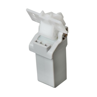
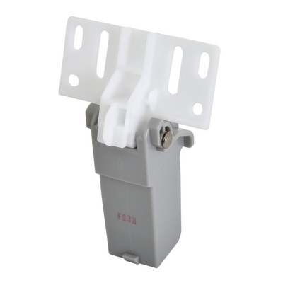
| Деталь: | CONTAINER, WASTE TONER, WT-201 |
| Парткод: | FM0-0015-000 |
| Деталь: | GUIDE, SWING |
| Парткод: | FC0-7048-000 |
| Деталь: | GUIDE, STOPPER, RIGHT DOOR |
| Парткод: | FC0-5942-000 |
| Деталь: | HINGE, EXTERNAL, FRONT |
| Парткод: | FM1-C348-000 |
| Деталь: | LEVER, STOPPER, RIGHT |
| Парткод: | FC0-5912-000 |
| Деталь: | COVER, DOOR CONNECTOR, RIGHT |
| Парткод: | FC0-7708-000 |
| Деталь: | HINGE, OUTER COVER, REAR |
| Парткод: | FC0-5929-000 |
| Деталь: | SCREW,RS,M3X8 |
| Парткод: | XA9-1386-000 |
| Деталь: | BASE, HOOK, RIGHT |
| Парткод: | FC0-5918-000 |
| Деталь: | TRAY, REVERSE |
| Парткод: | FE3-8409-000 |
| Деталь: | INTERNAL COMPONENTS 4 |
| Парткод: | NPN |
| Деталь: | COVER, ADF INNER |
| Парткод: | FC0-5639-000 |
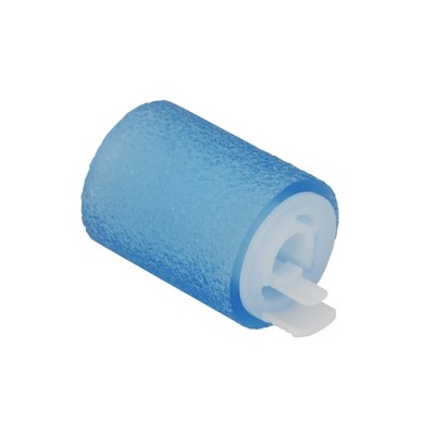
| Деталь: | ROLLER, PICK-UP |
| Парткод: | FC7-6189-000 |
| Цена: | 550 ₽ |
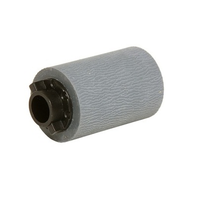
| Деталь: | ROLLER, SEPARATION |
| Парткод: | FL2-6637-000 |
| Цена: | 650 ₽ |
| Деталь: | ADF PAPER PICK-UP ASSEMBLY |
| Парткод: | FM4-9859-000 |
| Цена: | 1 700 ₽ |
| Деталь: | COVER, DF, REAR |
| Парткод: | FL0-2564-000 |
| Деталь: | RING, C,EXTERNAL |
| Парткод: | FE3-7699-000 |
| Деталь: | BUSHING |
| Парткод: | FE3-8298-000 |
| Деталь: | SPRING, COMPRESSION |
| Парткод: | FE3-9145-000 |
| Деталь: | COVER, DF, FRONT |
| Парткод: | FL0-2565-000 |
| Деталь: | GEAR, 23T |
| Парткод: | FE3-8297-000 |
| Деталь: | SPRING, LEAF |
| Парткод: | FE3-8383-000 |
| Деталь: | FEEDER COVER ASSEMBLY |
| Парткод: | FM4-9860-000 |
| Деталь: | COVER, INNER, FRONT, RIGHT |
| Парткод: | FM0-0049-000 |
| Деталь: | COVER, MAIN SWITCH |
| Парткод: | FC0-7172-000 |
| Деталь: | SWITCH |
| Парткод: | WC2-5803-000 |
| Деталь: | SPRING, TENSION |
| Парткод: | FU7-2778-000 |
| Деталь: | LEVER, TOGGLE |
| Парткод: | FE2-2086-000 |
| Деталь: | LABEL, TONER TYPE |
| Парткод: | FC0-7702-000 |
| Деталь: | LABEL, TONER TYPE |
| Парткод: | FC0-7701-000 |
| Деталь: | LABEL, TONER TYPE |
| Парткод: | FC0-7703-000 |
| Деталь: | SCREW,RS,M3X8 |
| Парткод: | XA9-1386-000 |
| Деталь: | REGISTRATION DRIVE ASSY |
| Парткод: | FM1-A225-000 |
| Деталь: | WASTE TONER SENSOR PCB ASSY |
| Парткод: | FM1-C981-000 |
| Деталь: | SPRING, GROUNDING |
| Парткод: | FU2-0577-000 |
| Деталь: | TONER INTER. EJECT ASSY |
| Парткод: | FM0-0037-000 |
| Деталь: | ARM, BOTTLE LOCK |
| Парткод: | FC0-5801-000 |
| Деталь: | CABLE, CONTROL PANEL |
| Парткод: | FK4-0914-000 |
| Деталь: | CABLE, PANEL POWER SUPPLY |
| Парткод: | FM1-A807-000 |
| Деталь: | CONNECTOR, NEW BOTTLE DET., BK |
| Парткод: | FM0-0065-000 |
| Деталь: | CONNECTOR, NEW BOTTLE DET., CL |
| Парткод: | FM0-0075-000 |
| Деталь: | LABEL, PAPER SIZE |
| Парткод: | FE3-8688-000 |
| Деталь: | SHEET, SEPARATION |
| Парткод: | FL3-6526-000 |
| Деталь: | LABEL, MOUNTING INSTRUCTION |
| Парткод: | FE3-9943-000 |
| Деталь: | CONNECTOR, SNAP TIGHT |
| Парткод: | VS1-7440-002 |
| Деталь: | CONNECTOR, SNAP TIGHT, BK |
| Парткод: | VS1-7177-003 |
| Деталь: | PLATE, LIFTING |
| Парткод: | FL0-3261-000 |
| Деталь: | BUSHING |
| Парткод: | FE4-1123-000 |
| Деталь: | PLATE, USB |
| Парткод: | FC0-7486-000 |
| Деталь: | INTERNAL COMPONENTS 1 |
| Парткод: | NPN |
| Деталь: | MOTOR, DC |
| Парткод: | FK4-0638-000 |
| Деталь: | MOTOR, STEPPING |
| Парткод: | FK4-0641-000 |
| Деталь: | FIXING DRIVE ASSEMBLY |
| Парткод: | FM0-0034-000 |
| Деталь: | MOTOR, STEPPING |
| Парткод: | FK4-0640-000 |
| Деталь: | PAPER PICK-UP DRIVE ASSEMBLY |
| Парткод: | FM1-A226-000 |
| Деталь: | COVER, FRONT, UPPER |
| Парткод: | FL3-6519-000 |
| Деталь: | BAND, FRONT COVER, RIGHT |
| Парткод: | FC0-7572-000 |
| Деталь: | PIN, FRONT |
| Парткод: | FC0-7734-000 |
| Деталь: | HOOK, COVER, FRONT |
| Парткод: | FC8-8205-000 |
| Деталь: | ROD, GLASS CLEANING |
| Парткод: | FL0-0237-000 |
| Деталь: | SPRING, COMPRESSION |
| Парткод: | FU9-2007-000 |
| Деталь: | LABEL, CLN ROD OPERATION |
| Парткод: | FC0-5846-000 |
| Деталь: | LABEL, LASER CAUTION |
| Парткод: | FU6-8646-000 |
| Деталь: | LABEL, SERVICE |
| Парткод: | FL3-6534-000 |
| Деталь: | LABEL, SERVICE |
| Парткод: | FL3-6545-000 |
| Деталь: | LABEL, TONER TYPE |
| Парткод: | FC0-7702-000 |
| Деталь: | LABEL, TONER TYPE |
| Парткод: | FC0-7701-000 |
| Деталь: | LABEL, TONER TYPE |
| Парткод: | FC0-7703-000 |
| Деталь: | LABEL,EXCHANGE OPERATOR,BOTTLE |
| Парткод: | FC0-7807-000 |
| Деталь: | DOOR ASSEMBLY, FRONT |
| Парткод: | FM4-9909-000 |
| Деталь: | STOPPER, FREE |
| Парткод: | FC0-7661-000 |
| Деталь: | SHAFT, LIFTER |
| Парткод: | FC0-7662-000 |
| Деталь: | GEAR, 14T |
| Парткод: | FC8-4990-000 |
| Деталь: | GEAR, 68T/37T |
| Парткод: | FE3-1527-000 |
| Деталь: | ROLLER, CASSETTE |
| Парткод: | FE3-1528-000 |
| Деталь: | ARM, SIZE SENSOR LINK |
| Парткод: | FE3-3950-000 |
| Деталь: | SPACER |
| Парткод: | FE3-4476-000 |
| Деталь: | PIN, GUIDE |
| Парткод: | FE3-6143-000 |
| Деталь: | SHEET, SEPARATION |
| Парткод: | FL3-6526-000 |
| Деталь: | PLATE, PAPER SIDE END, FRONT |
| Парткод: | FM1-B545-000 |
| Деталь: | PLATE, BACK END LIMIT |
| Парткод: | FM1-B547-000 |
| Деталь: | PLATE, MIDDLE |
| Парткод: | FM1-B548-000 |
| Деталь: | CASSETTE COVER ASSEMBLY, FRONT |
| Парткод: | FM1-D010-000 |
| Деталь: | GEAR, 14T |
| Парткод: | RC1-9396-000 |
| Деталь: | ARM, GUIDE |
| Парткод: | FC0-7832-000 |
| Деталь: | PIN, ARM |
| Парткод: | FC0-7830-000 |
| Деталь: | SCREW, B, M4X8 |
| Парткод: | XA9-1523-000 |
| Деталь: | PIN, PARALLEL |
| Парткод: | XD9-0290-000 |
| Деталь: | LABEL, CASSETTE |
| Парткод: | FE3-7410-000 |
| Деталь: | BLOCK, PAPER SIDE END |
| Парткод: | FE3-9437-000 |
| Деталь: | PLATE, LINK |
| Парткод: | FE3-6357-000 |
| Деталь: | BLOCK, PAPER SIDE END, REAR |
| Парткод: | FE3-9436-000 |
| Деталь: | BLOCK, PAPER SIDE END, FRONT |
| Парткод: | FE3-9501-000 |
| Деталь: | LABEL, SIZE BACK END OPERATION |
| Парткод: | FE3-9591-000 |
| Деталь: | PIN, PARALLEL |
| Парткод: | XD9-0359-000 |
| Деталь: | RACK, PAPER SIDE END |
| Парткод: | FE4-0306-000 |
| Деталь: | RACK, SIDE |
| Парткод: | FC0-7660-000 |
| Деталь: | PLATE, PAPER SIDE END, REAR |
| Парткод: | FE3-0481-000 |
| Деталь: | HOLDER, DAMPER |
| Парткод: | FE4-1425-000 |
| Деталь: | COVER, DAMPER HOLDER |
| Парткод: | FE4-1426-000 |
| Деталь: | LINK, DAMPER |
| Парткод: | FE4-1427-000 |
| Деталь: | LINK, DAMPER |
| Парткод: | FE4-1428-000 |
| Деталь: | DAMPER, OIL |
| Парткод: | FE4-1500-000 |
| Деталь: | LABEL, ENVELOPE OPERATION |
| Парткод: | FE3-7412-000 |
| Деталь: | WASHER |
| Парткод: | FE3-8153-000 |
| Деталь: | CASSETTE |
| Парткод: | FM0-0019-000 |
| Деталь: | TRAY, MULTI FEED EXTENSION |
| Парткод: | FC0-6621-000 |
| Деталь: | PLATE, PAPER SIDE END, FRONT |
| Парткод: | FC0-7453-000 |
| Деталь: | PLATE, PAPER SIDE END, REAR |
| Парткод: | FC0-7454-000 |
| Деталь: | HOOK, MULTI FEED TRAY |
| Парткод: | FE3-5650-000 |
| Деталь: | SPRING, COMPRESSION |
| Парткод: | FE3-5651-000 |
| Деталь: | CAP, MULTI FEED EXTENSION TRAY |
| Парткод: | FE3-5652-000 |
| Деталь: | SHEET, SEPARATION |
| Парткод: | FL3-6526-000 |
| Деталь: | SPRING, COMPRESSION |
| Парткод: | FU2-0582-000 |
| Деталь: | PINION, SIDE END |
| Парткод: | FU9-0692-000 |
| Деталь: | LABEL, MULTI FEED SIZE |
| Парткод: | FC0-7759-000 |
| Деталь: | LABEL, MULTI FEED SIZE |
| Парткод: | FC0-7761-000 |
| Деталь: | LABEL, MULTI FEED SIZE |
| Парткод: | FC0-7760-000 |
| Деталь: | LABEL, MULTI PICK-UP FULL |
| Парткод: | FE3-3955-000 |
| Деталь: | MULTI FEED TRAY ASSEMBLY |
| Парткод: | FM1-B307-000 |
| Деталь: | MAIN CONTROLLER PCB ASSEMBLY |
| Парткод: | FM1-G964-000 |
| Деталь: | MAIN CONTROLLER PCB ASSEMBLY |
| Парткод: | FM1-G966-000 |
| Деталь: | MAIN CONTROLLER PCB ASSEMBLY |
| Парткод: | FM1-M894-000 |
| Деталь: | SCREW, MACH. PAN HEAD, M3X4 |
| Парткод: | XA9-1979-000 |
| Деталь: | FAN |
| Парткод: | FM1-E996-000 |
| Деталь: | CABLE, SATA POWER |
| Парткод: | FK4-0275-000 |
| Деталь: | CABLE, SATA SIGNAL |
| Парткод: | FK4-0276-000 |
| Деталь: | HARD DISK DRIVE |
| Парткод: | FK4-1550-000 |
| Деталь: | LABEL, CAUTION |
| Парткод: | FU8-8257-000 |
| Деталь: | DAMPER, CUSHION |
| Парткод: | XH9-0149-000 |
| Деталь: | SPACER |
| Парткод: | XZ1-1301-005 |
| Деталь: | COVER, CONTROLLER, SMALL |
| Парткод: | FC0-7477-000 |
| Деталь: | TPM PCB ASSEMBLY |
| Парткод: | FM4-0783-000 |
| Деталь: | IC, R8A03018ABG U100, ASIC |
| Парткод: | FK2-7835-010 |
| Деталь: | IC, T6TH5EFG-0002(0), STANDARD |
| Парткод: | FK2-7852-000 |
| Деталь: | IC, CLOCK GENERATOR, HYBRID |
| Парткод: | FK3-1386-000 |
| Деталь: | IC, AU80610004671AASLBMH, |
| Парткод: | FK3-2212-000 |
| Деталь: | IC, FZC0ZA012AA STANDARD CELL |
| Парткод: | FK3-3034-000 |
| Деталь: | IC, MB87S1801 |
| Парткод: | FK2-8321-000 |
| Деталь: | IC, 88E8075-B0-NNC2C000-W553, |
| Парткод: | FK4-1861-000 |
| Деталь: | CONTROLLER BOX ASSEMBLY |
| Парткод: | NPN |
| Деталь: | ADF MAINTENANCE KIT, DR-201 |
| Парткод: | FM4-9866-000 |
| Деталь: | ADF MAINTENANCE KIT |
| Парткод: | NPN |
| Деталь: | POWER SUPPLY ASSEMBLY |
| Парткод: | FM0-0085-000 |
| Деталь: | POWER SUPPLY ASSEMBLY |
| Парткод: | FM0-0053-000 |
| Деталь: | COVER, READER, REAR, 2 |
| Парткод: | FC0-5614-000 |
| Деталь: | CLAMP, READER SHAFT, RIGHT |
| Парткод: | FE3-8375-000 |
| Деталь: | READER LINK ASSEMBLY |
| Парткод: | FM4-9850-000 |
| Деталь: | HINGE, READER |
| Парткод: | FC0-5544-000 |
| Деталь: | READER/ADF ASSEMBLY |
| Парткод: | NPN |
| Деталь: | ARM, SENSOR |
| Парткод: | FC0-5972-000 |
| Деталь: | BLOCK, WASTE TONER |
| Парткод: | FC0-7589-000 |
| Деталь: | SPRING, COMPRESSION |
| Парткод: | FU2-0574-000 |
| Деталь: | SPRING, TORSION |
| Парткод: | FU9-2027-000 |
| Деталь: | INTERNAL COVER ASSEMBLY |
| Парткод: | NPN |
| Деталь: | CABLE, FAX SIGNAL |
| Парткод: | FM1-D943-000 |
| Деталь: | CABLE, 1 CIRCUIT MODULAR |
| Парткод: | FM1-D944-000 |
| Деталь: | CABLE, HIGH VOLTAGE |
| Парткод: | FM1-D945-000 |
| Деталь: | CABLE, 1 CIRCUIT SPEAKER |
| Парткод: | FM1-D946-000 |
| Деталь: | CONNECTOR, SNAP TIGHT, BK |
| Парткод: | VS1-7177-002 |
| Деталь: | OFF-HOOK DETECT PCB ASSEMBLY |
| Парткод: | FM3-2163-000 |
| Деталь: | MODULAR PCB ASSY, 1 CIRCUIT |
| Парткод: | FM4-0834-000 |
| Деталь: | MODULAR PCB ASSY, 1 CIRCUIT |
| Парткод: | FM4-0835-000 |
| Деталь: | MODULAR PCB ASSY, 1 CIRCUIT |
| Парткод: | FM1-G905-000 |
| Деталь: | 1 LINE PCB ASSEMBLY |
| Парткод: | FM4-0838-010 |
| Деталь: | 1 LINE PCB ASSEMBLY |
| Парткод: | FM4-0856-010 |
| Деталь: | SPACER,MODULAR |
| Парткод: | WT8-5076-000 |
| Деталь: | FAX ASSEMBLY |
| Парткод: | NPN |
| Деталь: | 1ST TRANSFER H.V. PCB ASSEMBLY |
| Парткод: | FM0-0050-000 |
| Деталь: | CABLE, FLAT |
| Парткод: | FK4-0647-000 |
| Деталь: | CABLE, REG. MOTOR WASTE TONER |
| Парткод: | FM1-A836-000 |
| Деталь: | CABLE, CASSETTE HEATER |
| Парткод: | FM1-A811-000 |
| Деталь: | CABLE, CASSETTE HEATER |
| Парткод: | FM1-A812-000 |
| Деталь: | HEATER, CASSETTE |
| Парткод: | FM1-B513-000 |
| Деталь: | CAP, CONNECTOR |
| Парткод: | FE3-4477-000 |
| Деталь: | PANEL, CST. HEATER CONNECTOR |
| Парткод: | FE3-4478-000 |
| Деталь: | FOOT, RUBBER |
| Парткод: | FM1-B574-000 |
| Деталь: | CASSETTE STOPPER ASSEMBLY |
| Парткод: | FM1-B298-000 |
| Деталь: | OPTION CST. DRAWER ASSEMBLY |
| Парткод: | FM1-C323-000 |
| Деталь: | SCREW,RS,M3X8 |
| Парткод: | XA9-1386-000 |
| Деталь: | INTERNAL COMPONENTS 5 |
| Парткод: | NPN |
| Деталь: | BUSHING |
| Парткод: | FC0-5876-000 |
| Деталь: | GUIDE, DUPLEXING |
| Парткод: | FC0-5886-000 |
| Деталь: | BUSHING |
| Парткод: | FC0-5888-000 |
| Деталь: | ROLLER, DUPLEXING FEED |
| Парткод: | FL3-6443-000 |
| Деталь: | PLANETARY ONE-WAY GEAR ASSY |
| Парткод: | FM1-B551-000 |
| Деталь: | GEAR, 25T |
| Парткод: | FU9-0663-000 |
| Деталь: | GEAR, 23T |
| Парткод: | FU9-0666-000 |
| Деталь: | GEAR, 25T/14T |
| Парткод: | FU9-0672-000 |
| Деталь: | GEAR, 16T |
| Парткод: | FU9-0720-000 |
| Деталь: | DUPLEXING GUIDE ASSEMBLY |
| Парткод: | NPN |
Коды ошибок
E001-A001
E001-A002
E001-A003
E001-A004
E001-A005
E001-A006
E002-A001
E002-A002
E002-A003
E002-A004
E003-A001
E003-A002
E003-A003
E004-0001
E004-0002
E009-0001
E009-0002
E009-0003
E009-0004
E010-0001
E010-0002
E010-0003
E012-0001
E012-0002
E012-0003
E014-0001
E014-0002
E014-0003
E020-01A8
E020-01B8
E020-01C0
E020-01F0
E020-02A8
E020-02B8
E020-02C0
E020-02F0
E020-03A8
E020-03B8
E020-03C0
E020-03F0
E020-04A8
E020-04B8
E020-04C0
E020-04F0
E021-0001
E021-0002
E021-0003
E021-0120
E021-0220
E021-0320
E021-0420
E025-0110
E025-0168
E025-0210
E025-0268
E025-0310
E025-0368
E025-0410
E025-0468
E029-5008
E029-7008
E073-0001
E074-0000
E074-0002
E100-0001
E102-0001
E110-0001
E110-0002
E110-0003
E193-0001
E196-0000
E196-0001
E196-0002
E196-0003
E196-000F
E196-0100
E196-0101
E196-0102
E196-010F
E196-0200
E196-0201
E196-0202
E196-020F
E196-0300
E196-0301
E196-0302
E196-030F
E196-0400
E196-0401
E196-0402
E196-040F
E196-0500
E196-0501
E196-0502
E196-050F
E196-0600
E196-0601
E196-0602
E196-060F
E196-0800
E196-0801
E196-0802
E196-080F
E197-0000
E197-0F00
E197-1000
E197-1F00
E197-2000
E197-2101
E197-2F00
E202-0001
E202-0002
E240-0000
E240-0005
E240-0D00
E246
E247
E248-0001
E248-0002
E280-0004
E280-0005
E301-0001
E301-0002
E315-0007
E315-000D
E315-000E
E315-000F
E315-0027
E315-0035
E315-0100
E315-0500
E315-0501
E315-0510
E315-0511
E315-0520
E315-0521
E315-0530
E315-0531
E315-0540
E315-0541
E315-0550
E315-0551
E350
E351-0000
E354
E355
E500-0000
E530-0001
E530-0002
E531-8001
E531-8002
E537-0001
E537-0002
E540-0001
E575-0001
E575-0002
E575-0004
E577-0001
E577-0002
E583-0001
E583-0002
E602
E611-0000
E614
E615-0001
E674-0001
E674-0004
E674-0008
E674-000C
E674-0010
E674-0011
E674-0100
E674-0200
E713-0000
E719-0001
E719-0002
E719-0003
E719-0031
E719-0032
E720-0000
E720-0100
E730-A006
E730-A007
E730-B013
E732-0001
E732-0010
E733-0000
E733-0001
E733-0002
E733-0F00
E733-0F01
E733-0F02
E733-F001
E733-F002
E743-0000
E744-0001
E744-4000
E746-0022
E746-0023
E746-0024
E746-0031
E746-0032
E746-0033
E746-0034
E746-0035
E748-2010
E748-9000
E749-0005
E749-0006
E753-0001
E804-0000
E806-0100
E806-0101
E806-0300
E806-0301
E806-0400
E806-0401
E808-0001
E880-0001
E881-0001
E996-0071
E996-0CA0
E996-0CA1
E996-0CA2
E996-0CA3
E996-0CA4
E996-0CA9
E996-0CAB
E996-0CAD
E996-0CAE
E996-0CAF
Описание
| Error code: | E001-A001 |
| Description: | Fixing Main Thermistor high temperature detection error The Fixing Main Thermistor detected 265 deg C or higher for 0.1 sec or longer. |
| Remedy: | [Related parts] - Fixing Assembly (Unit of replacement: Fixing Assembly) - Low-voltage Power Supply PCB (UN01) (Unit of replacement: POWER SUPPLY ASSEMBLY) - DC Controller PCB (UN04) (Unit of replacement: DC CONTROLLER PCB ASSEMBLY) - Harness between the Fixing Drawer (DR01/J5401) and the Low-voltage Power Supply PCB (UN01/J302) (Unit of replacement: INTERLOCK ASSEMBLY) - Harness between the Low-voltage Power Supply PCB (UN01/ J315 and J322) and the DC Controller PCB (UN04/J20 and J22) (Unit of replacement: CABLE, POWER SUPPLY) - Harness between the Fixing Drawer (DR01/J5401) and the DC Controller PCB (UN04/J134) (Unit of replacement: INTERLOCK ASSEMBLY) [Points to note at work] When checking the harness/cable or connector, perform the following work. 1. Disconnect and then connect the connector to check that there is no bent pin and cable disconnection. 2. Visually check that the harness is not caught or open circuit. 3. If there is any error, replace the corresponding harness/cable. [Remedy] Check/replace the related parts. [Reference] Before replacing the DC Controller PCB, back up the service mode data (approx. 2 min) and restore the backup data after the replacement so the data may be able to be protected. - Backup: COPIER (LEVEL2)> FUNCTION> SYSTEM> DSRAMBUP - Restoration: COPIER (LEVEL2)> FUNCTION> SYSTEM> DSRAMRES |
| Error code: | E001-A002 |
| Description: | Fixing Sub Thermistor (Front) high temperature detection error The Fixing Sub Thermistor (Front) detected 290 deg C or higher for 0.1 sec or longer. |
| Remedy: | [Related parts] - Fixing Assembly (Unit of replacement: Fixing Assembly) - Low-voltage Power Supply PCB (UN01) (Unit of replacement: POWER SUPPLY ASSEMBLY) - DC Controller PCB (UN04) (Unit of replacement: DC CONTROLLER PCB ASSEMBLY) - Harness between the Fixing Drawer (DR01/J5401) and the Low-voltage Power Supply PCB (UN01/J302) (Unit of replacement: INTERLOCK ASSEMBLY) - Harness between the Low-voltage Power Supply PCB (UN01/ J315 and J322) and the DC Controller PCB (UN04/J20 and J22) (Unit of replacement: CABLE, POWER SUPPLY) - Harness between the Fixing Drawer (DR01/J5401) and the DC Controller PCB (UN04/J134) (Unit of replacement: INTERLOCK ASSEMBLY) [Points to note at work] When checking the harness/cable or connector, perform the following work. 1. Disconnect and then connect the connector to check that there is no bent pin and cable disconnection. 2. Visually check that the harness is not caught or open circuit. 3. If there is any error, replace the corresponding harness/cable. [Remedy] Check/replace the related parts. [Reference] Before replacing the DC Controller PCB, back up the service mode data (approx. 2 min) and restore the backup data after the replacement so the data may be able to be protected. - Backup: COPIER (LEVEL2)> FUNCTION> SYSTEM> DSRAMBUP - Restoration: COPIER (LEVEL2)> FUNCTION> SYSTEM> DSRAMRES |
| Error code: | E001-A003 |
| Description: | Fixing Sub Thermistor (Rear) high temperature detection error The Fixing Sub Thermistor (Rear) detected 290 deg C or higher for 0.1 sec or longer. |
| Remedy: | [Related parts] - Fixing Assembly (Unit of replacement: Fixing Assembly) - Low-voltage Power Supply PCB (UN01) (Unit of replacement: POWER SUPPLY ASSEMBLY) - DC Controller PCB (UN04) (Unit of replacement: DC CONTROLLER PCB ASSEMBLY) - Harness between the Fixing Drawer (DR01/J5401) and the Low-voltage Power Supply PCB (UN01/J302) (Unit of replacement: INTERLOCK ASSEMBLY) - Harness between the Low-voltage Power Supply PCB (UN01/ J315 and J322) and the DC Controller PCB (UN04/J20 and J22) (Unit of replacement: CABLE, POWER SUPPLY) - Harness between the Fixing Drawer (DR01/J5401) and the DC Controller PCB (UN04/J134) (Unit of replacement: INTERLOCK ASSEMBLY) [Points to note at work] When checking the harness/cable or connector, perform the following work. 1. Disconnect and then connect the connector to check that there is no bent pin and cable disconnection. 2. Visually check that the harness is not caught or open circuit. 3. If there is any error, replace the corresponding harness/cable. [Remedy] Check/replace the related parts. [Reference] Before replacing the DC Controller PCB, back up the service mode data (approx. 2 min) and restore the backup data after the replacement so the data may be able to be protected. - Backup: COPIER (LEVEL2)> FUNCTION> SYSTEM> DSRAMBUP - Restoration: COPIER (LEVEL2)> FUNCTION> SYSTEM> DSRAMRES |
| Error code: | E001-A004 |
| Description: | Fixing Main Thermistor high temperature detection error The Fixing Main Thermistor detected 270 deg C or higher |
| Remedy: | [Related parts] - Fixing Assembly (Unit of replacement: Fixing Assembly) - Low-voltage Power Supply PCB (UN01) (Unit of replacement: POWER SUPPLY ASSEMBLY) - DC Controller PCB (UN04) (Unit of replacement: DC CONTROLLER PCB ASSEMBLY) - Harness between the Fixing Drawer (DR01/J5401) and the Low-voltage Power Supply PCB (UN01/J302) (Unit of replacement: INTERLOCK ASSEMBLY) - Harness between the Low-voltage Power Supply PCB (UN01/ J315 and J322) and the DC Controller PCB (UN04/J20 and J22) (Unit of replacement: CABLE, POWER SUPPLY) - Harness between the Fixing Drawer (DR01/J5401) and the DC Controller PCB (UN04/J134) (Unit of replacement: INTERLOCK ASSEMBLY) [Points to note at work] When checking the harness/cable or connector, perform the following work. 1. Disconnect and then connect the connector to check that there is no bent pin and cable disconnection. 2. Visually check that the harness is not caught or open circuit. 3. If there is any error, replace the corresponding harness/cable. [Remedy] Check/replace the related parts. [Reference] Before replacing the DC Controller PCB, back up the service mode data (approx. 2 min) and restore the backup data after the replacement so the data may be able to be protected. - Backup: COPIER (LEVEL2)> FUNCTION> SYSTEM> DSRAMBUP - Restoration: COPIER (LEVEL2)> FUNCTION> SYSTEM> DSRAMRES |
| Error code: | E001-A005 |
| Description: | Fixing Sub Thermistor (Front) high temperature detection error The Fixing Sub Thermistor (Front) detected 295 deg C or higher. |
| Remedy: | [Related parts] - Fixing Assembly (Unit of replacement: Fixing Assembly) - Low-voltage Power Supply PCB (UN01) (Unit of replacement: POWER SUPPLY ASSEMBLY) - DC Controller PCB (UN04) (Unit of replacement: DC CONTROLLER PCB ASSEMBLY) - Harness between the Fixing Drawer (DR01/J5401) and the Low-voltage Power Supply PCB (UN01/J302) (Unit of replacement: INTERLOCK ASSEMBLY) - Harness between the Low-voltage Power Supply PCB (UN01/ J315 and J322) and the DC Controller PCB (UN04/J20 and J22) (Unit of replacement: CABLE, POWER SUPPLY) - Harness between the Fixing Drawer (DR01/J5401) and the DC Controller PCB (UN04/J134) (Unit of replacement: INTERLOCK ASSEMBLY) [Points to note at work] When checking the harness/cable or connector, perform the following work. 1. Disconnect and then connect the connector to check that there is no bent pin and cable disconnection. 2. Visually check that the harness is not caught or open circuit. 3. If there is any error, replace the corresponding harness/cable. [Remedy] Check/replace the related parts. [Reference] Before replacing the DC Controller PCB, back up the service mode data (approx. 2 min) and restore the backup data after the replacement so the data may be able to be protected. - Backup: COPIER (LEVEL2)> FUNCTION> SYSTEM> DSRAMBUP - Restoration: COPIER (LEVEL2)> FUNCTION> SYSTEM> DSRAMRES |
| Error code: | E001-A006 |
| Description: | Fixing Sub Thermistor (Rear) high temperature detection error The Fixing Sub Thermistor (Rear) detected 295 deg C or higher. |
| Remedy: | [Related parts] - Fixing Assembly (Unit of replacement: Fixing Assembly) - Low-voltage Power Supply PCB (UN01) (Unit of replacement: POWER SUPPLY ASSEMBLY) - DC Controller PCB (UN04) (Unit of replacement: DC CONTROLLER PCB ASSEMBLY) - Harness between the Fixing Drawer (DR01/J5401) and the Low-voltage Power Supply PCB (UN01/J302) (Unit of replacement: INTERLOCK ASSEMBLY) - Harness between the Low-voltage Power Supply PCB (UN01/ J315 and J322) and the DC Controller PCB (UN04/J20 and J22) (Unit of replacement: CABLE, POWER SUPPLY) - Harness between the Fixing Drawer (DR01/J5401) and the DC Controller PCB (UN04/J134) (Unit of replacement: INTERLOCK ASSEMBLY) [Points to note at work] When checking the harness/cable or connector, perform the following work. 1. Disconnect and then connect the connector to check that there is no bent pin and cable disconnection. 2. Visually check that the harness is not caught or open circuit. 3. If there is any error, replace the corresponding harness/cable. [Remedy] Check/replace the related parts. [Reference] Before replacing the DC Controller PCB, back up the service mode data (approx. 2 min) and restore the backup data after the replacement so the data may be able to be protected. - Backup: COPIER (LEVEL2)> FUNCTION> SYSTEM> DSRAMBUP - Restoration: COPIER (LEVEL2)> FUNCTION> SYSTEM> DSRAMRES |
| Error code: | E002-A001 |
| Description: | Fixing Main Thermistor temperature increase detection error The Fixing Main Thermistor detected a temperature increase of 1 deg C for less than 5 sec from turning ON the main power until start of PI control. |
| Remedy: | [Related parts] - Low-voltage Power Supply PCB (UN01) (Unit of replacement: POWER SUPPLY ASSEMBLY) - Fixing Assembly (Unit of replacement: Fixing Assembly) - DC Controller PCB (UN04) (Unit of replacement: DC CONTROLLER PCB ASSEMBLY) - Harness between the Fixing Drawer (DR01/J5401) and the Low-voltage Power Supply PCB (UN01/J302) (Unit of replacement: INTERLOCK ASSEMBLY) - Harness between the Low-voltage Power Supply PCB (UN01/ J315 and J322) and the DC Controller PCB (UN04/J20 and J22) (Unit of replacement: CABLE, POWER SUPPLY) - Harness between the Fixing Drawer (DR01/J5401) and the DC Controller PCB (UN04/J134) (Unit of replacement: INTERLOCK ASSEMBLY) [Points to note at work] When checking the harness/cable or connector, perform the following work. 1. Disconnect and then connect the connector to check that there is no bent pin and cable disconnection. 2. Visually check that the harness is not caught or open circuit. 3. If there is any error, replace the corresponding harness/cable. [Remedy] Check/replace the related parts. [Reference] Before replacing the DC Controller PCB, back up the service mode data (approx. 2 min) and restore the backup data after the replacement so the data may be able to be protected. - Backup: COPIER (LEVEL2)> FUNCTION> SYSTEM> DSRAMBUP - Restoration: COPIER (LEVEL2)> FUNCTION> SYSTEM> DSRAMRES |
| Error code: | E002-A002 |
| Description: | Fixing Main Thermistor open circuit detection error The Fixing Main Thermistor detected a temperature of 40 deg C or lower for 3 sec or longer from turning ON the main power until start of PI control. |
| Remedy: | [Related parts] - Low-voltage Power Supply PCB (UN01) (Unit of replacement: POWER SUPPLY ASSEMBLY) - Fixing Assembly (Unit of replacement: Fixing Assembly) - DC Controller PCB (UN04) (Unit of replacement: DC CONTROLLER PCB ASSEMBLY) - Harness between the Fixing Drawer (DR01/J5401) and the Low-voltage Power Supply PCB (UN01/J302) (Unit of replacement: INTERLOCK ASSEMBLY) - Harness between the Low-voltage Power Supply PCB (UN01/ J315 and J322) and the DC Controller PCB (UN04/J20 and J22) (Unit of replacement: CABLE, POWER SUPPLY) - Harness between the Fixing Drawer (DR01/J5401) and the DC Controller PCB (UN04/J134) (Unit of replacement: INTERLOCK ASSEMBLY) [Points to note at work] When checking the harness/cable or connector, perform the following work. 1. Disconnect and then connect the connector to check that there is no bent pin and cable disconnection. 2. Visually check that the harness is not caught or open circuit. 3. If there is any error, replace the corresponding harness/cable. [Remedy] Check/replace the related parts. [Reference] Before replacing the DC Controller PCB, back up the service mode data (approx. 2 min) and restore the backup data after the replacement so the data may be able to be protected. - Backup: COPIER (LEVEL2)> FUNCTION> SYSTEM> DSRAMBUP - Restoration: COPIER (LEVEL2)> FUNCTION> SYSTEM> DSRAMRES |
| Error code: | E002-A003 |
| Description: | Fixing Sub Thermistor (Front) open circuit detection error The Fixing Sub Thermistor (Front) detected a temperature of 40 deg C or lower for 3 sec or longer from turning ON the main power until start of PI control. |
| Remedy: | [Related parts] - Low-voltage Power Supply PCB (UN01) (Unit of replacement: POWER SUPPLY ASSEMBLY) - Fixing Assembly (Unit of replacement: Fixing Assembly) - DC Controller PCB (UN04) (Unit of replacement: DC CONTROLLER PCB ASSEMBLY) - Harness between the Fixing Drawer (DR01/J5401) and the Low-voltage Power Supply PCB (UN01/J302) (Unit of replacement: INTERLOCK ASSEMBLY) - Harness between the Low-voltage Power Supply PCB (UN01/ J315 and J322) and the DC Controller PCB (UN04/J20 and J22) (Unit of replacement: CABLE, POWER SUPPLY) - Harness between the Fixing Drawer (DR01/J5401) and the DC Controller PCB (UN04/J134) (Unit of replacement: INTERLOCK ASSEMBLY) [Points to note at work] When checking the harness/cable or connector, perform the following work. 1. Disconnect and then connect the connector to check that there is no bent pin and cable disconnection. 2. Visually check that the harness is not caught or open circuit. 3. If there is any error, replace the corresponding harness/cable. [Remedy] Check/replace the related parts. [Reference] Before replacing the DC Controller PCB, back up the service mode data (approx. 2 min) and restore the backup data after the replacement so the data may be able to be protected. - Backup: COPIER (LEVEL2)> FUNCTION> SYSTEM> DSRAMBUP - Restoration: COPIER (LEVEL2)> FUNCTION> SYSTEM> DSRAMRES |
| Error code: | E002-A004 |
| Description: | Fixing Sub Thermistor (Rear) open circuit detection error The Fixing Sub Thermistor (Rear) detected a temperature of 40 deg C or lower for 3 sec or longer from turning ON the main power until start of PI control. |
| Remedy: | [Related parts] - Low-voltage Power Supply PCB (UN01) (Unit of replacement: POWER SUPPLY ASSEMBLY) - Fixing Assembly (Unit of replacement: Fixing Assembly) - DC Controller PCB (UN04) (Unit of replacement: DC CONTROLLER PCB ASSEMBLY) - Harness between the Fixing Drawer (DR01/J5401) and the Low-voltage Power Supply PCB (UN01/J302) (Unit of replacement: INTERLOCK ASSEMBLY) - Harness between the Low-voltage Power Supply PCB (UN01/ J315 and J322) and the DC Controller PCB (UN04/J20 and J22) (Unit of replacement: CABLE, POWER SUPPLY) - Harness between the Fixing Drawer (DR01/J5401) and the DC Controller PCB (UN04/J134) (Unit of replacement: INTERLOCK ASSEMBLY) [Points to note at work] When checking the harness/cable or connector, perform the following work. 1. Disconnect and then connect the connector to check that there is no bent pin and cable disconnection. 2. Visually check that the harness is not caught or open circuit. 3. If there is any error, replace the corresponding harness/cable. [Remedy] Check/replace the related parts. [Reference] Before replacing the DC Controller PCB, back up the service mode data (approx. 2 min) and restore the backup data after the replacement so the data may be able to be protected. - Backup: COPIER (LEVEL2)> FUNCTION> SYSTEM> DSRAMBUP - Restoration: COPIER (LEVEL2)> FUNCTION> SYSTEM> DSRAMRES |
| Error code: | E003-A001 |
| Description: | Fixing Main Thermistor low temperature detection error (during printing) The Fixing Main Thermistor detected a temperature of 80 deg C or lower for 1 sec or longer from start of PI control until completion of the last rotation (the Fixing Heater is turned OFF) during printing. |
| Remedy: | [Related parts] - Fixing Assembly (Unit of replacement: Fixing Assembly) - Low-voltage Power Supply PCB (UN01) (Unit of replacement: POWER SUPPLY ASSEMBLY) - DC Controller PCB (UN04) (Unit of replacement: DC CONTROLLER PCB ASSEMBLY) - Harness between the Fixing Drawer (DR01/J5401) and the Low-voltage Power Supply PCB (UN01/J302) (Unit of replacement: INTERLOCK ASSEMBLY) - Harness between the Low-voltage Power Supply PCB (UN01/ J315 and J322) and the DC Controller PCB (UN04/J20 and J22) (Unit of replacement: CABLE, POWER SUPPLY) - Harness between the Fixing Drawer (DR01/J5401) and the DC Controller PCB (UN04/J134) (Unit of replacement: INTERLOCK ASSEMBLY) [Points to note at work] When checking the harness/cable or connector, perform the following work. 1. Disconnect and then connect the connector to check that there is no bent pin and cable disconnection. 2. Visually check that the harness is not caught or open circuit. 3. If there is any error, replace the corresponding harness/cable. [Remedy] Check/replace the related parts. [Reference] Before replacing the DC Controller PCB, back up the service mode data (approx. 2 min) and restore the backup data after the replacement so the data may be able to be protected. - Backup: COPIER (LEVEL2)> FUNCTION> SYSTEM> DSRAMBUP - Restoration: COPIER (LEVEL2)> FUNCTION> SYSTEM> DSRAMRES |
| Error code: | E003-A002 |
| Description: | Fixing Sub Thermistor (Front) low temperature detection error The Fixing Sub Thermistor (Front) detected a temperature of 80 deg C or lower for 1 sec or longer from start of PI control until completion of the last rotation (the Fixing Heater is turned OFF) during printing. |
| Remedy: | [Related parts] - Fixing Assembly (Unit of replacement: Fixing Assembly) - Low-voltage Power Supply PCB (UN01) (Unit of replacement: POWER SUPPLY ASSEMBLY) - DC Controller PCB (UN04) (Unit of replacement: DC CONTROLLER PCB ASSEMBLY) - Harness between the Fixing Drawer (DR01/J5401) and the Low-voltage Power Supply PCB (UN01/J302) (Unit of replacement: INTERLOCK ASSEMBLY) - Harness between the Low-voltage Power Supply PCB (UN01/ J315 and J322) and the DC Controller PCB (UN04/J20 and J22) (Unit of replacement: CABLE, POWER SUPPLY) - Harness between the Fixing Drawer (DR01/J5401) and the DC Controller PCB (UN04/J134) (Unit of replacement: INTERLOCK ASSEMBLY) [Points to note at work] When checking the harness/cable or connector, perform the following work. 1. Disconnect and then connect the connector to check that there is no bent pin and cable disconnection. 2. Visually check that the harness is not caught or open circuit. 3. If there is any error, replace the corresponding harness/cable. [Remedy] Check/replace the related parts. [Reference] Before replacing the DC Controller PCB, back up the service mode data (approx. 2 min) and restore the backup data after the replacement so the data may be able to be protected. - Backup: COPIER (LEVEL2)> FUNCTION> SYSTEM> DSRAMBUP - Restoration: COPIER (LEVEL2)> FUNCTION> SYSTEM> DSRAMRESs |
| Error code: | E003-A003 |
| Description: | Fixing Sub Thermistor (Rear) low temperature detection error The Fixing Sub Thermistor (Rear) detected a temperature of 80 deg C or lower for 1 sec or longer from start of PI control until completion of the last rotation (the Fixing Heater is turned OFF) during printing. |
| Remedy: | [Related parts] - Fixing Assembly (Unit of replacement: Fixing Assembly) - Low-voltage Power Supply PCB (UN01) (Unit of replacement: POWER SUPPLY ASSEMBLY) - DC Controller PCB (UN04) (Unit of replacement: DC CONTROLLER PCB ASSEMBLY) - Harness between the Fixing Drawer (DR01/J5401) and the Low-voltage Power Supply PCB (UN01/J302) (Unit of replacement: INTERLOCK ASSEMBLY) - Harness between the Low-voltage Power Supply PCB (UN01/ J315 and J322) and the DC Controller PCB (UN04/J20 and J22) (Unit of replacement: CABLE, POWER SUPPLY) - Harness between the Fixing Drawer (DR01/J5401) and the DC Controller PCB (UN04/J134) (Unit of replacement: INTERLOCK ASSEMBLY) [Points to note at work] When checking the harness/cable or connector, perform the following work. 1. Disconnect and then connect the connector to check that there is no bent pin and cable disconnection. 2. Visually check that the harness is not caught or open circuit. 3. If there is any error, replace the corresponding harness/cable. [Remedy] Check/replace the related parts. [Reference] Before replacing the DC Controller PCB, back up the service mode data (approx. 2 min) and restore the backup data after the replacement so the data may be able to be protected. - Backup: COPIER (LEVEL2)> FUNCTION> SYSTEM> DSRAMBUP - Restoration: COPIER (LEVEL2)> FUNCTION> SYSTEM> DSRAMRES |
| Error code: | E004-0001 |
| Description: | There is an error in the fixing assembly protection circuit. There is an open circuit or poor contact in the main thermistor (THM1, THM2, THM3) or sub thermistor (TH4, THM5, THM6). The AC driver PCB or the DC controller PCB has a fault. There is an SSR error in the outside heating roller heater. |
| Remedy: | Check the main thermistor and the sub thermistor for an open circuit and poor contact; then, reset in service mode: COPIER>FUNCTION>CLEAR>ERR. |
| Error code: | E004-0002 |
| Description: | There is an error in the fixing assembly protection circuit. There is an open circuit or poor contact in the main thermistor (THM1, THM2, THM3) or sub thermistor (TH4, THM5, THM6). The AC driver PCB or the DC controller PCB has a fault. There is an SSR error in the fixing sub heater. |
| Remedy: | Check the main thermistor and the sub thermistor for an open circuit and poor contact; then, reset in service mode: COPIER>FUNCTION>CLEAR>ERR. |
| Error code: | E009-0001 |
| Description: | Error in pressure/release of fixing film unit In case that the output of fixing automatic pressure phase sensor is not changed although rotating/reversing the fixing motor |
| Remedy: | Check the pressure/release mechanism. Check the connection of the connector. Replace the motor. |
| Error code: | E009-0002 |
| Description: | Pressure error (it is highly possible that grease is scattered on the surface of the cam.) Unable to detect stopping of the cam at the specified position even if pressure is applied 10 times. |
| Remedy: | Clean the scattered grease and excess grease on the gear at the rear side of the host machine. Procedure is as follows. 1. Remove the Fixing Assembly. 2. Remove the Gear Cover at the rear side of the host machine, and remove the Pressure Release Stopper and the Pressure Release Support Plate (so that the gear is easily cleaned). 3. Wipe off the scattered grease around the Pressure Release Cam and the Pressure Plate with lint-free paper moistened with alcohol. 4. Wipe off the excess grease on the side of the gear and the shaft. |
| Error code: | E009-0003 |
| Description: | Fixing pressure retry error Signal of the Fixing Pressure Release Sensor could not be detected at pressure application operation of the Fixing Pressure Release Cam, and the operation was not completed within 3 times from the start of counterclockwise rotation of the Fixing Motor. |
| Remedy: | [Remedy] Replace the Fixing Assembly. (Unit of replacement: Fixing Assembly) |
| Error code: | E009-0004 |
| Description: | Fixing disengagement retry error Signal of the Fixing Pressure Release Sensor could not be detected at pressure release operation of the Fixing Pressure Release Cam, and the operation was not completed within 3 times from the start of counterclockwise rotation of the Fixing Motor. |
| Remedy: | Replace the Fixing Assembly. (Unit of replacement: Fixing Assembly) |
| Error code: | E010-0001 |
| Description: | Main motor error Lock of the motor fails to be detected 2 sec or more after the motor starts to operate. |
| Causes: | The main motor drive system has an excess load. The pickup main motor (M2)/delivery main motor (M16)/pedestal main motor (M19) is faulty. The serial driver PCB is faulty. The DC controller PCB is faulty. |
| Remedy: | Check on connection of the connector, Replace the motor |
| Error code: | E010-0002 |
| Description: | Main motor error After rotation of the motor becomes stable, the motor lock fails (i.e., the motor becomes unstable) for 500msec or more. |
| Causes: | The main motor drive system has an excess load. The pickup main motor (M2)/delivery main motor (M16)/pedestal main motor (M19) is faulty. The serial driver PCB is faulty. The DC controller PCB is faulty. |
| Remedy: | Check on connection of the connector, Replace the motor |
| Error code: | E010-0003 |
| Description: | The pedestal main motor (M19) is released. The motor is checked every 10 msec from 2000 msec after it is started to when it is stopped. However, detection is not made when the front cover/delivery assembly cover/face-down delivery unit is released or when there is a fault in the power supply system. |
| Causes: | The main motor drive system has an excess load. The pickup main motor (M2)/delivery main motor (M16)/pedestal main motor (M19) is faulty. The serial driver PCB is faulty. The DC controller PCB is faulty. |
| Remedy: | Possible cause is overload or rotation failure of the motor due to an electrical trouble 1. Check the Main Drive Unit (turn the unit by hand to see if it rotates) Replace the Main Drive Unit when the unit failed to rotate When the unit rotates 2. Check failure of the harness between the ITB Motor (M02/ J6027) and the DC Controller PCB (UN09/ J210W) (trapped cable, open circuit, connector disconnection) 3. Check conduction of the fuse (FU4) in the DC Controller PCB (UN09) When the fuse is not blown out 4-1. Replace the ITB Motor (M02) 5-1. Replace the DC Controller PCB (UN09) 6-1. Replace the Main Drive Unit When the fuse is blown out 4-2. Replace the DC Controller PCB (UN09) |
| Error code: | E012-0001 |
| Description: | Error in ITB motor activation. |
| Causes: | If the ITB motor speed detection signal comes off the specified cycle after it turned once to the specified cycle. Cause Failure in ITB motor, failure in DC controller PCB. |
| Remedy: | - Check the connectors of ITB motor and DC controller PCB - Replace the ITB motor - Replace the DC controller PCB |
| Error code: | E012-0002 |
| Description: | ITB motor or drum motor failure |
| Causes: | Yellow drum motor error (Failure in drum motor initial operation) The target speed was not reached within a specified time after startup of the motor |
| Remedy: | Check the contact of the connector between the drum motor (J515) and the DC controller PCB (J81). Replace the drum motor. Replace the main drive assembly. |
| Error code: | E012-0003 |
| Description: | ITB motor or drum motor failure |
| Causes: | Yellow drum motor error (Failure in drum motor rotation) The motor rotated out of the target speed during rotation after the target speed was reached. |
| Remedy: | Check the contact of the connector between the drum motor (J515) and the DC controller PCB (J81). Replace the drum motor. Replace the main drive assembly |
| Error code: | E014-0001 |
| Description: | Fixing motor failure |
| Causes: | Fixing motor rotation error The motor rotated out of the target speed during rotation after the target speed was reached. |
| Remedy: | Check the contact of the connector between the fixing motor (J516) and the DC controller PCB (J81). Check the gear between the fixing motor and the fixing assembly. Replace the fixing motor. |
| Error code: | E014-0002 |
| Description: | Fixing motor error When the lock was disengaged after the motor was locked |
| Causes: | The belt motor (M15) is faulty. The belt motor drive system has an excess load. The drum drive AC generation PCB is faulty. The transfer drive AC generation PCB is faulty. The DC controller PCB is faulty. |
| Remedy: | Replace the drumITB moter. Replace the fixing moter.Replace the DCDC converterAi38VAj. Replace the fixing belt unit. |
| Error code: | E014-0003 |
| Description: | The encoder signal is not generated by the motor. |
| Causes: | The belt motor (M15) is faulty. The belt motor drive system has an excess load. The drum drive AC generation PCB is faulty. The transfer drive AC generation PCB is faulty. The DC controller PCB is faulty. |
| Remedy: | Possible cause is overload or rotation failure of the motor due to an electrical trouble 1. Check if the Fixing Assembly is installed. 2. Remove and reinstall the Fixing Assembly 3. Check the gear 4. Replace the Fixing Assembly 5. Check the harness/connector between the DC Controller PCB (UN09/ J210) and the Fixing Motor (M17). 6. Check conduction of FU1153 in the AC Driver PCB (UN14) =>Replace the AC Driver when the fuse is blown out 7. Replace the Fixing Motor (M17) 8. Replace the DC Controller PCB (UN09) |
| Error code: | E020-01A8 |
| Description: | ATR Sensor (Y)output error The output value of the ATR Sensor (Y) in the Drum Unit (Y) did not fall within the range from 10 or higher to 245 or less for 2 consecutive times during printing. |
| Remedy: | [Related parts] - ATR Sensor (Y) (UN34) (Unit of replacement: DEVE_UNIT_Y) - Drum Unit (Y) (Unit of replacement: DEVE_UNIT_Y) - Harness between the ATR Sensor (Y) (UN34/J6021) and the Drum Unit Memory PCB (Y) (UN12/J6011) (Unit of replacement: DEVE_UNIT_Y) - Harness between the DC Controller PCB (UN04/J160) and the Drum Unit Relay PCB (Y) (UN08/J6001) (Unit of replacement: PROCESS CONTROL PCB ASS’Y) - DC Controller PCB (UN04) (Unit of replacement: DC CONTROLLER PCB ASSEMBLY) [Points to note at work] - When checking the harness/cable or connector, perform the following work. 1. Disconnect and then connect the connector to check that there is no bent pin and cable disconnection. 2. Visually check that the harness is not caught or open circuit. 3. If there is any error, replace the corresponding harness/ cable. - If the Drum Unit Memory PCB (Y) is soiled, clean it with a blower. [Remedy] Check/replace the related parts. [Reference] Before replacing the DC Controller PCB, back up the service mode data (approx. 2 min) and restore the backup data after the replacement so the data may be able to be protected. - Backup: COPIER (LEVEL2)> FUNCTION> SYSTEM> DSRAMBUP - Restoration: COPIER (LEVEL2)> FUNCTION> SYSTEM> DSRAMRES |
| Error code: | E020-01B8 |
| Description: | ATR Sensor (Y) output error a. The output value of the ATR Sensor (Y) in the Drum Unit (Y) did not fall within the range from 10 or higher to 990 or less for 2 consecutive times at initialization. b. The output value did not exceed 140 although the control voltage of the ATR Sensor (Y) in the Drum Unit (Y) was increased to 248 or higher, or it did not fall below 140 although the voltage was decreased to 8 at initialization. |
| Remedy: | [Related parts] - ATR Sensor (Y) (UN34) (Unit of replacement: DEVE_UNIT_Y) - Drum Unit (Y) (Unit of replacement: DEVE_UNIT_Y) - Harness between the ATR Sensor (Y) (UN34/J6021) and the Drum Unit Memory PCB (Y) (UN12/J6011) (Unit of replacement: DEVE_UNIT_Y) - Harness between the DC Controller PCB (UN04/J160) and the Drum Unit Relay PCB (Y) (UN08/J6001) (Unit of replacement: PROCESS CONTROL PCB ASS’Y) - DC Controller PCB (UN04) (Unit of replacement: DC CONTROLLER PCB ASSEMBLY) [Points to note at work] - When checking the harness/cable or connector, perform the following work. 1. Disconnect and then connect the connector to check that there is no bent pin and cable disconnection. 2. Visually check that the harness is not caught or open circuit. 3. If there is any error, replace the corresponding harness/ cable. - If the Drum Unit Memory PCB (Y) is soiled, clean it with a blower. [Remedy] Check/replace the related parts. [Reference] Before replacing the DC Controller PCB, back up the service mode data (approx. 2 min) and restore the backup data after the replacement so the data may be able to be protected. - Backup: COPIER (LEVEL2)> FUNCTION> SYSTEM> DSRAMBUP - Restoration: COPIER (LEVEL2)> FUNCTION> SYSTEM> DSRAMRES |
| Error code: | E020-01C0 |
| Description: | Error in take-up of Sealing Member (Y) The patch output value (SigR) failed to be 900 or less during initialization of the Drum Unit (Y). |
| Remedy: | [Remedy] Replace the Drum Unit (Y). (Unit of replacement: DEVE_UNIT_Y) |
| Error code: | E020-01F0 |
| Description: | Error in toner density (Y) at communication failure of the Drum Unit Memory PCB (Y) Communication between the DC Controller PCB and the Drum Unit Memory PCB (Y) was not available, and the output value (SigR) of the ATR Sensor (Y) did not fall within the range from 50 or higher to 800 or less for 2 consecutive times. |
| Remedy: | [Related parts] - Harness between the DC Controller PCB (UN04/J160) and the Drum Unit Relay PCB (Y) (UN08/J6001) (Unit of replacement: PROCESS CONTROL PCB ASS’Y) - Drum Unit (Y) (Unit of replacement: DEVE_UNIT_Y) [Points to note at work] - When checking the harness/cable or connector, perform the following work. 1. Disconnect and then connect the connector to check that there is no bent pin and cable disconnection. 2. Visually check that the harness is not caught or open circuit. 3. If there is any error, replace the corresponding harness/ cable. - If the Drum Unit Memory PCB (Y) is soiled, clean it with a blower. [Remedy] Check/replace the related parts. |
| Error code: | E020-02A8 |
| Description: | ATR Sensor (M) output error The output value of the ATR Sensor (M) in the Drum Unit (M) did not fall within the range from 10 or higher to 245 or less for 2 consecutive times during printing. |
| Remedy: | [Related parts] - ATR Sensor (M) (UN35) (Unit of replacement: DEVE_UNIT_M) - Drum Unit (M) (Unit of replacement: DEVE_UNIT_M) - Harness between the ATR Sensor (M) (UN35/J6022) and the Drum Unit Memory PCB (M) (UN13/J6012) (Unit of replacement: DEVE_UNIT_M) - Harness between the DC Controller PCB (UN04/J160) and the Drum Unit Relay PCB (M) (UN09/J6002) (Unit of replacement: PROCESS CONTROL PCB ASS’Y) - DC Controller PCB (UN04) (Unit of replacement: DC CONTROLLER PCB ASSEMBLY) [Points to note at work] - When checking the harness/cable or connector, perform the following work. 1. Disconnect and then connect the connector to check that there is no bent pin and cable disconnection. 2. Visually check that the harness is not caught or open circuit. 3. If there is any error, replace the corresponding harness/ cable. - If the Drum Unit Memory PCB (M) is soiled, clean it with a blower. [Remedy] Check/replace the related parts. [Reference] Before replacing the DC Controller PCB, back up the service mode data (approx. 2 min) and restore the backup data after the replacement so the data may be able to be protected. - Backup: COPIER (LEVEL2)> FUNCTION> SYSTEM> DSRAMBUP - Restoration: COPIER (LEVEL2)> FUNCTION> SYSTEM> DSRAMRES |
| Error code: | E020-02B8 |
| Description: | ATR Sensor (M) output error a. The output value of the ATR Sensor (M) in the Drum Unit (M) did not fall within the range from 10 or higher to 990 or less for 2 consecutive times at initialization. b. The output value did not exceed 140 although the control voltage of the ATR Sensor (M) in the Drum Unit (M) was increased to 248 or higher, or it did not fall below 140 although the voltage was decreased to 8 at initialization. |
| Remedy: | [Related parts] - ATR Sensor (M) (UN35) (Unit of replacement: DEVE_UNIT_M) - Drum Unit (M) (Unit of replacement: DEVE_UNIT_M) - Harness between the ATR Sensor (M) (UN35/J6022) and the Drum Unit Memory PCB (M) (UN13/J6012) (Unit of replacement: DEVE_UNIT_M) - Harness between the DC Controller PCB (UN04/J160) and the Drum Unit Relay PCB (M) (UN09/J6002) (Unit of replacement: PROCESS CONTROL PCB ASS’Y) - DC Controller PCB (UN04) (Unit of replacement: DC CONTROLLER PCB ASSEMBLY) [Points to note at work] - When checking the harness/cable or connector, perform the following work. 1. Disconnect and then connect the connector to check that there is no bent pin and cable disconnection. 2. Visually check that the harness is not caught or open circuit. 3. If there is any error, replace the corresponding harness/ cable. - If the Drum Unit Memory PCB (M) is soiled, clean it with a blower. [Remedy] Check/replace the related parts. [Reference] Before replacing the DC Controller PCB, back up the service mode data (approx. 2 min) and restore the backup data after the replacement so the data may be able to be protected. - Backup: COPIER (LEVEL2)> FUNCTION> SYSTEM> DSRAMBUP - Restoration: COPIER (LEVEL2)> FUNCTION> SYSTEM> DSRAMRES |
| Error code: | E020-02C0 |
| Description: | Error in take-up of Sealing Member (M) The patch output value (SigR) failed to be 900 or less during initialization of the Drum Unit (M). |
| Remedy: | [Remedy] Replace the Drum Unit (M). (Unit of replacement: DEVE_UNIT_M) |
| Error code: | E020-02F0 |
| Description: | Error in toner density (M) at communication failure of the Drum Unit Memory PCB (M) Communication between the DC Controller PCB and the Drum Unit Memory PCB (M) was not available, and the output value (SigR) of the ATR Sensor (M) did not fall within the range from 50 or higher to 800 or less for 2 consecutive times. |
| Remedy: | [Related parts] - Harness between the DC Controller PCB (UN04/J160) and the Drum Unit Relay PCB (M) (UN09/J6002) (Unit of replacement: PROCESS CONTROL PCB ASS’Y) - Drum Unit (M) (Unit of replacement: DEVE_UNIT_M) [Points to note at work] - When checking the harness/cable or connector, perform the following work. 1. Disconnect and then connect the connector to check that there is no bent pin and cable disconnection. 2. Visually check that the harness is not caught or open circuit. 3. If there is any error, replace the corresponding harness/ cable. - If the Drum Unit Memory PCB (M) is soiled, clean it with a blower. [Remedy] Check/replace the related parts. |
| Error code: | E020-03A8 |
| Description: | ATR Sensor (C) output error The output value of the ATR Sensor (C) in the Drum Unit (C) did not fall within the range from 10 or higher to 245 or less for 2 consecutive times during printing. |
| Remedy: | [Related parts] - ATR Sensor (C) (UN36) (Unit of replacement: DEVE_UNIT_C) - Drum Unit (C) (Unit of replacement: DEVE_UNIT_C) - Harness between the ATR Sensor (C) (UN36/J6023) and the Drum Unit Memory PCB (C) (UN14/J6013) (Unit of replacement: DEVE_UNIT_C) - Harness between the DC Controller PCB (UN04/J162) and the Drum Unit Relay PCB (C) (UN10/J6003) (Unit of replacement: PROCESS CONTROL PCB ASS’Y) - DC Controller PCB (UN04) (Unit of replacement: DC CONTROLLER PCB ASSEMBLY) [Points to note at work] - When checking the harness/cable or connector, perform the following work. 1. Disconnect and then connect the connector to check that there is no bent pin and cable disconnection. 2. Visually check that the harness is not caught or open circuit. 3. If there is any error, replace the corresponding harness/ cable. - If the Drum Unit Memory PCB (C) is soiled, clean it with a blower. [Remedy] Check/replace the related parts. [Reference] Before replacing the DC Controller PCB, back up the service mode data (approx. 2 min) and restore the backup data after the replacement so the data may be able to be protected. - Backup: COPIER (LEVEL2)> FUNCTION> SYSTEM> DSRAMBUP - Restoration: COPIER (LEVEL2)> FUNCTION> SYSTEM> DSRAMRES |
| Error code: | E020-03B8 |
| Description: | ATR Sensor (C) output error a. The output value of the ATR Sensor (C) in the Drum Unit (C) did not fall within the range from 10 or higher to 990 or less for 2 consecutive times at initialization. b. The output value did not exceed 140 although the control voltage of the ATR Sensor (C) in the Drum Unit (C) was increased to 248 or higher, or it did not fall below 140 although the voltage was decreased to 8 at initialization. |
| Remedy: | [Related parts] - ATR Sensor (C) (UN36) (Unit of replacement: DEVE_UNIT_C) - Drum Unit (C) (Unit of replacement: DEVE_UNIT_C) - Harness between the ATR Sensor (C) (UN36/J6023) and the Drum Unit Memory PCB (C) (UN14/J6013) (Unit of replacement: DEVE_UNIT_C) - Harness between the DC Controller PCB (UN04/J162) and the Drum Unit Relay PCB (C) (UN10/J6003) (Unit of replacement: PROCESS CONTROL PCB ASS’Y) - DC Controller PCB (UN04) (Unit of replacement: DC CONTROLLER PCB ASSEMBLY) [Points to note at work] - When checking the harness/cable or connector, perform the following work. 1. Disconnect and then connect the connector to check that there is no bent pin and cable disconnection. 2. Visually check that the harness is not caught or open circuit. 3. If there is any error, replace the corresponding harness/ cable. - If the Drum Unit Memory PCB (C) is soiled, clean it with a blower. [Remedy] Check/replace the related parts. [Reference] Before replacing the DC Controller PCB, back up the service mode data (approx. 2 min) and restore the backup data after the replacement so the data may be able to be protected. - Backup: COPIER (LEVEL2)> FUNCTION> SYSTEM> DSRAMBUP - Restoration: COPIER (LEVEL2)> FUNCTION> SYSTEM> DSRAMRES |
| Error code: | E020-03C0 |
| Description: | Error in take-up of Sealing Member (C) The patch output value (SigR) failed to be 900 or less during initialization of the Drum Unit (C). |
| Remedy: | [Remedy] Replace the Drum Unit (C). (Unit of replacement: DEVE_UNIT_C) |
| Error code: | E020-03F0 |
| Description: | Error in toner density (C) at communication failure of the Drum Unit Memory PCB (C) Communication between the DC Controller PCB and the Drum Unit Memory PCB (C) was not available, and the output value (SigR) of the ATR Sensor (C) did not fall within the range from 50 or higher to 800 or less for 2 consecutive times. |
| Remedy: | [Related parts] - Harness between the DC Controller PCB (UN04/J162) and the Drum Unit Relay PCB (Y) (UN10/J6003) (Unit of replacement: PROCESS CONTROL PCB ASS’Y) - Drum Unit (C) (Unit of replacement: DEVE_UNIT_C) [Points to note at work] - When checking the harness/cable or connector, perform the following work. 1. Disconnect and then connect the connector to check that there is no bent pin and cable disconnection. 2. Visually check that the harness is not caught or open circuit. 3. If there is any error, replace the corresponding harness/ cable. - If the Drum Unit Memory PCB (C) is soiled, clean it with a blower. [Remedy] Check/replace the related parts. |
| Error code: | E020-04A8 |
| Description: | ATR Sensor (Bk) output error The output value of the ATR Sensor (Bk) in the Drum Unit (Bk) did not fall within the range from 10 or higher to 245 or less for 2 consecutive times during printing. |
| Remedy: | [Related parts] - ATR Sensor (Bk) (UN37) (Unit of replacement: P-UNIT_BK) - Drum Unit (Bk) (Unit of replacement: P-UNIT_BK) - Harness between the ATR Sensor (Bk) (UN37/J6024) and the Drum Unit Memory PCB (Bk) (UN15/J6014) (Unit of replacement: P-UNIT_BK) - Harness between the DC Controller PCB (UN04/J162) and the Drum Unit Relay PCB (Bk) (UN11/J6004) (Unit of replacement: PROCESS CONTROL PCB ASS’Y) - DC Controller PCB (UN04) (Unit of replacement: DC CONTROLLER PCB ASSEMBLY) [Points to note at work] - When checking the harness/cable or connector, perform the following work. 1. Disconnect and then connect the connector to check that there is no bent pin and cable disconnection. 2. Visually check that the harness is not caught or open circuit. 3. If there is any error, replace the corresponding harness/ cable. - If the Drum Unit Memory PCB (Bk) is soiled, clean it with a blower. [Remedy] Check/replace the related parts. [Reference] Before replacing the DC Controller PCB, back up the service mode data (approx. 2 min) and restore the backup data after the replacement so the data may be able to be protected. - Backup: COPIER (LEVEL2)> FUNCTION> SYSTEM> DSRAMBUP - Restoration: COPIER (LEVEL2)> FUNCTION> SYSTEM> DSRAMRES |
| Error code: | E020-04B8 |
| Description: | ATR Sensor (Bk) output error a. The output value of the ATR Sensor (Bk) in the Drum Unit (Bk) did not fall within the range from 10 or higher to 990 or less for 2 consecutive times at initialization. b. The output value did not exceed 140 although the control voltage of the ATR Sensor (Bk) in the Drum Unit (Bk) was increased to 248 or higher, or it did not fall below 140 although the voltage was decreased to 8 at initialization. |
| Remedy: | [Related parts] - ATR Sensor (Bk) (UN37) (Unit of replacement: P-UNIT_BK) - Drum Unit (Bk) (Unit of replacement: P-UNIT_BK) - Harness between the ATR Sensor (Bk) (UN37/J6024) and the Drum Unit Memory PCB (Bk) (UN15/J6014) (Unit of replacement: P-UNIT_BK) - Harness between the DC Controller PCB (UN04/J162) and the Drum Unit Relay PCB (Bk) (UN11/J6004) (Unit of replacement: PROCESS CONTROL PCB ASS’Y) - DC Controller PCB (UN04) (Unit of replacement: DC CONTROLLER PCB ASSEMBLY) [Points to note at work] - When checking the harness/cable or connector, perform the following work. 1. Disconnect and then connect the connector to check that there is no bent pin and cable disconnection. 2. Visually check that the harness is not caught or open circuit. 3. If there is any error, replace the corresponding harness/ cable. - If the Drum Unit Memory PCB (Bk) is soiled, clean it with a blower. [Remedy] Check/replace the related parts. [Reference] Before replacing the DC Controller PCB, back up the service mode data (approx. 2 min) and restore the backup data after the replacement so the data may be able to be protected. - Backup: COPIER (LEVEL2)> FUNCTION> SYSTEM> DSRAMBUP - Restoration: COPIER (LEVEL2)> FUNCTION> SYSTEM> DSRAMRES |
| Error code: | E020-04C0 |
| Description: | Error in take-up of Sealing Member (Bk) The patch output value (SigR) failed to be 900 or less during initialization of the Drum Unit (Bk). |
| Remedy: | Replace the Drum Unit (Bk). (Unit of replacement: P-UNIT_BK) |
| Error code: | E020-04F0 |
| Description: | Error in toner density (Bk) at communication failure of the Drum Unit Memory PCB (Bk) Communication between the DC Controller PCB and the Drum Unit Memory PCB (Bk) was not available, and the output value (SigR) of the ATR Sensor (Bk) did not fall within the range from 50 or higher to 800 or less for 2 consecutive times. |
| Remedy: | - Harness between the DC Controller PCB (UN04/J162) and the Drum Unit Relay PCB (Bk) (UN11/J6004) (Unit of replacement: PROCESS CONTROL PCB ASS’Y) - Drum Unit (Bk) (Unit of replacement: P-UNIT_BK) [Points to note at work] - When checking the harness/cable or connector, perform the following work. 1. Disconnect and then connect the connector to check that there is no bent pin and cable disconnection. 2. Visually check that the harness is not caught or open circuit. 3. If there is any error, replace the corresponding harness/ cable. - If the Drum Unit Memory PCB (Bk) is soiled, clean it with a blower. [Remedy] Check/replace the related parts. |
| Error code: | E021-0001 |
| Description: | There is an error in the rotation of the developing assembly. The developing rotary home position is not detected. The motor rotates out of sync because of poor torque caused by any of the following: The developing rotary HP sensor is faulty; the wiring of the DC controller is faulty; there is an excess load on the developing assembly. |
| Remedy: | Turn off and then on the main power. |
| Error code: | E021-0002 |
| Description: | There is an error in the rotation of the developing assembly. The length of the flag detected during rotation is longer or shorter than the designed flag. The motor rotates out of sync because of poor torque caused by any of the following: the developing rotary HP sensor is faulty; the wiring of the DC controller PCB is faulty; there is an excessive load on the developing assembly. |
| Remedy: | Turn off and then on the main power. |
| Error code: | E021-0003 |
| Description: | Error in developing motor |
| Causes: | Motor (Bk) rotation error |
| Error code: | E021-0120 |
| Description: | Developing screw rotation detection Error in the difference between the maximum and the minimum of ATR Sensor (M) detection value. |
| Remedy: | Possible cause: The screw is not rotating due to failure in the coupling between the main body and the Developing Assembly, or the value of ATR Sensor (M) (UN40) failed to be read due to an electrical trouble. 1. Remove the Drum Unit (M) and check no damage. (Replace the Drum Unit (M) if defective) 2. Lift the pressure lever after the Drum Unit (M) is pushed all the way in. 3. Check failure of the harness between the Drum Unit (M) and the DC Controller PCB (UN09/J25) (trapped cable, open circuit, connector disconnection) 4.Check the Drum Unit Relay PCB (M) (UN27) (Soil/ deformation/ damage) 5. Check the Drum Unit Memory PCB (M) (UN31) (Soil/ damage) 6.Replace the Drum Unit (M) 7. Replace the DC Controller PCB (UN09). 8. Replace the Main Drive Unit |
| Error code: | E021-0220 |
| Description: | Developing screw rotation detection Error in the difference between the maximum and the minimum of ATR Sensor (C) detection value. |
| Remedy: | Possible cause: The screw is not rotating due to failure in the coupling between the main body and the Developing Assembly, or the value of ATR Sensor (C)(UN41) failed to be read due to an electrical trouble. 1. Remove the Drum Unit (C) and check no damage. (Replace the Drum Unit (C) if defective) 2. Lift the pressure lever after the Drum Unit (C) is pushed all the way in. 3.Check failure of the harness between the Drum Unit (C) and the DC Controller PCB (UN09/J25) (trapped cable, open circuit, connector disconnection) 4.Check the Drum Unit Relay PCB (C) (UN28) (Soil/ deformation/ damage) 5.Check the Drum Unit Memory PCB (C) (UN32) (Soil/ damage) 6.Replace the Drum Unit (C). 7. Replace the DC Controller PCB (UN09). 8. Replace the Main Drive Unit |
| Error code: | E021-0320 |
| Description: | Developing screw rotation detection Error in the difference between the maximum and the minimum of ATR Sensor (Bk) detection value. |
| Remedy: | Possible cause: The screw is not rotating due to failure in the coupling between the main body and the Developing Assembly, or the value of ATR Sensor (Bk) (UN42) failed to be read due to an electrical trouble 1. Remove the Drum Unit (Bk) and check no damage. (Replace the Drum Unit (Bk) if defective) 2. Lift the pressure lever after the Drum Unit (Bk) is pushed all the way in. 3. Check failure of the harness between the Drum Unit (Bk) and the DC Controller PCB (UN09/J25) (trapped cable, open circuit, connector disconnection) 4.Check the Drum Unit Relay PCB (Bk) (UN29) (Soil/ deformation/ damage) 5. Check the Drum Unit Memory PCB (Bk) (UN33) (Soil/ damage) 6.Replace the Drum Unit (Bk). 7. Replace the DC Controller PCB (UN09). 8. Replace the Main Drive Unit |
| Error code: | E021-0420 |
| Description: | Developing Screw rotation detection error (Bk) The difference between the maximum and the minimum of sampling values detected by the ATR Sensor (Bk) in the Drum Unit (Bk) was 0.5 V or less. |
| Remedy: | [Related parts] - Drum Unit (Bk) (Unit of replacement: P-UNIT_BK) - Harness between the Drum Unit Relay PCB (Bk) (UN11/ J6004) and the DC Controller PCB (UN04/J162) (Unit of replacement: PROCESS CONTROL PCB ASS’Y) - Drum Unit Relay PCB (Bk) (UN11) (Unit of replacement: PROCESS CONTROL PCB ASS’Y) - Drum Unit Memory PCB (Bk) (UN15) (Unit of replacement: P-UNIT_BK) - DC Controller PCB (UN04) (Unit of replacement: DC CONTROLLER PCB ASSEMBLY) - Main Drive Unit (Unit of replacement: MAIN DRIVE ASSEMBLY) [Points to note at work] - When checking the harness/cable or connector, perform the following work. 1. Disconnect and then connect the connector to check that there is no bent pin and cable disconnection. 2. Visually check that the harness is not caught or open circuit. 3. If there is any error, replace the corresponding harness/ cable. - If the Drum Unit Memory PCB (Bk) is soiled, clean it with a blower. [Remedy] Check/replace the related parts. [Reference] Before replacing the DC Controller PCB, back up the service mode data (approx. 2 min) and restore the backup data after the replacement so the data may be able to be protected. - Backup: COPIER (LEVEL2)> FUNCTION> SYSTEM> DSRAMBUP - Restoration: COPIER (LEVEL2)> FUNCTION> SYSTEM> DSRAMRES |
| Error code: | E025-0110 |
| Description: | Toner container sealing/release holder shift cam HP sensor timeout (Y) error. HP sensor of release holder shift cam cannot detect within specified period of time. |
| Remedy: | 1. Check the connection of the toner container drive motor (M10) harness. (Check whether the wire is not caught by parts.) Check the connection with the DC controller PCB. Motor side: J7100 PCB side: J1247 2. Check the connection between the release holder shift cam HP sensor (PS8) and the DC controller PCB. Sensor side: J7135, J8040 PCB side: J1248 3. Replace the toner container drive motor. 4. Clean and replace the release holder shift cam HP sensor. 5. Replace the hopper unit. CAUTION: As for Remedy 5, since it is difficult to identify the cause, it is recommended to replace the unit. NOTE: After performing the above remedy work, go through the following to clear the error: COPIER> FUNCTION> CLEAR> ERR |
| Error code: | E025-0168 |
| Description: | No toner detection error (Y) The state without toner was detected although the recovery sequence was performed for 5 times after replacement of the Toner Container (Y). |
| Remedy: | [Related parts] - Main Drive Unit (Unit of replacement: MAIN DRIVE ASSEMBLY) - Hopper Unit (Y) (Unit of replacement: HOPPER ASSEMBLY) - Toner Bottle Mount Unit (Y) (Unit of replacement: BOTTLE MOUNT ASSEMBLY) - Drum Unit (Y) (Unit of replacement: DEVE_UNIT_Y) - Toner Container (Y) [Remedy] Check/replace the related parts. [Reference] If a user inserts an empty Toner Container (Y) repeatedly, the error may occur. |
| Error code: | E025-0210 |
| Description: | Toner container sealing/release holder shift cam HP sensor timeout (M) error. HP sensor of release holder shift cam cannot detect within specified period of time. |
| Remedy: | 1. Check the connection of the toner container drive motor (M13) harness. (Check whether the wire is not caught by parts.) Check the connection with the DC controller PCB. Motor side: J7101,J8107, PCB side: J1247 2. Check the connection between the release holder shift cam HP sensor (PS14) and the DC controller PCB. Sensor side: J7198 PCB side: J1249 3. Replace the toner container drive motor. 4. Clean and replace the release holder shift cam HP sensor. 5. Replace the hopper unit. CAUTION: As for Remedy 5, since it is difficult to identify the cause, it is recommended to replace the unit. NOTE: After performing the above remedy work, go through the following to clear the error: COPIER> FUNCTION> CLEAR> ERR |
| Error code: | E025-0268 |
| Description: | No toner detection error (M) The state without toner was detected although the recovery sequence was performed for 5 times after replacement of the Toner Container (M). |
| Remedy: | [Related parts] - Main Drive Unit (Unit of replacement: MAIN DRIVE ASSEMBLY) - Hopper Unit (M) (Unit of replacement: HOPPER ASSEMBLY) - Toner Bottle Mount Unit (M) (Unit of replacement: BOTTLE MOUNT ASSEMBLY) - Drum Unit (M) (Unit of replacement: DEVE_UNIT_M) - Toner Container (M) [Remedy] Check/replace the related parts. [Reference] If a user inserts an empty Toner Container (M) repeatedly, the error may occur. |
| Error code: | E025-0310 |
| Description: | Toner container sealing/release holder shift cam HP sensor timeout (C) error. HP sensor of release holder shift cam cannot detect within specified period of time. |
| Remedy: | 1. Check the connection of the toner container drive motor (M16) harness. (Check whether the wire is not caught by parts.) Check the connection with the DC controller PCB. SinceMotor side: J7102,J8108 PCB side: J1248 2. Check the connection between the release holder shift cam HP sensor (PS17) and the DC controller PCB. SinceSensor side: J7197, PCB side: J1249 3. Replace the toner container drive motor. 4. Clean and replace the release holder shift cam HP sensor. 5. Replace the hopper unit. CAUTION: As for Remedy 5, since it is difficult to identify the cause, it is recommended to replace the unit. NOTE: After performing the above remedy work, go through the following to clear the error: COPIER> FUNCTION> CLEAR> ERR |
| Error code: | E025-0368 |
| Description: | No toner detection error (C) The state without toner was detected although the recovery sequence was performed for 5 times after replacement of the Toner Container (C). |
| Remedy: | [Related parts] - Main Drive Unit (Unit of replacement: MAIN DRIVE ASSEMBLY) - Hopper Unit (C) (Unit of replacement: HOPPER ASSEMBLY) - Toner Bottle Mount Unit (C) (Unit of replacement: BOTTLE MOUNT ASSEMBLY) - Drum Unit (C) (Unit of replacement: DEVE_UNIT_C) - Toner Container (C) [Remedy] Check/replace the related parts. [Reference] If a user inserts an empty Toner Container (C) repeatedly, the error may occur. |
| Error code: | E025-0410 |
| Description: | There is an over-current in the hopper stirring motor (M23)or the black toner supply motor (M25). The connector of the black toner supply motor (M25) is identified as being disconnected. |
| Remedy: | Turn off and then on the main power. |
| Error code: | E025-0468 |
| Description: | No toner detection error (Bk) The state without toner was detected although the recovery sequence was performed for 5 times after replacement of the Toner Container (Bk). |
| Remedy: | [Related parts] - Main Drive Unit (Unit of replacement: MAIN DRIVE ASSEMBLY) - Hopper Unit (Bk) (Unit of replacement: HOPPER ASSEMBLY) - Toner Bottle Mount Unit (Bk) (Unit of replacement: BOTTLE MOUNT ASSEMBLY) - Drum Unit (Bk) (Unit of replacement: P-UNIT_BK) - Toner Container (Bk) [Remedy] Check/replace the related parts. [Reference] If a user inserts an empty Toner Container (Bk) repeatedly, the error may occur. |
| Error code: | E029-5008 |
| Description: | Registration Patch Sensor (Front) light intensity error The background regular reflection output of the Registration Patch Sensor at the front side did not fall within the specified range for 2 consecutive times at initialization. |
| Remedy: | [Related parts] - Registration Patch Sensor Unit (Front) (UN31) (Unit of replacement: REGISTRATION SENSOR ASSEMBLY) - Registration Patch Sensor Unit (Front) Shutter (Unit of replacement: SHUTTER, REGISTRATION SENSOR) - Registration Shutter Solenoid (SL03) (Unit of replacement: SOLENOID) - Harness between the Registration Patch Sensor Unit (Front) and the DC Controller PCB 1. Registration Patch Sensor Unit (Front) (UN31/J5603) to Relay Connector (16P) (Unit of replacement: CABLE, REG. DETECT) 2. Relay Connector (16P) to Relay Connector (16P) (Unit of replacement: CABLE CONNECTING ASSEMBLY) 3. Relay Connector (16P) to DC Controller PCB (UN04/J170) (Unit of replacement: 2ST TRANS. H.V. CONTACT ASS’Y) - DC Controller PCB (UN04) (Unit of replacement: DC CONTROLLER PCB ASSEMBLY) [Points to note at work] When checking the harness/cable or connector, perform the following work. 1. Disconnect and then connect the connector to check that there is no bent pin and cable disconnection. 2. Visually check that the harness is not caught or open circuit. 3. If there is any error, replace the corresponding harness/cable. whether the error is cleared. Check the background regular reflection output value (front) in COPIER (level 2)> DISPLAY> DENS> P-B-P-C. a. If the value is less than 10, 1. Check if the sensor window of the Registration Patch Sensor Unit (Front) is soiled. If it is soiled, clean it with a blower. 2. Check that the Registration Patch Sensor Unit (Front) Shutter is properly installed and it is not damaged or deformed. If it is deformed or damaged, replace the Registration Patch Sensor Unit (Front). 3. Check the operation of the Registration Shutter Solenoid. 3-1. If the Registration Shutter Solenoid moves, 3-1-1. Replace the Registration Patch Sensor Unit (Front). 3-1-2. Replace the DC Controller PCB. 3-2. If the solenoid does not move, replace the Registration Shutter Solenoid. b. If the value is above 250, 1. Check the harness between the Registration Patch Sensor Unit (Front) and the DC Controller PCB. 2. Replace the harness between the Registration Patch Sensor Unit (Front) and the DC Controller PCB. 3. Replace the Registration Patch Sensor Unit (Front). 4. Replace the DC Controller PCB. [Reference] Before replacing the DC Controller PCB, back up the service mode data (approx. 2 min) and restore the backup data after the replacement so the data may be able to be protected. - Backup: COPIER (LEVEL2)> FUNCTION> SYSTEM> DSRAMBUP - Restoration: COPIER (LEVEL2)> FUNCTION> SYSTEM> DSRAMRES |
| Error code: | E029-7008 |
| Description: | Registration Patch Sensor (Rear) light intensity error The background regular reflection output of the Registration Patch Sensor at the rear side did not fall within the specified range for 2 consecutive times at initialization. |
| Remedy: | [Related parts] - Registration Patch Sensor Unit (Rear) (UN32) (Unit of replacement: REGISTRATION SENSOR ASSEMBLY) - Registration Patch Sensor Unit (Rear) Shutter (Unit of replacement: SHUTTER, REGISTRATION SENSOR) - Registration Shutter Solenoid (SL03) (Unit of replacement: SOLENOID) - Harness between the Registration Patch Sensor Unit (Rear) and the DC Controller PCB 1. Registration Patch Sensor Unit (Rear) (UN32/J5604) to Relay Connector (16P) (Unit of replacement: CABLE, REG. DETECT) 2. Relay Connector (16P) to Relay Connector (16P) (Unit of replacement: CABLE CONNECTING ASSEMBLY) 3. Relay Connector (16P) to DC Controller PCB (UN04/J170) (Unit of replacement: 2ST TRANS. H.V. CONTACT ASS’Y) - DC Controller PCB (UN04) (Unit of replacement: DC CONTROLLER PCB ASSEMBLY) [Points to note at work] When checking the harness/cable or connector, perform the following work. 1. Disconnect and then connect the connector to check that there is no bent pin and cable disconnection. 2. Visually check that the harness is not caught or open circuit. 3. If there is any error, replace the corresponding harness/cable. [Remedy] Perform the following in the order while checking whether the error is cleared. Check the background regular reflection output value (rear) in COPIER (level 2)> DISPLAY> DENS> P-B-P-Y. a. If the value is less than 10, 1. Check if the sensor window of the Registration Patch Sensor Unit (Rear) is soiled. If it is soiled, clean it with a blower. 2. Check that the Registration Patch Sensor Unit (Rear) Shutter is properly installed and it is not damaged or deformed. If it is deformed or damaged, replace the Registration Patch Sensor Unit (Rear). 3. Check the operation of the Registration Shutter Solenoid. 3-1. If the Registration Shutter Solenoid moves, 3-1-1. Replace the Registration Patch Sensor Unit (Rear). 3-1-2. Replace the DC Controller PCB. 3-2. If the solenoid does not move, replace the Registration Shutter Solenoid. b. If the value is above 250, 1. Check the harness between the Registration Patch Sensor Unit (Rear) and the DC Controller PCB. 2. Replace the harness between the Registration Patch Sensor Unit (Rear) and the DC Controller PCB. 3. Replace the Registration Patch Sensor Unit (Rear). 4. Replace the DC Controller PCB. [Reference] Before replacing the DC Controller PCB, back up the service mode data (approx. 2 min) and restore the backup data after the replacement so the data may be able to be protected. - Backup: COPIER (LEVEL2)> FUNCTION> SYSTEM> DSRAMBUP - Restoration: COPIER (LEVEL2)> FUNCTION> SYSTEM> DSRAMRES |
| Error code: | E073-0001 |
| Description: | With the front door closed, the transfer drawer connector or the transfer frame drawer connector is not connected. The result of detecting the feed unit indicates the absence of the unit. |
| Causes: | The transfer drawer connector has poor contact. The transfer unit is absent. |
| Remedy: | Turn off and then on the main power. |
| Error code: | E074-0000 |
| Description: | Error in the primary transfer disengagement control At the primary transfer disengagement control, the sensor fails to detect although the specified time has passed. |
| Remedy: | Error in the Primary Transfer Disengagement Solenoid, Error in the Primary Transfer Disengagement Switch, or the ITB Guide Rail error 1. Replace the ITB Unit 2. Check the harness/connector between the DC Controller PCB (UN09/J11) and the Primary Transfer Disengagement Switch (SW01) 3. Check the harness/connector between the DC Controller PCB (UN09/J11) and the Primary Transfer Disengagement Solenoid (SL01) 4. Check conduction of FU6 on the DC Controller PCB (UN09) 5. Replace the ITB Guide Rail 6. Replace the Main Drive 7. Replace the Fixing Drive 8. Replace the DC Controller PCB (UN09) |
| Error code: | E074-0002 |
| Description: | Error in engagement operation Primary Transfer Detachment Sensor 2 failed to be detected for 2 sec at the time of engagement operation |
| Remedy: | 1. Check if the ITB Connector is physically removed. 2. Replace the Primary Transfer Detachment Motor (M15) and its Drive Assembly (the gear, Drive Shaft, Mounting Plate, etc.). |
| Error code: | E100-0001 |
| Description: | Error detection on any of scanner motor, laser unit, and BD detection at scanner area. |
| Causes: | Magenta optical assembly failure |
| Remedy: | When the same error repeatedly occurs after several times of turning the power OFF/ON, execute the following remedies. (1) Replace the Laser Scanner Unit. (2) Replace the DC Controller Board. |
| Error code: | E102-0001 |
| Description: | EEPROM error An error has occurred in EEPROM of the Laser Scanner. |
| Remedy: | [Related parts] - Laser Scanner Unit (Unit of replacement: LASER SCANNER ASSEMBLY) - DC Controller PCB (UN04) (Unit of replacement: DC CONTROLLER PCB ASSEMBLY) - Harness between the DC Controller PCB (UN04/J110) and the Y/M/C/Bk Laser Driver PCB (UN05/J202) (Unit of replacement: CABLE, LASER SCANNER) - Interlock Switch 1 and 2 (SW02 and SW03/J24/pin 1 and 2) (Unit of replacement: COVER, INNER, FRONT, RIGHT) [Points to note at work] When checking the harness/cable or connector, perform the following work. 1. Disconnect and then connect the connector to check that there is no bent pin and cable disconnection. 2. Visually check that the harness is not caught or open circuit. 3. If there is any error, replace the corresponding harness/cable. [Remedy] Check/replace the related parts. [Caution] After replacing the related parts, execute “Settings/ Registration> Adjustment/Maintenance> Adjust Image Quality> Auto Correct Color Mismatch”. |
| Error code: | E110-0001 |
| Description: | Optical assembly error (Scanner motor) |
| Causes: | Optical assembly error (Scanner motor rotation failure) |
| Remedy: | Check the contact of the connector between the laser scanner unit and the DC controller. Replace the laser scanner unit. |
| Error code: | E110-0002 |
| Description: | Error in first artificial BD adjustment |
| Causes: | Primary pseudo BD correction |
| Error code: | E110-0003 |
| Description: | There is a scanner motor error. The FG signal is not detected while the polygon scanner is rotating stably. |
| Remedy: | Turn off the main power, and check the DC controller PCB and the 24V system fuse; then, turn on the main power. |
| Error code: | E193-0001 |
| Description: | Initializing error of the image ASIC on the DC controller PCB 2 (IMG) |
| Remedy: | Replace the DC controller PCB 2 (IMG). |
| Error code: | E196-0000 |
| Description: | Invalid RFU execution requested |
| Causes: | D-con update for the host machine or the optional cassette is not completed. |
| Error code: | E196-0001 |
| Description: | Image processor PCB failure Error on writing and readout ROM of image processor PCB (mainn ROM). |
| Causes: | D-con update for the optional cassette is not completed. |
| Remedy: | - Putting the switch on/off of the power supply. - Replace the image processor PCB. |
| Error code: | E196-0002 |
| Description: | Image processor PCB failure Error on writing and readout ROM of image processor PCB (option ROM). |
| Causes: | Can not access to DC controller NVRAM Cause Failure in DC controller PCB |
| Remedy: | - Putting the switch on/off of the power supply. - Replace the image processor PCB. |
| Error code: | E196-0003 |
| Description: | Detection of noncompatible DC Controller |
| Causes: | DC Controller firmware of another model was detected. |
| Remedy: | 1. Replace the DC Controller with that of this model. 2. Update firmware. |
| Error code: | E196-000F |
| Description: | EEPROM communication error The number of read/write job data to the DCON EEPROM (device information) exceeded 100. |
| Remedy: | [Remedy] Turn OFF and then ON the main power. [Reference] Data (device information) is reset by turning OFF and then ON the main power. |
| Error code: | E196-0100 |
| Description: | EEPROM communication error The NACK (a negative reply sent by the reception side to the sending side) was received for 3 times in communication from the DC Controller PCB (CPU) to the SCNR EEPROM. |
| Remedy: | [Related parts] - Harness between the DC Controller PCB (UN04/J110) and the Y/M/C/Bk Laser Driver PCB (UN05/J202) (Unit of replacement: CABLE, LASER SCANNER) - Harness between the DC Controller PCB (UN04/J184) and the Developing High-voltage PCB (UN06/J241) (Unit of replacement: 2ND TRNSFR. H.V. PCB ASSEMBLY) - Y/M/C/Bk Laser Driver PCB (UN05) (Unit of replacement: LASER SCANNER ASSEMBLY) - Developing High-voltage PCB (UN06) (Unit of replacement: 2ND TRNSFR. H.V. PCB ASSEMBLY) - DC Controller PCB (UN04) (Unit of replacement: DC CONTROLLER PCB ASSEMBLY) [Points to note at work] When checking the harness/cable or connector, perform the following work. 1. Disconnect and then connect the connector to check that there is no bent pin and cable disconnection. 2. Visually check that the harness is not caught or open circuit. 3. If there is any error, replace the corresponding harness/cable. [Remedy] Check/replace the related parts. [Reference] Before replacing the DC Controller PCB, back up the service mode data (approx. 2 min) and restore the backup data after the replacement so the data may be able to be protected. - Backup: COPIER (LEVEL2)> FUNCTION> SYSTEM> DSRAMBUP - Restoration: COPIER (LEVEL2)> FUNCTION> SYSTEM> DSRAMRES |
| Error code: | E196-0101 |
| Description: | EEPROM communication error Although access to the SCNR EEPROM from the DC Controller PCB (CPU) was executed for 3 times, no response was received and timeout occurred. |
| Remedy: | [Related parts] - Harness between the DC Controller PCB (UN04/J110) and the Y/M/C/Bk Laser Driver PCB (UN05/J202) (Unit of replacement: CABLE, LASER SCANNER) - Harness between the DC Controller PCB (UN04/J184) and the Developing High-voltage PCB (UN06/J241) (Unit of replacement: 2ND TRNSFR. H.V. PCB ASSEMBLY) - Y/M/C/Bk Laser Driver PCB (UN05) (Unit of replacement: LASER SCANNER ASSEMBLY) - Developing High-voltage PCB (UN06) (Unit of replacement: 2ND TRNSFR. H.V. PCB ASSEMBLY) - DC Controller PCB (UN04) (Unit of replacement: DC CONTROLLER PCB ASSEMBLY) [Points to note at work] When checking the harness/cable or connector, perform the following work. 1. Disconnect and then connect the connector to check that there is no bent pin and cable disconnection. 2. Visually check that the harness is not caught or open circuit. 3. If there is any error, replace the corresponding harness/cable. [Remedy] Check/replace the related parts. [Reference] Before replacing the DC Controller PCB, back up the service mode data (approx. 2 min) and restore the backup data after the replacement so the data may be able to be protected. - Backup: COPIER (LEVEL2)> FUNCTION> SYSTEM> DSRAMBUP - Restoration: COPIER (LEVEL2)> FUNCTION> SYSTEM> DSRAMRES |
| Error code: | E196-0102 |
| Description: | EEPROM communication error Although write polling to the SCNR EEPROM from the DC Controller PCB (CPU) was performed for 3 times, no response was received and timeout occurred. |
| Remedy: | [Related parts] - Harness between the DC Controller PCB (UN04/J110) and the Y/M/C/Bk Laser Driver PCB (UN05/J202) (Unit of replacement: CABLE, LASER SCANNER) - Harness between the DC Controller PCB (UN04/J184) and the Developing High-voltage PCB (UN06/J241) (Unit of replacement: 2ND TRNSFR. H.V. PCB ASSEMBLY) - Y/M/C/Bk Laser Driver PCB (UN05) (Unit of replacement: LASER SCANNER ASSEMBLY) - Developing High-voltage PCB (UN06) (Unit of replacement: 2ND TRNSFR. H.V. PCB ASSEMBLY) - DC Controller PCB (UN04) (Unit of replacement: DC CONTROLLER PCB ASSEMBLY) [Points to note at work] When checking the harness/cable or connector, perform the following work. 1. Disconnect and then connect the connector to check that there is no bent pin and cable disconnection. 2. Visually check that the harness is not caught or open circuit. 3. If there is any error, replace the corresponding harness/cable. [Remedy] Check/replace the related parts. [Reference] Before replacing the DC Controller PCB, back up the service mode data (approx. 2 min) and restore the backup data after the replacement so the data may be able to be protected. - Backup: COPIER (LEVEL2)> FUNCTION> SYSTEM> DSRAMBUP - Restoration: COPIER (LEVEL2)> FUNCTION> SYSTEM> DSRAMRES |
| Error code: | E196-010F |
| Description: | EEPROM communication error The number of read/write job data to the SCNR EEPROM (device information) exceeded 100. |
| Remedy: | [Remedy] Turn OFF and then ON the main power. [Reference] Data (device information) is reset by turning OFF and then ON the main power. |
| Error code: | E196-0200 |
| Description: | EEPROM communication error The NACK (a negative reply sent by the reception side to the sending side) was received for 3 times in communication from the DC Controller PCB (CPU) to the PCRG_Y EEPROM. |
| Remedy: | [Related parts] - Drum Unit (Y) (Unit of replacement: DEVE_UNIT_Y) - Front Cover/Right Cover - Interlock Switch 1 and 2 (Unit of replacement: COVER, INNER, FRONT, RIGHT) - Harness between the Interlock Switch 1 and 2 (SW02 and SW03) and the DC Controller PCB (UN04/J24/1-pin and 2-pin) (Unit of replacement: COVER, INNER, FRONT, RIGHT) - Drum Unit Memory PCB (Y) (UN12) (Unit of replacement: DEVE_UNIT_Y) - Drum Unit Relay PCB (Y) (UN08) (Unit of replacement: PROCESS CONTROL PCB ASS’Y) - Harness between the DC Controller PCB (UN04/J160) and the Drum Unit Relay PCB (Y) (UN08/J6001) (Unit of replacement: PROCESS CONTROL PCB ASS’Y) - DC Controller PCB (UN04) (Unit of replacement: DC CONTROLLER PCB ASSEMBLY) - Harness between the Low-voltage Power Supply PCB (UN01/ J315 and J322) and the DC Controller PCB (UN04/J20 and J22) (Unit of replacement: CABLE, PANEL POWER SUPPLY) - Low-voltage Power Supply PCB (UN01) (Unit of replacement: POWER SUPPLY ASSEMBLY) [Points to note at work] When checking the harness/cable or connector, perform the following work. 1. Disconnect and then connect the connector to check that there is no bent pin and cable disconnection. 2. Visually check that the harness is not caught or open circuit. 3. If there is any error, replace the corresponding harness/cable. [Remedy] Perform the following in the order while checking whether the error is cleared. 1. Remove and then install the Drum Unit (Y), and check whether the error is cleared. [Reference] EEPROMs on the Drum Units of all colors are connected each other with signal cables. Therefore, even if the error is not cleared with step 1, it may be cleared by removing and then installing the Drum Units of all colors. 2. Check that the Front Cover/Right Cover is closed. 3. Visually check that the Interlock Switch 1 and 2 are turned ON/OFF by opening/closing the Front Cover/Right Cover. 4. Turn OFF and then ON the main power, and check whether the error is cleared. 5. Check that the harness between the Interlock Switch 1 and 2 and the DC Controller PCB is not short-circuited (the harness does not come in contact with the plate while the cable sheath is peeled). 6. Check if the Drum Unit Memory PCB (Y) and the Drum Unit Relay PCB (Y) are damaged or deformed, and replace the Drum Unit (Y) if necessary. 7. Check if the Drum Unit Memory PCB (Y) and the Drum Unit Relay PCB (Y) are soiled. If it is soiled, clean it with a blower. 8. Disconnect the connector (J24) of the DC Controller while the Front Cover and the Right Cover are closed, and measure the resistance value between the connectors J24/1-pin and the J24/2-pin on the J24 harness side using a tester. a. If the measurement value is less than 1 ohm (conduction state), 1. Replace the DC Controller PCB. 2. Replace the Low-voltage Power Supply PCB. b. If the measurement value is 1 ohm or higher (non conduction state), replace the harness between the Interlock Switch 1 and 2 and the DC Controller PCB. 9. Check the harness between the Low-voltage Power Supply PCB and the DC Controller PCB. 10. Replace the DC Controller PCB. 11. Replace the Low-voltage Power Supply PCB. [Reference] Before replacing the DC Controller PCB, back up the service mode data (approx. 2 min) and restore the backup data after the replacement so the data may be able to be protected. - Backup: COPIER (LEVEL2)> FUNCTION> SYSTEM> DSRAMBUP - Restoration: COPIER (LEVEL2)> FUNCTION> SYSTEM> DSRAMRES |
| Error code: | E196-0201 |
| Description: | EEPROM communication error Although access to the PCRG_Y EEPROM from the DC Controller PCB (CPU) was executed for 3 times, no response was received and timeout occurred. |
| Remedy: | [Related parts] - Drum Unit (Y) (Unit of replacement: DEVE_UNIT_Y) - Front Cover/Right Cover - Interlock Switch 1 and 2 (Unit of replacement: COVER, INNER, FRONT, RIGHT) - Harness between the Interlock Switch 1 and 2 (SW02 and SW03) and the DC Controller PCB (UN04/J24/1-pin and 2-pin) (Unit of replacement: COVER, INNER, FRONT, RIGHT) - Drum Unit Memory PCB (Y) (UN12) (Unit of replacement: DEVE_UNIT_Y) - Drum Unit Relay PCB (Y) (UN08) (Unit of replacement: PROCESS CONTROL PCB ASS’Y) - Harness between the DC Controller PCB (UN04/J160) and the Drum Unit Relay PCB (Y) (UN08/J6001) (Unit of replacement: PROCESS CONTROL PCB ASS’Y) - DC Controller PCB (UN04) (Unit of replacement: DC CONTROLLER PCB ASSEMBLY) - Harness between the Low-voltage Power Supply PCB (UN01/ J315 and J322) and the DC Controller PCB (UN04/J20 and J22) (Unit of replacement: CABLE, PANEL POWER SUPPLY) - Low-voltage Power Supply PCB (UN01) (Unit of replacement: POWER SUPPLY ASSEMBLY) [Points to note at work] When checking the harness/cable or connector, perform the following work. 1. Disconnect and then connect the connector to check that there is no bent pin and cable disconnection. 2. Visually check that the harness is not caught or open circuit. 3. If there is any error, replace the corresponding harness/cable. [Remedy] Perform the following in the order while checking whether the error is cleared. 1. Remove and then install the Drum Unit (Y), and check whether the error is cleared. [Reference] EEPROMs on the Drum Units of all colors are connected each other with signal cables. Therefore, even if the error is not cleared with step 1, it may be cleared by removing and then installing the Drum Units of all colors. 2. Check that the Front Cover/Right Cover is closed. 3. Visually check that the Interlock Switch 1 and 2 are turned ON/OFF by opening/closing the Front Cover/Right Cover. 4. Turn OFF and then ON the main power, and check whether the error is cleared. 5. Check that the harness between the Interlock Switch 1 and 2 and the DC Controller PCB is not short-circuited (the harness does not come in contact with the plate while the cable sheath is peeled). 6. Check if the Drum Unit Memory PCB (Y) and the Drum Unit Relay PCB (Y) are damaged or deformed, and replace the Drum Unit (Y) if necessary. 7. Check if the Drum Unit Memory PCB (Y) and the Drum Unit Relay PCB (Y) are soiled. If it is soiled, clean it with a blower. 8. Disconnect the connector (J24) of the DC Controller while the Front Cover and the Right Cover are closed, and measure the resistance value between the connectors J24/1-pin and the J24/2-pin on the J24 harness side using a tester. a. If the measurement value is less than 1 ohm (conduction state), 1. Replace the DC Controller PCB. 2. Replace the Low-voltage Power Supply PCB. b. If the measurement value is 1 ohm or higher (non conduction state), replace the harness between the Interlock Switch 1 and 2 and the DC Controller PCB. 9. Check the harness between the Low-voltage Power Supply PCB and the DC Controller PCB. 10. Replace the DC Controller PCB. 11. Replace the Low-voltage Power Supply PCB. [Reference] Before replacing the DC Controller PCB, back up the service mode data (approx. 2 min) and restore the backup data after the replacement so the data may be able to be protected. - Backup: COPIER (LEVEL2)> FUNCTION> SYSTEM> DSRAMBUP - Restoration: COPIER (LEVEL2)> FUNCTION> SYSTEM> DSRAMRES |
| Error code: | E196-0202 |
| Description: | EEPROM communication error Although write polling to the PCRG_Y EEPROM from the DC Controller PCB (CPU) was performed for 3 times, no response was received and timeout occurred. |
| Remedy: | [Related parts] - Drum Unit (Y) (Unit of replacement: DEVE_UNIT_Y) - Front Cover/Right Cover - Interlock Switch 1 and 2 (Unit of replacement: COVER, INNER, FRONT, RIGHT) - Harness between the Interlock Switch 1 and 2 (SW02 and SW03) and the DC Controller PCB (UN04/J24/1-pin and 2-pin) (Unit of replacement: COVER, INNER, FRONT, RIGHT) - Drum Unit Memory PCB (Y) (UN12) (Unit of replacement: DEVE_UNIT_Y) - Drum Unit Relay PCB (Y) (UN08) (Unit of replacement: PROCESS CONTROL PCB ASS’Y) - Harness between the DC Controller PCB (UN04/J160) and the Drum Unit Relay PCB (Y) (UN08/J6001) (Unit of replacement: PROCESS CONTROL PCB ASS’Y) - DC Controller PCB (UN04) (Unit of replacement: DC CONTROLLER PCB ASSEMBLY) - Harness between the Low-voltage Power Supply PCB (UN01/ J315 and J322) and the DC Controller PCB (UN04/J20 and J22) (Unit of replacement: CABLE, PANEL POWER SUPPLY) - Low-voltage Power Supply PCB (UN01) (Unit of replacement: POWER SUPPLY ASSEMBLY) [Points to note at work] When checking the harness/cable or connector, perform the following work. 1. Disconnect and then connect the connector to check that there is no bent pin and cable disconnection. 2. Visually check that the harness is not caught or open circuit. 3. If there is any error, replace the corresponding harness/cable. [Remedy] Perform the following in the order while checking whether the error is cleared. 1. Remove and then install the Drum Unit (Y), and check whether the error is cleared. [Reference] EEPROMs on the Drum Units of all colors are connected each other with signal cables. Therefore, even if the error is not cleared with step 1, it may be cleared by removing and then installing the Drum Units of all colors. 2. Check that the Front Cover/Right Cover is closed. 3. Visually check that the Interlock Switch 1 and 2 are turned ON/OFF by opening/closing the Front Cover/Right Cover. 4. Turn OFF and then ON the main power, and check whether the error is cleared. 5. Check that the harness between the Interlock Switch 1 and 2 and the DC Controller PCB is not short-circuited (the harness does not come in contact with the plate while the cable sheath is peeled). 6. Check if the Drum Unit Memory PCB (Y) and the Drum Unit Relay PCB (Y) are damaged or deformed, and replace the Drum Unit (Y) if necessary. 7. Check if the Drum Unit Memory PCB (Y) and the Drum Unit Relay PCB (Y) are soiled. If it is soiled, clean it with a blower. 8. Disconnect the connector (J24) of the DC Controller while the Front Cover and the Right Cover are closed, and measure the resistance value between the connectors J24/1-pin and the J24/2-pin on the J24 harness side using a tester. a. If the measurement value is less than 1 ohm (conduction state), 1. Replace the DC Controller PCB. 2. Replace the Low-voltage Power Supply PCB. b. If the measurement value is 1 ohm or higher (non conduction state), replace the harness between the Interlock Switch 1 and 2 and the DC Controller PCB. 9. Check the harness between the Low-voltage Power Supply PCB and the DC Controller PCB. 10. Replace the DC Controller PCB. 11. Replace the Low-voltage Power Supply PCB. [Reference] Before replacing the DC Controller PCB, back up the service mode data (approx. 2 min) and restore the backup data after the replacement so the data may be able to be protected. - Backup: COPIER (LEVEL2)> FUNCTION> SYSTEM> DSRAMBUP - Restoration: COPIER (LEVEL2)> FUNCTION> SYSTEM> DSRAMRES |
| Error code: | E196-020F |
| Description: | EEPROM communication error The number of read/write job data to the PCRG_Y EEPROM (device information) exceeded 100. |
| Remedy: | [Remedy] Turn OFF and then ON the main power. [Reference] Data (device information) is reset by turning OFF and then ON the main power. |
| Error code: | E196-0300 |
| Description: | EEPROM communication error The NACK (a negative reply sent by the reception side to the sending side) was received for 3 times in communication from the DC Controller PCB (CPU) to the PCRG_M EEPROM. |
| Remedy: | [Related parts] - Drum Unit (M) (Unit of replacement: DEVE_UNIT_M) - Front Cover/Right Cover - Interlock Switch 1 and 2 (Unit of replacement: COVER, INNER, FRONT, RIGHT) - Harness between the Interlock Switch 1 and 2 (SW02 and SW03) and the DC Controller PCB (UN04/J24/1-pin and 2-pin) (Unit of replacement: COVER, INNER, FRONT, RIGHT) - Drum Unit Memory PCB (M) (UN13) (Unit of replacement: DEVE_UNIT_M) - Drum Unit Relay PCB (M) (UN09) (Unit of replacement: PROCESS CONTROL PCB ASS’Y) - Harness between the DC Controller PCB (UN04/J160) and the Drum Unit Relay PCB (M) (UN09/J6002) (Unit of replacement: PROCESS CONTROL PCB ASS’Y) - DC Controller PCB (UN04) (Unit of replacement: DC CONTROLLER PCB ASSEMBLY) - Harness between the Low-voltage Power Supply PCB (UN01/ J315 and J322) and the DC Controller PCB (UN04/J20 and J22) (Unit of replacement: CABLE, PANEL POWER SUPPLY) - Low-voltage Power Supply PCB (UN01) (Unit of replacement: POWER SUPPLY ASSEMBLY) [Points to note at work] When checking the harness/cable or connector, perform the following work. 1. Disconnect and then connect the connector to check that there is no bent pin and cable disconnection. 2. Visually check that the harness is not caught or open circuit. 3. If there is any error, replace the corresponding harness/cable. [Remedy] Perform the following in the order while checking whether the error is cleared. 1. Remove and then install the Drum Unit (M), and check whether the error is cleared. [Reference] EEPROMs on the Drum Units of all colors are connected each other with signal cables. Therefore, even if the error is not cleared with step 1, it may be cleared by removing and then installing the Drum Units of all colors. 2. Check that the Front Cover/Right Cover is closed. 3. Visually check that the Interlock Switch 1 and 2 are turned ON/OFF by opening/closing the Front Cover/Right Cover. 4. Turn OFF and then ON the main power, and check whether the error is cleared. 5. Check that the harness between the Interlock Switch 1 and 2 and the DC Controller PCB is not short-circuited (the harness does not come in contact with the plate while the cable sheath is peeled). 6. Check if the Drum Unit Memory PCB (M) and the Drum Unit Relay PCB (M) are damaged or deformed, and replace the Drum Unit (M) if necessary. 7. Check if the Drum Unit Memory PCB (M) and the Drum Unit Relay PCB (M) are soiled. If it is soiled, clean it with a blower. 8. Disconnect the connector (J24) of the DC Controller while the Front Cover and the Right Cover are closed, and measure the resistance value between the connectors J24/1-pin and the J24/2-pin on the J24 harness side using a tester. a. If the measurement value is less than 1 ohm (conduction state), 1. Replace the DC Controller PCB. 2. Replace the Low-voltage Power Supply PCB. b. If the measurement value is 1 ohm or higher (non conduction state), replace the harness between the Interlock Switch 1 and 2 and the DC Controller PCB. 9. Check the harness between the Low-voltage Power Supply PCB and the DC Controller PCB. 10. Replace the DC Controller PCB. 11. Replace the Low-voltage Power Supply PCB. [Reference] Before replacing the DC Controller PCB, back up the service mode data (approx. 2 min) and restore the backup data after the replacement so the data may be able to be protected. - Backup: COPIER (LEVEL2)> FUNCTION> SYSTEM> DSRAMBUP - Restoration: COPIER (LEVEL2)> FUNCTION> SYSTEM> DSRAMRES |
| Error code: | E196-0301 |
| Description: | EEPROM communication error Although access to the PCRG_M EEPROM from the DC Controller PCB (CPU) was executed for 3 times, no response was received and timeout occurred. |
| Remedy: | [Related parts] - Drum Unit (M) (Unit of replacement: DEVE_UNIT_M) - Front Cover/Right Cover - Interlock Switch 1 and 2 (Unit of replacement: COVER, INNER, FRONT, RIGHT) - Harness between the Interlock Switch 1 and 2 (SW02 and SW03) and the DC Controller PCB (UN04/J24/1-pin and 2-pin) (Unit of replacement: COVER, INNER, FRONT, RIGHT) - Drum Unit Memory PCB (M) (UN13) (Unit of replacement: DEVE_UNIT_M) - Drum Unit Relay PCB (M) (UN09) (Unit of replacement: PROCESS CONTROL PCB ASS’Y) - Harness between the DC Controller PCB (UN04/J160) and the Drum Unit Relay PCB (M) (UN09/J6002) (Unit of replacement: PROCESS CONTROL PCB ASS’Y) - DC Controller PCB (UN04) (Unit of replacement: DC CONTROLLER PCB ASSEMBLY) - Harness between the Low-voltage Power Supply PCB (UN01/ J315 and J322) and the DC Controller PCB (UN04/J20 and J22) (Unit of replacement: CABLE, PANEL POWER SUPPLY) - Low-voltage Power Supply PCB (UN01) (Unit of replacement: POWER SUPPLY ASSEMBLY) [Points to note at work] When checking the harness/cable or connector, perform the following work. 1. Disconnect and then connect the connector to check that there is no bent pin and cable disconnection. 2. Visually check that the harness is not caught or open circuit. 3. If there is any error, replace the corresponding harness/cable. [Remedy] Perform the following in the order while checking whether the error is cleared. 1. Remove and then install the Drum Unit (M), and check whether the error is cleared. [Reference] EEPROMs on the Drum Units of all colors are connected each other with signal cables. Therefore, even if the error is not cleared with step 1, it may be cleared by removing and then installing the Drum Units of all colors. 2. Check that the Front Cover/Right Cover is closed. 3. Visually check that the Interlock Switch 1 and 2 are turned ON/OFF by opening/closing the Front Cover/Right Cover. 4. Turn OFF and then ON the main power, and check whether the error is cleared. 5. Check that the harness between the Interlock Switch 1 and 2 and the DC Controller PCB is not short-circuited (the harness does not come in contact with the plate while the cable sheath is peeled). 6. Check if the Drum Unit Memory PCB (M) and the Drum Unit Relay PCB (M) are damaged or deformed, and replace the Drum Unit (M) if necessary. 7. Check if the Drum Unit Memory PCB (M) and the Drum Unit Relay PCB (M) are soiled. If it is soiled, clean it with a blower. 8. Disconnect the connector (J24) of the DC Controller while the Front Cover and the Right Cover are closed, and measure the resistance value between the connectors J24/1-pin and the J24/2-pin on the J24 harness side using a tester. a. If the measurement value is less than 1 ohm (conduction state), 1. Replace the DC Controller PCB. 2. Replace the Low-voltage Power Supply PCB. b. If the measurement value is 1 ohm or higher (non conduction state), replace the harness between the Interlock Switch 1 and 2 and the DC Controller PCB. 9. Check the harness between the Low-voltage Power Supply PCB and the DC Controller PCB. 10. Replace the DC Controller PCB. 11. Replace the Low-voltage Power Supply PCB. [Reference] Before replacing the DC Controller PCB, back up the service mode data (approx. 2 min) and restore the backup data after the replacement so the data may be able to be protected. - Backup: COPIER (LEVEL2)> FUNCTION> SYSTEM> DSRAMBUP - Restoration: COPIER (LEVEL2)> FUNCTION> SYSTEM> DSRAMRES |
| Error code: | E196-0302 |
| Description: | EEPROM communication error Although write polling to the PCRG_M EEPROM from the DC Controller PCB (CPU) was performed for 3 times, no response was received and timeout occurred. |
| Remedy: | [Related parts] - Drum Unit (M) (Unit of replacement: DEVE_UNIT_M) - Front Cover/Right Cover - Interlock Switch 1 and 2 (Unit of replacement: COVER, INNER, FRONT, RIGHT) - Harness between the Interlock Switch 1 and 2 (SW02 and SW03) and the DC Controller PCB (UN04/J24/1-pin and 2-pin) (Unit of replacement: COVER, INNER, FRONT, RIGHT) - Drum Unit Memory PCB (M) (UN13) (Unit of replacement: DEVE_UNIT_M) - Drum Unit Relay PCB (M) (UN09) (Unit of replacement: PROCESS CONTROL PCB ASS’Y) - Harness between the DC Controller PCB (UN04/J160) and the Drum Unit Relay PCB (M) (UN09/J6002) (Unit of replacement: PROCESS CONTROL PCB ASS’Y) - DC Controller PCB (UN04) (Unit of replacement: DC CONTROLLER PCB ASSEMBLY) - Harness between the Low-voltage Power Supply PCB (UN01/ J315 and J322) and the DC Controller PCB (UN04/J20 and J22) (Unit of replacement: CABLE, PANEL POWER SUPPLY) - Low-voltage Power Supply PCB (UN01) (Unit of replacement: POWER SUPPLY ASSEMBLY) [Points to note at work] When checking the harness/cable or connector, perform the following work. 1. Disconnect and then connect the connector to check that there is no bent pin and cable disconnection. 2. Visually check that the harness is not caught or open circuit. 3. If there is any error, replace the corresponding harness/cable. [Remedy] Perform the following in the order while checking whether the error is cleared. 1. Remove and then install the Drum Unit (M), and check whether the error is cleared. [Reference] EEPROMs on the Drum Units of all colors are connected each other with signal cables. Therefore, even if the error is not cleared with step 1, it may be cleared by removing and then installing the Drum Units of all colors. 2. Check that the Front Cover/Right Cover is closed. 3. Visually check that the Interlock Switch 1 and 2 are turned ON/OFF by opening/closing the Front Cover/Right Cover. 4. Turn OFF and then ON the main power, and check whether the error is cleared. 5. Check that the harness between the Interlock Switch 1 and 2 and the DC Controller PCB is not short-circuited (the harness does not come in contact with the plate while the cable sheath is peeled). 6. Check if the Drum Unit Memory PCB (M) and the Drum Unit Relay PCB (M) are damaged or deformed, and replace the Drum Unit (M) if necessary. 7. Check if the Drum Unit Memory PCB (M) and the Drum Unit Relay PCB (M) are soiled. If it is soiled, clean it with a blower. 8. Disconnect the connector (J24) of the DC Controller while the Front Cover and the Right Cover are closed, and measure the resistance value between the connectors J24/1-pin and the J24/2-pin on the J24 harness side using a tester. a. If the measurement value is less than 1 ohm (conduction state), 1. Replace the DC Controller PCB. 2. Replace the Low-voltage Power Supply PCB. b. If the measurement value is 1 ohm or higher (non conduction state), replace the harness between the Interlock Switch 1 and 2 and the DC Controller PCB. 9. Check the harness between the Low-voltage Power Supply PCB and the DC Controller PCB. 10. Replace the DC Controller PCB. 11. Replace the Low-voltage Power Supply PCB. [Reference] Before replacing the DC Controller PCB, back up the service mode data (approx. 2 min) and restore the backup data after the replacement so the data may be able to be protected. - Backup: COPIER (LEVEL2)> FUNCTION> SYSTEM> DSRAMBUP - Restoration: COPIER (LEVEL2)> FUNCTION> SYSTEM> DSRAMRES |
| Error code: | E196-030F |
| Description: | EEPROM communication error The number of read/write job data to the PCRG_M EEPROM (device information) exceeded 100. |
| Remedy: | [Remedy] Turn OFF and then ON the main power. [Reference] Data (device information) is reset by turning OFF and then ON the main power. |
| Error code: | E196-0400 |
| Description: | EEPROM communication error The NACK (a negative reply sent by the reception side to the sending side) was received for 3 times in communication from the DC Controller PCB (CPU) to the PCRG_C EEPROM. |
| Remedy: | [Related parts] - Drum Unit (C) (Unit of replacement: DEVE_UNIT_C) - Front Cover/Right Cover - Interlock Switch 1 and 2 (Unit of replacement: COVER, INNER, FRONT, RIGHT) - Harness between the Interlock Switch 1 and 2 (SW02 and SW03) and the DC Controller PCB (UN04/J24/1-pin and 2-pin) (Unit of replacement: COVER, INNER, FRONT, RIGHT) - Drum Unit Memory PCB (C) (UN14) (Unit of replacement: DEVE_UNIT_C) - Drum Unit Relay PCB (C) (UN10) (Unit of replacement: PROCESS CONTROL PCB ASS’Y) - Harness between the DC Controller PCB (UN04/J160) and the Drum Unit Relay PCB (C) (UN10/J6003) (Unit of replacement: PROCESS CONTROL PCB ASS’Y) - DC Controller PCB (UN04) (Unit of replacement: DC CONTROLLER PCB ASSEMBLY) - Harness between the Low-voltage Power Supply PCB (UN01/ J315 and J322) and the DC Controller PCB (UN04/J20 and J22) (Unit of replacement: CABLE, PANEL POWER SUPPLY) - Low-voltage Power Supply PCB (UN01) (Unit of replacement: POWER SUPPLY ASSEMBLY) [Points to note at work] When checking the harness/cable or connector, perform the following work. 1. Disconnect and then connect the connector to check that there is no bent pin and cable disconnection. 2. Visually check that the harness is not caught or open circuit. 3. If there is any error, replace the corresponding harness/cable. [Remedy] Perform the following in the order while checking whether the error is cleared. 1. Remove and then install the Drum Unit (C), and check whether the error is cleared. [Reference] EEPROMs on the Drum Units of all colors are connected each other with signal cables. Therefore, even if the error is not cleared with step 1, it may be cleared by removing and then installing the Drum Units of all colors. 2. Check that the Front Cover/Right Cover is closed. 3. Visually check that the Interlock Switch 1 and 2 are turned ON/OFF by opening/closing the Front Cover/Right Cover. 4. Turn OFF and then ON the main power, and check whether the error is cleared. 5. Check that the harness between the Interlock Switch 1 and 2 and the DC Controller PCB is not short-circuited (the harness does not come in contact with the plate while the cable sheath is peeled). 6. Check if the Drum Unit Memory PCB (C) and the Drum Unit Relay PCB (C) are damaged or deformed, and replace the Drum Unit (C) if necessary. 7. Check if the Drum Unit Memory PCB (C) and the Drum Unit Relay PCB (C) are soiled. If it is soiled, clean it with a blower. 8. Disconnect the connector (J24) of the DC Controller while the Front Cover and the Right Cover are closed, and measure the resistance value between the connectors J24/1-pin and the J24/2-pin on the J24 harness side using a tester. a. If the measurement value is less than 1 ohm (conduction state), 1. Replace the DC Controller PCB. 2. Replace the Low-voltage Power Supply PCB. b. If the measurement value is 1 ohm or higher (non conduction state), replace the harness between the Interlock Switch 1 and 2 and the DC Controller PCB. 9. Check the harness between the Low-voltage Power Supply PCB and the DC Controller PCB. 10. Replace the DC Controller PCB. 11. Replace the Low-voltage Power Supply PCB. [Reference] Before replacing the DC Controller PCB, back up the service mode data (approx. 2 min) and restore the backup data after the replacement so the data may be able to be protected. - Backup: COPIER (LEVEL2)> FUNCTION> SYSTEM> DSRAMBUP - Restoration: COPIER (LEVEL2)> FUNCTION> SYSTEM> DSRAMRES |
| Error code: | E196-0401 |
| Description: | EEPROM communication error Although access to the PCRG_C EEPROM from the DC Controller PCB (CPU) was executed for 3 times, no response was received and timeout occurred. |
| Remedy: | [Related parts] - Drum Unit (C) (Unit of replacement: DEVE_UNIT_C) - Front Cover/Right Cover - Interlock Switch 1 and 2 (Unit of replacement: COVER, INNER, FRONT, RIGHT) - Harness between the Interlock Switch 1 and 2 (SW02 and SW03) and the DC Controller PCB (UN04/J24/1-pin and 2-pin) (Unit of replacement: COVER, INNER, FRONT, RIGHT) - Drum Unit Memory PCB (C) (UN14) (Unit of replacement: DEVE_UNIT_C) - Drum Unit Relay PCB (C) (UN10) (Unit of replacement: PROCESS CONTROL PCB ASS’Y) - Harness between the DC Controller PCB (UN04/J160) and the Drum Unit Relay PCB (C) (UN10/J6003) (Unit of replacement: PROCESS CONTROL PCB ASS’Y) - DC Controller PCB (UN04) (Unit of replacement: DC CONTROLLER PCB ASSEMBLY) - Harness between the Low-voltage Power Supply PCB (UN01/ J315 and J322) and the DC Controller PCB (UN04/J20 and J22) (Unit of replacement: CABLE, PANEL POWER SUPPLY) - Low-voltage Power Supply PCB (UN01) (Unit of replacement: POWER SUPPLY ASSEMBLY) [Points to note at work] When checking the harness/cable or connector, perform the following work. 1. Disconnect and then connect the connector to check that there is no bent pin and cable disconnection. 2. Visually check that the harness is not caught or open circuit. 3. If there is any error, replace the corresponding harness/cable. [Remedy] Perform the following in the order while checking whether the error is cleared. 1. Remove and then install the Drum Unit (C), and check whether the error is cleared. [Reference] EEPROMs on the Drum Units of all colors are connected each other with signal cables. Therefore, even if the error is not cleared with step 1, it may be cleared by removing and then installing the Drum Units of all colors. 2. Check that the Front Cover/Right Cover is closed. 3. Visually check that the Interlock Switch 1 and 2 are turned ON/OFF by opening/closing the Front Cover/Right Cover. 4. Turn OFF and then ON the main power, and check whether the error is cleared. 5. Check that the harness between the Interlock Switch 1 and 2 and the DC Controller PCB is not short-circuited (the harness does not come in contact with the plate while the cable sheath is peeled). 6. Check if the Drum Unit Memory PCB (C) and the Drum Unit Relay PCB (C) are damaged or deformed, and replace the Drum Unit (C) if necessary. 7. Check if the Drum Unit Memory PCB (C) and the Drum Unit Relay PCB (C) are soiled. If it is soiled, clean it with a blower. 8. Disconnect the connector (J24) of the DC Controller while the Front Cover and the Right Cover are closed, and measure the resistance value between the connectors J24/1-pin and the J24/2-pin on the J24 harness side using a tester. a. If the measurement value is less than 1 ohm (conduction state), 1. Replace the DC Controller PCB. 2. Replace the Low-voltage Power Supply PCB. b. If the measurement value is 1 ohm or higher (non conduction state), replace the harness between the Interlock Switch 1 and 2 and the DC Controller PCB. 9. Check the harness between the Low-voltage Power Supply PCB and the DC Controller PCB. 10. Replace the DC Controller PCB. 11. Replace the Low-voltage Power Supply PCB. [Reference] Before replacing the DC Controller PCB, back up the service mode data (approx. 2 min) and restore the backup data after the replacement so the data may be able to be protected. - Backup: COPIER (LEVEL2)> FUNCTION> SYSTEM> DSRAMBUP - Restoration: COPIER (LEVEL2)> FUNCTION> SYSTEM> DSRAMRES |
| Error code: | E196-0402 |
| Description: | EEPROM communication error Although write polling to the PCRG_C EEPROM from the DC Controller PCB (CPU) was performed for 3 times, no response was received and timeout occurred. |
| Remedy: | [Related parts] - Drum Unit (C) (Unit of replacement: DEVE_UNIT_C) - Front Cover/Right Cover - Interlock Switch 1 and 2 (Unit of replacement: COVER, INNER, FRONT, RIGHT) - Harness between the Interlock Switch 1 and 2 (SW02 and SW03) and the DC Controller PCB (UN04/J24/1-pin and 2-pin) (Unit of replacement: COVER, INNER, FRONT, RIGHT) - Drum Unit Memory PCB (C) (UN14) (Unit of replacement: DEVE_UNIT_C) - Drum Unit Relay PCB (C) (UN10) (Unit of replacement: PROCESS CONTROL PCB ASS’Y) - Harness between the DC Controller PCB (UN04/J160) and the Drum Unit Relay PCB (C) (UN10/J6003) (Unit of replacement: PROCESS CONTROL PCB ASS’Y) - DC Controller PCB (UN04) (Unit of replacement: DC CONTROLLER PCB ASSEMBLY) - Harness between the Low-voltage Power Supply PCB (UN01/ J315 and J322) and the DC Controller PCB (UN04/J20 and J22) (Unit of replacement: CABLE, PANEL POWER SUPPLY) - Low-voltage Power Supply PCB (UN01) (Unit of replacement: POWER SUPPLY ASSEMBLY) [Points to note at work] When checking the harness/cable or connector, perform the following work. 1. Disconnect and then connect the connector to check that there is no bent pin and cable disconnection. 2. Visually check that the harness is not caught or open circuit. 3. If there is any error, replace the corresponding harness/cable. [Remedy] Perform the following in the order while checking whether the error is cleared. 1. Remove and then install the Drum Unit (C), and check whether the error is cleared. [Reference] EEPROMs on the Drum Units of all colors are connected each other with signal cables. Therefore, even if the error is not cleared with step 1, it may be cleared by removing and then installing the Drum Units of all colors. 2. Check that the Front Cover/Right Cover is closed. 3. Visually check that the Interlock Switch 1 and 2 are turned ON/OFF by opening/closing the Front Cover/Right Cover. 4. Turn OFF and then ON the main power, and check whether the error is cleared. 5. Check that the harness between the Interlock Switch 1 and 2 and the DC Controller PCB is not short-circuited (the harness does not come in contact with the plate while the cable sheath is peeled). 6. Check if the Drum Unit Memory PCB (C) and the Drum Unit Relay PCB (C) are damaged or deformed, and replace the Drum Unit (C) if necessary. 7. Check if the Drum Unit Memory PCB (C) and the Drum Unit Relay PCB (C) are soiled. If it is soiled, clean it with a blower. 8. Disconnect the connector (J24) of the DC Controller while the Front Cover and the Right Cover are closed, and measure the resistance value between the connectors J24/1-pin and the J24/2-pin on the J24 harness side using a tester. a. If the measurement value is less than 1 ohm (conduction state), 1. Replace the DC Controller PCB. 2. Replace the Low-voltage Power Supply PCB. b. If the measurement value is 1 ohm or higher (non conduction state), replace the harness between the Interlock Switch 1 and 2 and the DC Controller PCB. 9. Check the harness between the Low-voltage Power Supply PCB and the DC Controller PCB. 10. Replace the DC Controller PCB. 11. Replace the Low-voltage Power Supply PCB. [Reference] Before replacing the DC Controller PCB, back up the service mode data (approx. 2 min) and restore the backup data after the replacement so the data may be able to be protected. - Backup: COPIER (LEVEL2)> FUNCTION> SYSTEM> DSRAMBUP - Restoration: COPIER (LEVEL2)> FUNCTION> SYSTEM> DSRAMRES |
| Error code: | E196-040F |
| Description: | EEPROM communication error The number of read/write job data to the PCRG_C EEPROM (device information) exceeded 100. |
| Remedy: | [Remedy] Turn OFF and then ON the main power. [Reference] Data (device information) is reset by turning OFF and then ON the main power. |
| Error code: | E196-0500 |
| Description: | EEPROM communication error The NACK (a negative reply sent by the reception side to the sending side) was received for 3 times in communication from the DC Controller PCB (CPU) to the PCRG_Bk EEPROM. |
| Remedy: | [Related parts] - Drum Unit (Bk) (Unit of replacement: P-UNIT_BK) - Front Cover/Right Cover - Interlock Switch 1 and 2 (Unit of replacement: COVER, INNER, FRONT, RIGHT) - Harness between the Interlock Switch 1 and 2 (SW02 and SW03) and the DC Controller PCB (UN04/J24/1-pin and 2-pin) (Unit of replacement: COVER, INNER, FRONT, RIGHT) - Drum Unit Memory PCB (Bk) (UN15) (Unit of replacement: P-UNIT_BK) - Drum Unit Relay PCB (Bk) (UN11) (Unit of replacement: PROCESS CONTROL PCB ASS’Y) - Harness between the DC Controller PCB (UN04/J162) and the Drum Unit Relay PCB (Bk) (UN11/J6004) (Unit of replacement: PROCESS CONTROL PCB ASS’Y) - DC Controller PCB (UN04) (Unit of replacement: DC CONTROLLER PCB ASSEMBLY) - Harness between the Low-voltage Power Supply PCB (UN01/ J315 and J322) and the DC Controller PCB (UN04/J20 and J22) (Unit of replacement: CABLE, PANEL POWER SUPPLY) - Low-voltage Power Supply PCB (UN01) (Unit of replacement: POWER SUPPLY ASSEMBLY) [Points to note at work] When checking the harness/cable or connector, perform the following work. 1. Disconnect and then connect the connector to check that there is no bent pin and cable disconnection. 2. Visually check that the harness is not caught or open circuit. 3. If there is any error, replace the corresponding harness/cable. whether the error is cleared. 1. Remove and then install the Drum Unit (Bk), and check whether the error is cleared. [Reference] EEPROMs on the Drum Units of all colors are connected each other with signal cables. Therefore, even if the error is not cleared with step 1, it may be cleared by removing and then installing the Drum Units of all colors. 2. Check that the Front Cover/Right Cover is closed. 3. Visually check that the Interlock Switch 1 and 2 are turned ON/OFF by opening/closing the Front Cover/Right Cover. 4. Turn OFF and then ON the main power, and check whether the error is cleared. 5. Check that the harness between the Interlock Switch 1 and 2 and the DC Controller PCB is not short-circuited (the harness does not come in contact with the plate while the cable sheath is peeled). 6. Check if the Drum Unit Memory PCB (Bk) and the Drum Unit Relay PCB (Bk) are damaged or deformed, and replace the Drum Unit (Bk) if necessary. 7. Check if the Drum Unit Memory PCB (Bk) and the Drum Unit Relay PCB (Bk) are soiled. If it is soiled, clean it with a blower. 8. Disconnect the connector (J24) of the DC Controller while the Front Cover and the Right Cover are closed, and measure the resistance value between the connectors J24/1-pin and the J24/2-pin on the J24 harness side using a tester. a. If the measurement value is less than 1 ohm (conduction state), 1. Replace the DC Controller PCB. 2. Replace the Low-voltage Power Supply PCB. b. If the measurement value is 1 ohm or higher (non conduction state), replace the harness between the Interlock Switch 1 and 2 and the DC Controller PCB. 9. Check the harness between the Low-voltage Power Supply PCB and the DC Controller PCB. 10. Replace the DC Controller PCB. 11. Replace the Low-voltage Power Supply PCB. [Reference] Before replacing the DC Controller PCB, back up the service mode data (approx. 2 min) and restore the backup data after the replacement so the data may be able to be protected. - Backup: COPIER (LEVEL2)> FUNCTION> SYSTEM> DSRAMBUP - Restoration: COPIER (LEVEL2)> FUNCTION> SYSTEM> DSRAMRES |
| Error code: | E196-0501 |
| Description: | EEPROM communication error Although access to the PCRG_Bk EEPROM from the DC Controller PCB (CPU) was executed for 3 times, no response was received and timeout occurred. |
| Remedy: | [Related parts] - Drum Unit (Bk) (Unit of replacement: P-UNIT_BK) - Front Cover/Right Cover - Interlock Switch 1 and 2 (Unit of replacement: COVER, INNER, FRONT, RIGHT) - Harness between the Interlock Switch 1 and 2 (SW02 and SW03) and the DC Controller PCB (UN04/J24/1-pin and 2-pin) (Unit of replacement: COVER, INNER, FRONT, RIGHT) - Drum Unit Memory PCB (Bk) (UN15) (Unit of replacement: P-UNIT_BK) - Drum Unit Relay PCB (Bk) (UN11) (Unit of replacement: PROCESS CONTROL PCB ASS’Y) - Harness between the DC Controller PCB (UN04/J162) and the Drum Unit Relay PCB (Bk) (UN11/J6004) (Unit of replacement: PROCESS CONTROL PCB ASS’Y) - DC Controller PCB (UN04) (Unit of replacement: DC CONTROLLER PCB ASSEMBLY) - Harness between the Low-voltage Power Supply PCB (UN01/ J315 and J322) and the DC Controller PCB (UN04/J20 and J22) (Unit of replacement: CABLE, PANEL POWER SUPPLY) - Low-voltage Power Supply PCB (UN01) (Unit of replacement: POWER SUPPLY ASSEMBLY) [Points to note at work] When checking the harness/cable or connector, perform the following work. 1. Disconnect and then connect the connector to check that there is no bent pin and cable disconnection. 2. Visually check that the harness is not caught or open circuit. 3. If there is any error, replace the corresponding harness/cable. [Remedy] Perform the following in the order while checking whether the error is cleared. 1. Remove and then install the Drum Unit (Bk), and check whether the error is cleared. [Reference] EEPROMs on the Drum Units of all colors are connected each other with signal cables. Therefore, even if the error is not cleared with step 1, it may be cleared by removing and then installing the Drum Units of all colors. 2. Check that the Front Cover/Right Cover is closed. 3. Visually check that the Interlock Switch 1 and 2 are turned ON/OFF by opening/closing the Front Cover/Right Cover. 4. Turn OFF and then ON the main power, and check whether the error is cleared. 5. Check that the harness between the Interlock Switch 1 and 2 and the DC Controller PCB is not short-circuited (the harness does not come in contact with the plate while the cable sheath is peeled). 6. Check if the Drum Unit Memory PCB (Bk) and the Drum Unit Relay PCB (Bk) are damaged or deformed, and replace the Drum Unit (Bk) if necessary. 7. Check if the Drum Unit Memory PCB (Bk) and the Drum Unit Relay PCB (Bk) are soiled. If it is soiled, clean it with a blower. 8. Disconnect the connector (J24) of the DC Controller while the Front Cover and the Right Cover are closed, and measure the resistance value between the connectors J24/1-pin and the J24/2-pin on the J24 harness side using a tester. a. If the measurement value is less than 1 ohm (conduction state), 1. Replace the DC Controller PCB. 2. Replace the Low-voltage Power Supply PCB. b. If the measurement value is 1 ohm or higher (non conduction state), replace the harness between the Interlock Switch 1 and 2 and the DC Controller PCB. 9. Check the harness between the Low-voltage Power Supply PCB and the DC Controller PCB. 10. Replace the DC Controller PCB. 11. Replace the Low-voltage Power Supply PCB. [Reference] Before replacing the DC Controller PCB, back up the service mode data (approx. 2 min) and restore the backup data after the replacement so the data may be able to be protected. - Backup: COPIER (LEVEL2)> FUNCTION> SYSTEM> DSRAMBUP - Restoration: COPIER (LEVEL2)> FUNCTION> SYSTEM> DSRAMRES |
| Error code: | E196-0502 |
| Description: | EEPROM communication error Although write polling to the PCRG_Bk EEPROM from the DC Controller PCB (CPU) was performed for 3 times, no response was received and timeout occurred. |
| Remedy: | [Related parts] - Drum Unit (Bk) (Unit of replacement: P-UNIT_BK) - Front Cover/Right Cover - Interlock Switch 1 and 2 (Unit of replacement: COVER, INNER, FRONT, RIGHT) - Harness between the Interlock Switch 1 and 2 (SW02 and SW03) and the DC Controller PCB (UN04/J24/1-pin and 2-pin) (Unit of replacement: COVER, INNER, FRONT, RIGHT) - Drum Unit Memory PCB (Bk) (UN15) (Unit of replacement: P-UNIT_BK) - Drum Unit Relay PCB (Bk) (UN11) (Unit of replacement: PROCESS CONTROL PCB ASS’Y) - Harness between the DC Controller PCB (UN04/J162) and the Drum Unit Relay PCB (Bk) (UN11/J6004) (Unit of replacement: PROCESS CONTROL PCB ASS’Y) - DC Controller PCB (UN04) (Unit of replacement: DC CONTROLLER PCB ASSEMBLY) - Harness between the Low-voltage Power Supply PCB (UN01/ J315 and J322) and the DC Controller PCB (UN04/J20 and J22) (Unit of replacement: CABLE, PANEL POWER SUPPLY) - Low-voltage Power Supply PCB (UN01) (Unit of replacement: POWER SUPPLY ASSEMBLY) [Points to note at work] When checking the harness/cable or connector, perform the following work. 1. Disconnect and then connect the connector to check that there is no bent pin and cable disconnection. 2. Visually check that the harness is not caught or open circuit. 3. If there is any error, replace the corresponding harness/cable. whether the error is cleared. 1. Remove and then install the Drum Unit (Bk), and check whether the error is cleared. [Reference] EEPROMs on the Drum Units of all colors are connected each other with signal cables. Therefore, even if the error is not cleared with step 1, it may be cleared by removing and then installing the Drum Units of all colors. 2. Check that the Front Cover/Right Cover is closed. 3. Visually check that the Interlock Switch 1 and 2 are turned ON/OFF by opening/closing the Front Cover/Right Cover. 4. Turn OFF and then ON the main power, and check whether the error is cleared. 5. Check that the harness between the Interlock Switch 1 and 2 and the DC Controller PCB is not short-circuited (the harness does not come in contact with the plate while the cable sheath is peeled). 6. Check if the Drum Unit Memory PCB (Bk) and the Drum Unit Relay PCB (Bk) are damaged or deformed, and replace the Drum Unit (Bk) if necessary. 7. Check if the Drum Unit Memory PCB (Bk) and the Drum Unit Relay PCB (Bk) are soiled. If it is soiled, clean it with a blower. 8. Disconnect the connector (J24) of the DC Controller while the Front Cover and the Right Cover are closed, and measure the resistance value between the connectors J24/1-pin and the J24/2-pin on the J24 harness side using a tester. a. If the measurement value is less than 1 ohm (conduction state), 1. Replace the DC Controller PCB. 2. Replace the Low-voltage Power Supply PCB. b. If the measurement value is 1 ohm or higher (non conduction state), replace the harness between the Interlock Switch 1 and 2 and the DC Controller PCB. 9. Check the harness between the Low-voltage Power Supply PCB and the DC Controller PCB. 10. Replace the DC Controller PCB. 11. Replace the Low-voltage Power Supply PCB. [Reference] Before replacing the DC Controller PCB, back up the service mode data (approx. 2 min) and restore the backup data after the replacement so the data may be able to be protected. - Backup: COPIER (LEVEL2)> FUNCTION> SYSTEM> DSRAMBUP - Restoration: COPIER (LEVEL2)> FUNCTION> SYSTEM> DSRAMRES |
| Error code: | E196-050F |
| Description: | EEPROM communication error The number of read/write job data to the PCRG_Bk EEPROM (device information) exceeded 100. |
| Remedy: | [Remedy] Turn OFF and then ON the main power. [Reference] Data (device information) is reset by turning OFF and then ON the main power. |
| Error code: | E196-0600 |
| Description: | EEPROM communication error The NACK (a negative reply sent by the reception side to the sending side) was received for 3 times in communication from the DC Controller PCB (CPU) to the RTC. |
| Remedy: | [Related parts] - Harness between the DC Controller PCB (UN04/J110) and the Y/M/C/Bk Laser Driver PCB (UN05/J202) (Unit of replacement: CABLE, LASER SCANNER) - Harness between the DC Controller PCB (UN04/J184) and the Developing High-voltage PCB (UN06/J241) (Unit of replacement: 2ND TRNSFR. H.V. PCB ASSEMBLY) - Y/M/C/Bk Laser Driver PCB (UN05) (Unit of replacement: LASER SCANNER ASSEMBLY) - Developing High-voltage PCB (UN06) (Unit of replacement: 2ND TRNSFR. H.V. PCB ASSEMBLY) - DC Controller PCB (UN04) (Unit of replacement: DC CONTROLLER PCB ASSEMBLY) [Points to note at work] When checking the harness/cable or connector, perform the following work. 1. Disconnect and then connect the connector to check that there is no bent pin and cable disconnection. 2. Visually check that the harness is not caught or open circuit. 3. If there is any error, replace the corresponding harness/cable. [Remedy] Check/replace the related parts. [Reference] Before replacing the DC Controller PCB, back up the service mode data (approx. 2 min) and restore the backup data after the replacement so the data may be able to be protected. - Backup: COPIER (LEVEL2)> FUNCTION> SYSTEM> DSRAMBUP - Restoration: COPIER (LEVEL2)> FUNCTION> SYSTEM> DSRAMRES |
| Error code: | E196-0601 |
| Description: | EEPROM communication error Although access to the RTC from the DC Controller PCB (CPU) was executed for 3 times, no response was received and timeout occurred. |
| Remedy: | [Related parts] - Harness between the DC Controller PCB (UN04/J110) and the Y/M/C/Bk Laser Driver PCB (UN05/J202) (Unit of replacement: CABLE, LASER SCANNER) - Harness between the DC Controller PCB (UN04/J184) and the Developing High-voltage PCB (UN06/J241) (Unit of replacement: 2ND TRNSFR. H.V. PCB ASSEMBLY) - Y/M/C/Bk Laser Driver PCB (UN05) (Unit of replacement: LASER SCANNER ASSEMBLY) - Developing High-voltage PCB (UN06) (Unit of replacement: 2ND TRNSFR. H.V. PCB ASSEMBLY) - DC Controller PCB (UN04) (Unit of replacement: DC CONTROLLER PCB ASSEMBLY) [Points to note at work] When checking the harness/cable or connector, perform the following work. 1. Disconnect and then connect the connector to check that there is no bent pin and cable disconnection. 2. Visually check that the harness is not caught or open circuit. 3. If there is any error, replace the corresponding harness/cable. [Remedy] Check/replace the related parts. [Reference] Before replacing the DC Controller PCB, back up the service mode data (approx. 2 min) and restore the backup data after the replacement so the data may be able to be protected. - Backup: COPIER (LEVEL2)> FUNCTION> SYSTEM> DSRAMBUP - Restoration: COPIER (LEVEL2)> FUNCTION> SYSTEM> DSRAMRES |
| Error code: | E196-0602 |
| Description: | EEPROM communication error Although write polling to the RTC from the DC Controller PCB (CPU) was performed for 3 times, no response was received and timeout occurred. |
| Remedy: | [Related parts] - Harness between the DC Controller PCB (UN04/J110) and the Y/M/C/Bk Laser Driver PCB (UN05/J202) (Unit of replacement: CABLE, LASER SCANNER) - Harness between the DC Controller PCB (UN04/J184) and the Developing High-voltage PCB (UN06/J241) (Unit of replacement: 2ND TRNSFR. H.V. PCB ASSEMBLY) - Y/M/C/Bk Laser Driver PCB (UN05) (Unit of replacement: LASER SCANNER ASSEMBLY) - Developing High-voltage PCB (UN06) (Unit of replacement: 2ND TRNSFR. H.V. PCB ASSEMBLY) - DC Controller PCB (UN04) (Unit of replacement: DC CONTROLLER PCB ASSEMBLY) [Points to note at work] When checking the harness/cable or connector, perform the following work. 1. Disconnect and then connect the connector to check that there is no bent pin and cable disconnection. 2. Visually check that the harness is not caught or open circuit. 3. If there is any error, replace the corresponding harness/cable. [Remedy] Check/replace the related parts. [Reference] Before replacing the DC Controller PCB, back up the service mode data (approx. 2 min) and restore the backup data after the replacement so the data may be able to be protected. - Backup: COPIER (LEVEL2)> FUNCTION> SYSTEM> DSRAMBUP - Restoration: COPIER (LEVEL2)> FUNCTION> SYSTEM> DSRAMRES |
| Error code: | E196-060F |
| Description: | EEPROM communication error The number of read/write job data to the RTC (device information) exceeded 100. |
| Remedy: | [Remedy] Turn OFF and then ON the main power. [Reference] Data (device information) is reset by turning OFF and then ON the main power. |
| Error code: | E196-0800 |
| Description: | EEPROM communication error The NACK (a negative reply sent by the reception side to the sending side) was received for 3 times in communication from the DC Controller PCB (CPU) to the HVT EEPROM. |
| Remedy: | [Related parts] - Harness between the DC Controller PCB (UN04/J110) and the Y/M/C/Bk Laser Driver PCB (UN05/J202) (Unit of replacement: CABLE, LASER SCANNER) - Harness between the DC Controller PCB (UN04/J184) and the Developing High-voltage PCB (UN06/J241) (Unit of replacement: 2ND TRNSFR. H.V. PCB ASSEMBLY) - Y/M/C/Bk Laser Driver PCB (UN05) (Unit of replacement: LASER SCANNER ASSEMBLY) - Developing High-voltage PCB (UN06) (Unit of replacement: 2ND TRNSFR. H.V. PCB ASSEMBLY) - DC Controller PCB (UN04) (Unit of replacement: DC CONTROLLER PCB ASSEMBLY) [Points to note at work] When checking the harness/cable or connector, perform the following work. 1. Disconnect and then connect the connector to check that there is no bent pin and cable disconnection. 2. Visually check that the harness is not caught or open circuit. 3. If there is any error, replace the corresponding harness/cable. [Remedy] Check/replace the related parts. [Reference] Before replacing the DC Controller PCB, back up the service mode data (approx. 2 min) and restore the backup data after the replacement so the data may be able to be protected. - Backup: COPIER (LEVEL2)> FUNCTION> SYSTEM> DSRAMBUP - Restoration: COPIER (LEVEL2)> FUNCTION> SYSTEM> DSRAMRES |
| Error code: | E196-0801 |
| Description: | EEPROM communication erro rAlthough access to the HVT EEPROM from the DC Controller PCB (CPU) was executed for 3 times, no response was received and timeout occurred. |
| Remedy: | [Related parts] - Harness between the DC Controller PCB (UN04/J110) and the Y/M/C/Bk Laser Driver PCB (UN05/J202) (Unit of replacement: CABLE, LASER SCANNER) - Harness between the DC Controller PCB (UN04/J184) and the Developing High-voltage PCB (UN06/J241) (Unit of replacement: 2ND TRNSFR. H.V. PCB ASSEMBLY) - Y/M/C/Bk Laser Driver PCB (UN05) (Unit of replacement: LASER SCANNER ASSEMBLY) - Developing High-voltage PCB (UN06) (Unit of replacement: 2ND TRNSFR. H.V. PCB ASSEMBLY) - DC Controller PCB (UN04) (Unit of replacement: DC CONTROLLER PCB ASSEMBLY) [Points to note at work] When checking the harness/cable or connector, perform the following work. 1. Disconnect and then connect the connector to check that there is no bent pin and cable disconnection. 2. Visually check that the harness is not caught or open circuit. 3. If there is any error, replace the corresponding harness/cable. [Remedy] Check/replace the related parts. [Reference] Before replacing the DC Controller PCB, back up the service mode data (approx. 2 min) and restore the backup data after the replacement so the data may be able to be protected. - Backup: COPIER (LEVEL2)> FUNCTION> SYSTEM> DSRAMBUP - Restoration: COPIER (LEVEL2)> FUNCTION> SYSTEM> DSRAMRES |
| Error code: | E196-0802 |
| Description: | EEPROM communication error Although write polling to the HVT EEPROM from the DC Controller PCB (CPU) was performed for 3 times, no response was received and timeout occurred. |
| Remedy: | [Related parts] - Harness between the DC Controller PCB (UN04/J110) and the Y/M/C/Bk Laser Driver PCB (UN05/J202) (Unit of replacement: CABLE, LASER SCANNER) - Harness between the DC Controller PCB (UN04/J184) and the Developing High-voltage PCB (UN06/J241) (Unit of replacement: 2ND TRNSFR. H.V. PCB ASSEMBLY) - Y/M/C/Bk Laser Driver PCB (UN05) (Unit of replacement: LASER SCANNER ASSEMBLY) - Developing High-voltage PCB (UN06) (Unit of replacement: 2ND TRNSFR. H.V. PCB ASSEMBLY) - DC Controller PCB (UN04) (Unit of replacement: DC CONTROLLER PCB ASSEMBLY) [Points to note at work] When checking the harness/cable or connector, perform the following work. 1. Disconnect and then connect the connector to check that there is no bent pin and cable disconnection. 2. Visually check that the harness is not caught or open circuit. 3. If there is any error, replace the corresponding harness/cable. [Remedy] Check/replace the related parts. [Reference] Before replacing the DC Controller PCB, back up the service mode data (approx. 2 min) and restore the backup data after the replacement so the data may be able to be protected. - Backup: COPIER (LEVEL2)> FUNCTION> SYSTEM> DSRAMBUP - Restoration: COPIER (LEVEL2)> FUNCTION> SYSTEM> DSRAMRES |
| Error code: | E196-080F |
| Description: | EEPROM communication error The number of read/write job data to the HVT EEPROM (device information) exceeded 100. |
| Remedy: | [Remedy] Turn OFF and then ON the main power. [Reference] Data (device information) is reset by turning OFF and then ON the main power. |
| Error code: | E197-0000 |
| Description: | Printer engine communication error Erroneous communication between the DC controller PCB and image processor PCB was detected. |
| Causes: | Internal communication error |
| Remedy: | - Check the connectors of the DC controller PCB and image processor PCB. - Replace the DC controller PCB for normal connection. - Replace the image processor PCB. |
| Error code: | E197-0F00 |
| Description: | Communication error Although access to KONA1 (ASIC) in the DC Controller PCB from the DC Controller PCB (CPU) was performed, no response was received and timeout occurred. |
| Remedy: | [Remedy] Replace the DC Controller PCB (UN04). (Unit of replacement: DC CONTROLLER PCB ASSEMBLY) [Reference] Before replacing the DC Controller PCB, back up the service mode data (approx. 2 min) and restore the backup data after the replacement so the data may be able to be protected. - Backup: COPIER (LEVEL2)> FUNCTION> SYSTEM> DSRAMBUP - Restoration: COPIER (LEVEL2)> FUNCTION> SYSTEM> DSRAMRES |
| Error code: | E197-1000 |
| Description: | Serial communication error. Communication error between the DC Controller PCB (UN2) and the Primary Charging High Voltage PCB (UN37, 38) |
| Remedy: | 1. Check the connection between the DC Controller PCB (UN2) and the Primary Charging High Voltage PCB (UN37, 38). 2. Replace the Primary Charging High Voltage PCB (UN37, 38). 3. Replace the DC Controller PCB (UN2). |
| Error code: | E197-1F00 |
| Description: | Communication error Although access to KONA2 (ASIC) in the DC Controller PCB from the DC Controller PCB (CPU) was performed, no response was received and timeout occurred. |
| Remedy: | [Remedy] Replace the DC Controller PCB (UN04). (Unit of replacement: DC CONTROLLER PCB ASSEMBLY) [Reference] Before replacing the DC Controller PCB, back up the service mode data (approx. 2 min) and restore the backup data after the replacement so the data may be able to be protected. - Backup: COPIER (LEVEL2)> FUNCTION> SYSTEM> DSRAMBUP - Restoration: COPIER (LEVEL2)> FUNCTION> SYSTEM> DSRAMRES |
| Error code: | E197-2000 |
| Description: | Serial communication error. Communication error between the DC Controller PCB (UN2) and the Fixing Feed Driver PCB (UN5) |
| Remedy: | 1. Check the connection between the DC Controller PCB (UN2) and the Fixing Feed Driver PCB (UN5). 2. Replace the Fixing Feed Driver PCB (UN5). 3. Replace the DC Controller PCB (UN2). |
| Error code: | E197-2101 |
| Description: | Communication error Although access to KONA3 (ASIC) in the Cassette Module Controller PCB from the DC Controller PCB (CPU) was performed, no response was received and timeout occurred. |
| Remedy: | [Related parts] - Harness between the DC Controller PCB (UN04/J190) and the cassette unit drawer (DR03/J5904) on the host machine side (Unit of replacement: OPTION CST. DRAWER ASSEMBLY) - Harness between the cassette unit drawer (DR03/J5904) on the host machine side and drawer (DR101/J5950) on the cassette unit side - Harness between the drawer (DR101/J5950) on the cassette unit side and the Cassette Module Controller PCB (UN101/ J650) (Unit of replacement: DRAWER CABLE ASSEMBLY) - Fuse in the DC Controller PCB (UN04/FU19) (Unit of replacement: DC CONTROLLER PCB ASSEMBLY) - Cassette Module Controller PCB (UN101/J650) (Unit of replacement: CST. PEDESTAL CONT. PCB ASS’Y) - DC Controller PCB (UN04) (Unit of replacement: DC CONTROLLER PCB ASSEMBLY) [Points to note at work] When checking the harness/cable or connector, perform the following work. 1. Disconnect and then connect the connector to check that there is no bent pin and cable disconnection. 2. Visually check that the harness is not caught or open circuit. 3. If there is any error, replace the corresponding harness/cable. [Remedy] Perform the following in the order while checking whether the error is cleared. 1. Turn OFF and then ON the main power, and check whether the error is cleared. 2. Check the harness between the DC Controller PCB and the cassette unit drawer on the host machine side. 3. Visually check if the cassette unit drawer on the host machine side and the drawer on the cassette unit side are damaged or if there is any bent pin. If so, replace the drawer. 4. Check the harness between the drawer on the cassette unit side and the Cassette Module Controller PCB. 5. Measure the both ends of the fuse in the DC Controller PCB using a tester. a. If the measurement value is less than 1 ohm (conduction state), 1. Replace the Cassette Module Controller PCB. 2. Replace the DC Controller PCB. b. If the measurement value is 1 ohm or higher (non conduction state), replace the DC Controller PCB. [Reference] Before replacing the DC Controller PCB, back up the service mode data (approx. 2 min) and restore the backup data after the replacement so the data may be able to be protected. - Backup: COPIER (LEVEL2)> FUNCTION> SYSTEM> DSRAMBUP - Restoration: COPIER (LEVEL2)> FUNCTION> SYSTEM> DSRAMRES |
| Error code: | E197-2F00 |
| Description: | Communication error Although access to KONA3 (ASIC) in the Cassette Module Controller PCB from the DC Controller PCB (CPU) was performed, no response was received and timeout occurred. |
| Remedy: | [Related parts] - Harness between the DC Controller PCB (UN04/J190) and the cassette unit drawer (DR03/J5904) on the host machine side (Unit of replacement: OPTION CST. DRAWER ASSEMBLY) - Harness between the cassette unit drawer (DR03/J5904) on the host machine side and drawer (DR101/J5950) on the cassette unit side - Harness between the drawer (DR101/J5950) on the cassette unit side and the Cassette Module Controller PCB (UN101/ J650) (Unit of replacement: DRAWER CABLE ASSEMBLY) - Fuse in the DC Controller PCB (UN04/FU19) (Unit of replacement: DC CONTROLLER PCB ASSEMBLY) - Cassette Module Controller PCB (UN101/J650) (Unit of replacement: CST. PEDESTAL CONT. PCB ASS’Y) - DC Controller PCB (UN04) (Unit of replacement: DC CONTROLLER PCB ASSEMBLY) [Points to note at work] When checking the harness/cable or connector, perform the following work. 1. Disconnect and then connect the connector to check that there is no bent pin and cable disconnection. 2. Visually check that the harness is not caught or open circuit. 3. If there is any error, replace the corresponding harness/cable. [Remedy] Perform the following in the order while checking whether the error is cleared. 1. Turn OFF and then ON the main power, and check whether the error is cleared. 2. Check the harness between the DC Controller PCB and the cassette unit drawer on the host machine side. 3. Visually check if the cassette unit drawer on the host machine side and the drawer on the cassette unit side are damaged or if there is any bent pin. If so, replace the drawer. 4. Check the harness between the drawer on the cassette unit side and the Cassette Module Controller PCB. 5. Measure the both ends of the fuse in the DC Controller PCB using a tester. a. If the measurement value is less than 1 ohm (conduction state), 1. Replace the Cassette Module Controller PCB. 2. Replace the DC Controller PCB. b. If the measurement value is 1 ohm or higher (non conduction state), replace the DC Controller PCB. [Reference] Before replacing the DC Controller PCB, back up the service mode data (approx. 2 min) and restore the backup data after the replacement so the data may be able to be protected. - Backup: COPIER (LEVEL2)> FUNCTION> SYSTEM> DSRAMBUP - Restoration: COPIER (LEVEL2)> FUNCTION> SYSTEM> DSRAMRES |
| Error code: | E202-0001 |
| Description: | Reader HP sensor fault |
| Causes: | Reader HP outward fault The CCD unit moves backward, but does not move to the home position. |
| Remedy: | - Replace reader HP sensor. - Replace reader motor sensor. - Replace reader unit. |
| Error code: | E202-0002 |
| Description: | Contact Sensor HP error, Failure in return |
| Causes: | Reader HP homeward fault - Replace reader unit. The CCD unit moves forward, but does not move to the home position. |
| Remedy: | When the same error repeatedly occurs after several times of turning the power OFF/ON, execute the following remedies. (1) Check the connection of Flat Cable between Main Controller Board (J5) and Contact Sensor. (2) Replace the Flat Cable between Main Controller Board (J5) and Contact Sensor. (3) Replace the Contact Sensor. (4) Replace the Main Controller Board. |
| Error code: | E240-0000 |
| Description: | Error in communication between main controller and DC controller Serial communication error |
| Causes: | The main controller PCB is faulty. The DC controller PCB is faulty. |
| Remedy: | Check the connector connections. Check the DC controller PCB (MAISY). Replace the No.1 main controller circuit. |
| Error code: | E240-0005 |
| Description: | Error in communication of controller When 90 seconds pass as the Dhalf beginning waiting |
| Remedy: | Check connector, check connection of sub PCB in the controller box, check / replace DC controller PCB / main controller PCB |
| Error code: | E240-0D00 |
| Description: | Controller communication error A sequence error with the controller occurred. |
| Remedy: | [Related parts] - Flexible Cable between the DC Controller PCB (UN04/ J112) and the Main Controller PCB (UN81/J7001) (Unit of replacement: CABLE, FLAT) - DC Controller PCB (UN04) (Unit of replacement: DC CONTROLLER PCB ASSEMBLY) - Main Controller PCB (UN81) (Unit of replacement: MAIN CONTROLLER PCB ASSEMBLY) [Points to note at work] When checking the harness/cable or connector, perform the following work. 1. Disconnect and then connect the connector to check that there is no bent pin and cable disconnection. 2. Visually check that the harness is not caught or open circuit. 3. If there is any error, replace the corresponding harness/cable. [Remedy] Perform the following in the order while checking whether the error is cleared. 1. Check the harness between the DC Controller PCB and the Main Controller PCB. 2. Turn ON the power, and check if the initialization is executed at startup. 2-1. If the initialization is not executed, replace the DC Controller PCB. 2-2. If the initialization is executed, replace the Main Controller PCB. [Reference] Before replacing the DC Controller PCB, back up the service mode data (approx. 2 min) and restore the backup data after the replacement so the data may be able to be protected. - Backup: COPIER (LEVEL2)> FUNCTION> SYSTEM> DSRAMBUP - Restoration: COPIER (LEVEL2)> FUNCTION> SYSTEM> DSRAMRES |
| Error code: | E246 |
| Description: | System Error |
| Causes: | System Error |
| Remedy: | Contact the sales companies. |
| Error code: | E247 |
| Description: | System Error |
| Causes: | System Error |
| Remedy: | Contact the sales companies. |
| Error code: | E248-0001 |
| Description: | EEPROM access error |
| Causes: | Error at EEPROM power-on EEPROM data cannot be read at power-on. |
| Remedy: | Replace reader unit. |
| Error code: | E248-0002 |
| Description: | EEPROM access error |
| Causes: | Error in EEPROM writing EEPROM writing cannot be performed. |
| Remedy: | Replace reader unit. |
| Error code: | E280-0004 |
| Description: | Readingunit communication error Communication error at J512 conector of the Reader Relay PBC(PCB1). |
| Remedy: | 1.Disconnect and then connect the flexible cable(Reader Relay PCB(PCB1)-Main Controller PCB(UN12) 50pin). 2.Replace the flexible cable. 3.Replace the Reader Relay PCB(PCB1). 4.Replace the Main Controller2 PCB(UN12). |
| Error code: | E280-0005 |
| Description: | Scanner Unit communication error 1. The CIS for iR-ADV C250 was installed to iR-ADV C350. 2. The CIS for iR-ADV C350 was installed to iR-ADV C250. |
| Remedy: | [Remedy] Replace the Scanner Unit (CIS01/CIS02) with the one for the model. (Unit of replacement: CONTACT IMAGE SENSOR ASSEMBLY) [Caution] The parts numbers of the Scanner Unit are different between iR-ADV C250 and C350. Be sure to use the correct one. |
| Error code: | E301-0001 |
| Description: | Insufficient light intensity in shading |
| Causes: | Insufficient light intensity at shading. |
| Remedy: | When the same error repeatedly occurs after several times of turning the power OFF/ON, execute the following remedies. (1) Check the connection of Flat Cable between Main Controller Board (J5) and Contact Sensor. (2) Replace the Flat Cable between Main Controller Board (J5) and Contact Sensor. (3) Replace the Contact Sensor. (4) Replace the Main Controller Board |
| Error code: | E301-0002 |
| Description: | Reading light intensity error The light intensity was at the reference level or below at paper back shading. |
| Remedy: | 1. Check that the LED of the Scanner Unit (Paper Back) is lit. 2. Check the connection between Scanner Unit (Paper Back) and LED, and check that the Cable is not opencircuit. 3. Check the connection between Reader Controller PCB and Scanner Unit (Paper Back), and check that the Cable is not open-circuit. |
| Error code: | E315-0007 |
| Description: | There is an error in image data. There is an error in JBIG encoding. |
| Remedy: | Turn off and then back on the power. |
| Error code: | E315-000D |
| Description: | Image processing device error JBIG decode error. |
| Remedy: | [Related parts] - Main Controller PCB (UN81) (Unit of replacement: MAIN CONTROLLER PCB ASSEMBLY) - HDD (Unit of replacement: HARD DISK DRIVE) [Remedy] Perform the following in the order while checking whether the error is cleared. 1. Turn OFF and then ON the main power, and check whether the error is cleared. 2. Select COPIER> FUNCTION> SYSTEM> CHK-TYPE> “5”, and execute “HD-CLEAR”. Then, turn OFF and then ON the main power (so the current job is deleted). 3. After turning OFF the main power, replace the HDD and the Main Controller PCB at the same time. 4. Execute [4] Clear/Format> [1] Disk Format (HDD format) using SST or a USB memory. |
| Error code: | E315-000E |
| Description: | codex error An error has occurred in the course of software decoding. |
| Error code: | E315-000F |
| Description: | Image processing device error Error at MemoryCopy |
| Remedy: | [Remedy] Replace the Main Controller PCB (UN81). (Unit of replacement: MAIN CONTROLLER PCB ASSEMBLY) |
| Error code: | E315-0027 |
| Description: | There is an error in image data. Error in ROTU timeout |
| Remedy: | Replace SDRAM. Replace HDD. Replace the main controller PCB. |
| Error code: | E315-0035 |
| Description: | There is an error in image data. Error in MemFill timeout |
| Remedy: | Replace the main controller PCB. |
| Error code: | E315-0100 |
| Description: | There is an error in image data. Error in PrcOverRun |
| Remedy: | Replace the main controller PCB. |
| Error code: | E315-0500 |
| Description: | There is an error in image data. Error in device timeout [location to be detected] image process module (SCIO) [Detection timing] when there is no interruption 2 min after the operation has been started |
| Remedy: | Check connection with DDI-S cable(RCON). Replace the main controller PCB. |
| Error code: | E315-0501 |
| Description: | There is an error in image data. Device: abnormal termination error [location to be detected] image process module (SCIO) [Detection timing] When abnormal interruption is detected after the operation has been started. |
| Remedy: | Check connection with DDI-S cable(RCON). Replace the main controller PCB. |
| Error code: | E315-0510 |
| Description: | There is an error in image data. Device: timeout error [Location to be detected] image process module (SCIP) [Detection timing] when there is no interruption 2 min after the operation has been started. |
| Remedy: | Check connection with DDI-S cable(RCON). Replace the main controller PCB. |
| Error code: | E315-0511 |
| Description: | There is an error in image data. Device: abnormal termination error [Location to be detected] image process module (SCIP) [Detection timing] when abnormal interruption is detected after the operation has been detected |
| Remedy: | Check connection with DDI-S cable(RCON). Replace the main controller PCB. |
| Error code: | E315-0520 |
| Description: | There is an error in image data. Device: timeout error [Location to be detected] image process module (CMIP) [Detection timing] When there is no interruption 2 min after the operation has been started |
| Remedy: | Check connection with DDI-S cable(RCON). Replace the main controller PCB. |
| Error code: | E315-0521 |
| Description: | There is an error in image data. Device: abnormal termination error [Location to be detected] image process module (CMIP) [Detection timing] when abnormal interruption is detected after the operation has been detected |
| Remedy: | Check connection with DDI-S cable(RCON). Replace the main controller PCB |
| Error code: | E315-0530 |
| Description: | There is an error in image data. Device: timeout error [Location to be detected] image process module (JPEN) [Detection timing] when there is no interruption 2 min after the operation has been started. |
| Remedy: | Turn OFF and then ON the power. Replace the main controller PCB if this occurs frequently. |
| Error code: | E315-0531 |
| Description: | There is an error in image data. Device: abnormal termination error [Location to be detected] image process module (JPEN) [Detection timing] when abnormal interruption is detected after the operation has been started. |
| Remedy: | Turn OFF and then ON the power. Replace the main controller PCB if this occurs frequently. |
| Error code: | E315-0540 |
| Description: | There is an error in image data. Device: timeout error [Location to be detected] image process module (JPDE) [Detection timing] when there is no interruption 2 min after the operation has been started. |
| Remedy: | Turn OFF and then ON the power. Replace the main controller PCB if this occurs frequently. |
| Error code: | E315-0541 |
| Description: | There is an error in image data. Device: abnormal termination error [Location to be detected] image process module (JPDE) [Detection timing] when abnormal interruption is detected after the operation has been started |
| Remedy: | Turn OFF and then ON the power. Replace the main controller PCB if this occurs frequently. |
| Error code: | E315-0550 |
| Description: | There is an error in image data. Device: timeout error [Location to be detected] image process module (PRIP) [Detection timing] when there is no interruption 2 min after the operation has been started. |
| Remedy: | Check connection with DDI-P cable(DCON). Replace the main controller PCB. |
| Error code: | E315-0551 |
| Description: | There is an error in image data. Device: abnormal termination error [Location to be detected] image process module (PRIP) [Detection timing] when abnormal interruption is detected after the operation has been started. |
| Remedy: | Check connection with DDI-P cable(DCON). Replace the main controller PCB. |
| Error code: | E350 |
| Description: | 4th drawer transport jam (paper not reaching 2nd drawer transport sensor): Paper which has passed the 3rd drawer / Tandem LCF transport sensor does not reach the 2nd drawer transport sensor during the feeding at the 4th drawer. |
| Causes: | 3rd drawer transport clutch 2nd drawer transport sensor Feed motor PFC board Rollers |
| Remedy: | Open the feed cover. Is there paper in front of the 2nd drawer transport sensor? ↓ → YES → If the paper is damaged, remove the paper and check the followings 1. Check if the paper is skewed, and correct it if it is skewed. 2. Check the paper amount. 3. Check if the paper is not the one with printing on its back side. 4. Check if the width of the side guides of the drawer is too narrow. NO Is the 2nd drawer transport sensor working? (Perform the input check in the test mode: 03-[FAX]OFF/[2]/[C] ↓ → NO → 1. Check if the connector of the 2nd drawer transport sensor is disconnected. 2. Check if the connector CN329 on the LGC board is disconnected. 3. Check if the connector pins are disconnected and the harnesses are open circuited. 4. Check if the conductor pattern on the LGC board is short circuited or open circuited. 5. Replace the 2nd drawer transport sensor. 6. Replace the LGC board. YES Are the transport clutches working? (Perform the output check in the test mode: 03-210/225/231) ↓ → NO → 1. Check if the connectors of the (lower/middle) transport clutches are disconnected. 2. Check if the connector CN329,350 on the LGC board is disconnected. 3. Check if the connector pins are disconnected and the harnesses are open circuited. 4. Check if the conductor pattern on the LGC board is short circuited or open circuited. 5. Replace the (lower/middle) transport clutches. 6. Replace the LGC board. YES 1. Check the condition of the feed roller, separation roller and pickup roller of each paper source, and clean or replace them. 2. Check the transport roller. Clean or replace it. |
| Error code: | E351-0000 |
| Description: | Main controller PCB fault |
| Causes: | Internal error of the main controller PCB Cause Main controller PCB fault. |
| Remedy: | - Check the connection of main controller PCB. - Replace main controller PCB. |
| Error code: | E354 |
| Description: | Vsg problem. Same as E353 |
| Causes: | System Error |
| Remedy: | Contact the sales companies. |
| Error code: | E355 |
| Description: | Toner density sensor problem |
| Causes: | System Error |
| Remedy: | Contact the sales companies. |
| Error code: | E500-0000 |
| Description: | The communication between the copier and the finisher is disrupted and is not corrected for 5 sec or less |
| Causes: | The copier harness is faulty. (disconnected connector, open circuit) The finisher controller PCB or the copier’s DC controller PCB is faulty. |
| Error code: | E530-0001 |
| Description: | There is a fault in alignment. Finisher-N1/Saddle Finisher-N2 There is an excess load on the alignment motor (M3), aligning plate home position sensor (PI6), or aligning plate. The aligning plate does not leave the aligning plate home position sensor when the alignment motor has been driven for 2 sec. |
| Causes: | The alignment motor (M3) is faulty. The alignment plate home position sensor (PI6) is faulty. |
| Remedy: | Replace the front adjuster plate HP sensor (PI36) , Replace the front adjuster plate motor (M33) |
| Error code: | E530-0002 |
| Description: | There is a fault in alignment. Finisher-N1/Saddle Finisher-N2 There is an excess load on the rear alignment motor (M3), rear aligning plate home position sensor (PI6), or rear aligning plate. The aligning plate does not return to its home position when the aligning plate motor has been driven for 2 sec. |
| Causes: | The alignment motor (M3) is faulty. The alignment plate home position sensor (PI6) is faulty. |
| Remedy: | Replace the front adjuster plate HP sensor (PI36) , Replace the front adjuster plate motor (M33) |
| Error code: | E531-8001 |
| Description: | Stapler error When the stapler fails to leave the stapler home position even though the stapler motor was driven for 0.5 sec. |
| Remedy: | Replace the stapler motor (M111) and stapler home position detection sensor (PI50). |
| Error code: | E531-8002 |
| Description: | Stapler error When the stapler fails to return to the stapler home position even though the stapler motor was driven for 0.5 sec. |
| Remedy: | Replace the stapler motor (M111) and stapler home position detection sensor (PI50). |
| Error code: | E537-0001 |
| Description: | Rear alignment error Finisher-Q1/Q3, Saddle Finisher-Q2/Q4 The HP sensor fails to be OFF after the swing motor rotates for a specific period of time. |
| Causes: | The alignment motor (front; M4) is faulty. The aligning plate home position sensor (front; PI4) is faulty. The finisher controller PCB is faulty. |
| Remedy: | Replace the rear adjuster plate HP sensor (PI37) , Replace the rear adjuster plate motor (M34) |
| Error code: | E537-0002 |
| Description: | Rear alignment error Finisher-Q1/Q3, Saddle Finisher-Q2/Q4 The HP sensor fails to be ON after the swing motor rotates for a specific period of time. |
| Causes: | The alignment motor (front; M4) is faulty. The aligning plate home position sensor (front; PI4) is faulty. The finisher controller PCB is faulty. |
| Remedy: | Replace the rear adjuster plate HP sensor (PI37) , Replace the rear adjuster plate motor (M34) |
| Error code: | E540-0001 |
| Description: | - Standard tray shift motor or finisher controller PCB failure - Standard tray HP sensor failure - Standard tray clock sensor failure - Standard tray shift motor load failure The standard tray was moved but the paper surface was not detected. |
| Causes: | The tray lift motor (M5) is faulty. The tray lift motor clock sensor 1/2 (PI19/PI20) is faulty. The tray home position sensor (PI8) is faulty. |
| Remedy: | - Check the connector of the standard tray HP sensor. - Check the connector of the standard tray clock sensor. - Check the connector of the standard tray shift motor. - Replace the standard tray HP sensor. - Replace the standard tray clock sensor. - Replace the standard tray shift motor. - Replace the finisher controller PCB. |
| Error code: | E575-0001 |
| Description: | - Stack delivery motor or finisher controller PCB failure - Stack delivery HP sensor failure - The stack delivery motor was driven for 2000 ms in the stack delivery direction (HP sensor approach direction), but the stack delivery HP sensor did not turn on. |
| Remedy: | - Check the connector of the stack delivery HP sensor. - Check the connector of the stack delivery motor. - Check the connector of the stack delivery HP sensor. - Replace the stack delivery motor. - Replace the finisher controller PCB. |
| Error code: | E575-0002 |
| Description: | - Stack delivery motor or finisher controller PCB failure - Stack delivery HP sensor failure - The stack delivery motor was driven for 2000 ms in the HP sensor escape direction, but the stack delivery HP sensor did not turn off. |
| Remedy: | - Check the connector of the stack delivery HP sensor. - Check the connector of the stack delivery motor. - Check the connector of the stack delivery HP sensor. - Replace the stack delivery motor. - Replace the finisher controller PCB. |
| Error code: | E575-0004 |
| Description: | Gripper Motor (M7) clock error When the Gripper Motor (M7) was driven, the Gripper Encoder Sensor (S8) detected the rotation of 400 clocks or more. |
| Remedy: | 1. Check the connector connection of the Gripper Encoder Sensor (S8) or the Gripper Motor (M7). 2. Replace the Gripper Encoder Sensor (S8). 3. Replace the Gripper Motor (M7). 4. Replace the Finisher Controller PCB (PCB1). |
| Error code: | E577-0001 |
| Description: | Paddle error Finisher-P1 The HP sensor fails to be ON within 1500ms after the paper retaining paddle starts to move to its HP. |
| Causes: | The paddle home position sensor (PI2) is faulty. The stack ascent/descent home point sensor Pixx0 is faulty. The paddle motor (M2) is faulty. The finisher controller PCB is faulty. |
| Remedy: | Replace the paddle HP sensor (SR8) , Replace the paddle motor (M6) |
| Error code: | E577-0002 |
| Description: | Paddle error Finisher-P1 The HP sensor fails to be OFF within 1000ms after the paper retaining paddle starts to move from its HP. |
| Causes: | The paddle home position sensor (PI2) is faulty. The stack ascent/descent home point sensor Pixx0 is faulty. The paddle motor (M2) is faulty. The finisher controller PCB is faulty. |
| Remedy: | Replace the paddle HP sensor (SR8) , Replace the paddle motor (M6) |
| Error code: | E583-0001 |
| Description: | Tray Auxiliary Guide Motor (M6) error The Tray Auxiliary Guide failed to move from the Tray Auxiliary Guide HP Sensor (S6) although the Tray Auxiliary Guide Motor (M6) was driven for 30mm. |
| Remedy: | 1. Check the connector connection of the Tray Auxiliary Guide HP Sensor (S6) or the Tray Auxiliary Guide Motor (M6). 2. Replace the Tray Auxiliary Guide HP Sensor (S6). 3. Replace the Tray Auxiliary Guide Motor (M6). 4. Replace the Finisher Controller PCB (PCB1). |
| Error code: | E583-0002 |
| Description: | Tray Auxiliary Guide Motor (M6) error The Tray Auxiliary Guide failed to be detected by the Tray Auxiliary Guide HP Sensor (S6) although the Tray Auxiliary Guide Motor (M6) was driven for 1.8 seconds |
| Remedy: | 1. Check the connector connection of the Tray Auxiliary Guide HP Sensor (S6) or the Tray Auxiliary Guide Motor (M6). 2. Replace the Tray Auxiliary Guide HP Sensor (S6). 3. Replace the Tray Auxiliary Guide Motor (M6). 4. Replace the Finisher Controller PCB (PCB1). |
| Error code: | E602 |
| Description: | Yellow TCR Sensor adjustment failure - TCR Sensor automatic adjustment does not function properly, failing to adjust to an appropriate value. |
| Causes: | • Photoconductor Unit /C • Photoconductor Unit /M • Photoconductor Unit /Y • Toner Supply Motor Y/M (M6) • Toner Supply Motor C/K (M7) • Mechanical Control Board (PWB-M) • Controller Board (PWB-P) |
| Remedy: | 1 Clean the TCR Sensor window on the underside of the Photoconductor Unit if dirty - - 2 M6, M7 operation check PWB-M CNDM2-10 to 13 (M6) PWB-M CNDM3-10 to 13 (M7) C-22 C-23 3 Reinstall Photoconductor Unit - - 4 Change Photoconductor Unit - - 5 Change PWB-M - - 6 Change PWB-P |
| Error code: | E611-0000 |
| Description: | Rebooting repeat error due to SRAM failure, etc. Rebooting error when the SRAM data has been destroyed, the job information saved in the SRAM can no longer be read or when rebooting is otherwise repeated when the power is shut off and restored |
| Remedy: | - Clear the SRAM. - Clear the power shutdown guaranteed jobs. |
| Error code: | E614 |
| Description: | Flash PCB detection error |
| Error code: | E615-0001 |
| Description: | Self test error of encryption module A self test of the Ipsec Board was conducted, and an error was detected. The encryption module is broken. |
| Remedy: | Upgrade the system after HDD format. When this error occurs, normal network communication cannot be guaranteed. |
| Error code: | E674-0001 |
| Description: | There is an error in the fax board. The fax board is detected, but communication is not possible. |
| Remedy: | Turn off the main power, and check the fax board and the main controller PCB; then, turn on the main power. If the machine fails to reset, replaced the fax board or the main controller PCB |
| Error code: | E674-0004 |
| Description: | FAX is abnormal. Modem IC access is abnormal |
| Remedy: | 1. Cable connection check 2. FAX board replacement 3. Main controller board replacement |
| Error code: | E674-0008 |
| Description: | FAX is abnormal. Port IC access is abnormal |
| Remedy: | 1. Cable connection check 2. FAX board replacement 3. Main controller board replacement |
| Error code: | E674-000C |
| Description: | FAX is abnormal. Modem IC/ port IC access is abnormal |
| Remedy: | 1. Cable connection check 2. FAX board replacement 3. Main controller board replacement |
| Error code: | E674-0010 |
| Description: | FAX is abnormal. |
| Remedy: | Main controller board replacement |
| Error code: | E674-0011 |
| Description: | FAX is abnormal. |
| Remedy: | Main controller board replacement |
| Error code: | E674-0100 |
| Description: | Failure in communication of FAX board Logging was failed after completion of fax communication. |
| Remedy: | Turn OFF and then ON the power. The logs collected so far are deleted. |
| Error code: | E674-0200 |
| Description: | Failure in communication of FAX board An error occurred when accessing the HDD. |
| Remedy: | 1. Turn OFF and then ON the power. 2. Format and upgrade the entire HDD. 3. Replace the HDD. 4. Replace the Main Controller PCB. (Main Controller PCB 2 for 1-line Fax Board, and Main Controller PCB 1 for 2-/3-/4-line Fax Board) |
| Error code: | E713-0000 |
| Description: | Communication error between the finisher and the printer Communication between the finisher and the copier stops. |
| Causes: | The connector has poor connection. The option power supply PCB is faulty. The finisher controller PCB is faulty. The DC controller PCB is faulty. |
| Remedy: | Check on connection of the cable, Replace the finisher controller PCB, Replace the DC controller PCB |
| Error code: | E719-0001 |
| Description: | Error in communication with coin vendor/card reader When the coin vendor which was connected before the power was turned OFF could not be recognized when the power was turned back ON |
| Causes: | The wiring is faulty (short circuit, open circuit). The Card Reader-C1 is faulty. The coin vendor is faulty. The main controller PCB is faulty. Caution To clear the error, execute the following in service mode: COPIER>FUNCTION>CLEAR>ERR. |
| Remedy: | Check the cable connections. |
| Error code: | E719-0002 |
| Description: | Erroneous communication with coin vendor (serial communication) - Disconnection from the coin vendor has been detected since communication started after confirmation of normal connection to the coin vendor (after power-on). - A serial communication error has occurred. (The serial communication error cannot be recovered.) |
| Causes: | Erroneous communication with coin vendor (serial communication) - Disconnection from the coin vendor has been detected since communication started after confirmation of normal connection to the coin vendor (after power-on). - A serial communication error has occurred. (The serial communication error cannot be recovered.) |
| Remedy: | - Check the connection between the image processor PCB and serial PCB. - Check the connectors of the serial PCB and coin vendor for normal connection. - Replace the serial PCB. - Check the coin vendor. - Replace the image processor PCB. |
| Error code: | E719-0003 |
| Description: | There is a coin vendor error. While the unit price is being checked at startup, an error occurs in the communication with the coin vendor. |
| Remedy: | Check the cable; thereafter, reset the condition in service mode: COPIER>FUNCTION>CLEAR>ERR. |
| Error code: | E719-0031 |
| Description: | There is a coin vendor error. Error in communication at card reader (serial) startup Communication with the card reader cannot be started at startup. |
| Remedy: | 1. Check the connection of the cable for the card reader (connector disconnected, cable cut); thereafter, reset the condition in service mode: COPIER > FUNCTION > CLEAR > ERR. 2. Execute the following items in service mode after removing the card reader, and then install the card reader again. - COPIER > FUNCTION > CLEAR > CARD - COPIER > FUNCTION > CLEAR > ERR |
| Error code: | E719-0032 |
| Description: | There is a coin vendor error. Error in communication after card reader (serial) startup Communication with the card reader is available at startup, and then becomes unavailable. |
| Remedy: | Check the connection of the cable for the card reader (connector disconnected, cable cut); thereafter, reset the condition in service mode: COPIER > FUNCTION > CLEAR > ERR. |
| Error code: | E720-0000 |
| Description: | Error due to non-compatible Finisher A finisher which cannot be connected to the host machine was connected. |
| Remedy: | [Remedy] Connect the Finisher (STAPLE FINISHER-S1) for this model. |
| Error code: | E720-0100 |
| Description: | Cassette Pedestal detection error Connection of the Cassette Pedestal could not be detected. |
| Remedy: | [Related parts] - Cassette Pedestal - Harness between the DC Controller PCB (UN04/J190) and the drawer connector (J5904) on the host machine side (Unit of replacement: OPTION CST. DRAWER ASSEMBLY) - Harness between the drawer connector (J5950) on the Cassette Pedestal side and the Cassette Module Controller PCB (UN101/J650) (Unit of replacement: DRAWER CABLE ASSEMBLY) - Drawer on the host machine side (Unit of replacement: OPTION CST. DRAWER ASSEMBLY) - Drawer on the Cassette Pedestal side (Unit of replacement: DRAWER CABLE ASSEMBLY) - Cassette Module Controller PCB (UN101) (Unit of replacement: CST. PEDESTAL CONT. PCB ASS’Y) - DC Controller PCB (UN04) (Unit of replacement: DC CONTROLLER PCB ASSEMBLY) [Points to note at work] When checking the harness/cable or connector, perform the following work. 1. Disconnect and then connect the connector to check that there is no bent pin and cable disconnection. 2. Visually check that the harness is not caught or open circuit. 3. If there is any error, replace the corresponding harness/cable. [Remedy] Check/replace the related parts. |
| Error code: | E730-A006 |
| Description: | There is a PDL software error. The PDL board does not respond. A subbootable is faulty or absent. |
| Remedy: | - Execute PDL resetting. - Turn on the power once again. - Check the connection of the UFR board. - Re-install the firmware. - Replace the main controller PCB. |
| Error code: | E730-A007 |
| Description: | There is a PDL software error. There is a mismatch between the control software of the machine and the PDL control software in regard to version. |
| Remedy: | - Execute PDL resetting. - Turn on the power once again. - Execute system formatting (all), and reinstall the system. |
| Error code: | E730-B013 |
| Description: | There is a PDL software error. Corruption in the font data |
| Remedy: | - Turn on the power once again. - Re-install the Software. - Execute system formatting (all), and reinstall the system. |
| Error code: | E732-0001 |
| Description: | Scanner communication error |
| Causes: | Scanner communication error |
| Remedy: | 1. Update the firmware. 2. Replace the Main Controller PCB. |
| Error code: | E732-0010 |
| Description: | There is an error in the communication with the scanner Fault in detection of DDI-S Vsync signal |
| Remedy: | 1. Check the connector used to connect the scanner. 2. Check the power supply of the scanner (to see if initialization takes place at startup). 3. Replace the reader controller, scanner board, or main board as necessary. |
| Error code: | E733-0000 |
| Description: | Erroneous communication between controller and printer Cannot communicate with the printer at startup. |
| Causes: | Printer communication error (communication error at initial communication and negotiation packet error) |
| Remedy: | - Check the connectors of the DC controller PCB and image processor PCB for normal connection. - Check the power supply of the printer (Check whether initialization is performed at startup). - Replace the DC controller PCB or image processor PCB. |
| Error code: | E733-0001 |
| Description: | Printer communication error (Invalid communication after communication is established, Parity error) |
| Remedy: | Turn on the power again. Replace the DC controller PCB. |
| Error code: | E733-0002 |
| Description: | Printer communication error. An error occurred to detect printer vertical synchronous signal. |
| Remedy: | 1. Check the connection to the printer. ?¨ Connect the connector/replace the harness. 2. Check the power of the printer (check if the initialization operation is executed at startup). 3. Replace the DC Controller PCB/Main Controller PCB. |
| Error code: | E733-0F00 |
| Description: | Printer communication erro rA communication error that can be recovered by reboot. If it is detected again after reboot, E733-0000 is generated. |
| Remedy: | [Remedy] It is not necessary to perform a remedy because the machine is automatically rebooted after log collection. |
| Error code: | E733-0F01 |
| Description: | Printer communication error A communication error that can be recovered by reboot. If it is detected again after reboot, E733-0001 is generated. |
| Remedy: | [Remedy] It is not necessary to perform a remedy because the machine is automatically rebooted after log collection. |
| Error code: | E733-0F02 |
| Description: | Printer communication error A communication error that can be recovered by reboot. If it is detected again after reboot, E733-0002 is generated. |
| Remedy: | [Remedy] It is not necessary to perform a remedy because the machine is automatically rebooted after log collection. |
| Error code: | E733-F001 |
| Description: | Printer communication error Disconnection of the Flexible Cable between the Main Controller PCB and the DC Controller PCB was detected. |
| Remedy: | [Remedy] Check/replace the Flexible Cable between the DC Controller PCB (UN04/J112) and the Main Controller PCB (UN81/J7001) (unit of replacement: CABLE, FLAT). |
| Error code: | E733-F002 |
| Description: | Printer communication error Disconnection of the Flexible Cable between the Main Controller PCB and the Y/M/C/Bk Laser Driver PCB was detected. |
| Remedy: | [Remedy] Check/replace the Flexible Cable between the Y/M/C/ Bk Laser Driver PCB (UN05/J201) and the Main Controller PCB (UN81/J7002). (Unit of replacement: CABLE, FLAT) |
| Error code: | E743-0000 |
| Description: | Error in main controller communication An error in reading of/writing to the Flash ROM in the Main Controller occurred. |
| Causes: | Software sequence error |
| Remedy: | 1. Turn OFF and then ON the main power. 2. Replace the Main Controller PCB. |
| Error code: | E744-0001 |
| Description: | Language file/boot ROM/USB memory error The language file version does not match Bootable. |
| Causes: | Language file version error The language file version does not match Bootable. |
| Remedy: | Download a language file of the correct version. |
| Error code: | E744-4000 |
| Description: | Engine ID error (Invalid engine connection is detected) |
| Causes: | Error in engine ID Detected illegal engine connection |
| Remedy: | When the same error repeatedly occurs after several times of turning the power OFF/ON, execute the following remedies. (1) Check the DC Controller Board. (2) Update the Engine Firmware. (3) Update the set of the Controller Firmware |
| Error code: | E746-0022 |
| Description: | Image analysis board version is invalid. |
| Remedy: | 1. Upgrading of the image analysis board software 2. Image analysis board replacement |
| Error code: | E746-0023 |
| Description: | No response from image analysis board. |
| Remedy: | 1. Connection check of the image analysis board 2. Image analysis board replacement |
| Error code: | E746-0024 |
| Description: | Image analysis board operation abnormality |
| Remedy: | 1. Connection check of the image analysis board 2. Image analysis board replacement |
| Error code: | E746-0031 |
| Description: | Hardware error (TPM) |
| Remedy: | 1. TPM board non-installation 2. Installation of TPM board from other units 3. TPM chip broken |
| Error code: | E746-0032 |
| Description: | The error that system restoration is impossible occurred (TPM) |
| Remedy: | The location of the security information in HDD/SRAM is unidentified Execute “Initialization of all data / setting” |
| Error code: | E746-0033 |
| Description: | Error occurred; but possible for system restoration (TPM) |
| Remedy: | Discrepancy of the key Execute the re-store of the TPM key |
| Error code: | E746-0034 |
| Description: | Error occurred; but possible for automatic system restoration (TPM) |
| Remedy: | Discrepancy of the key occurred. But restoration is possible when reboot. Power cycle (Power OFF/ON) |
| Error code: | E746-0035 |
| Description: | TPM version error. TPM which cannot be used in this machine was installed. |
| Remedy: | Install the supported TPM. |
| Error code: | E748-2010 |
| Description: | Flash board error |
| Remedy: | Contact each sale company bases |
| Error code: | E748-9000 |
| Description: | System error |
| Remedy: | Contact each sale company bases |
| Error code: | E749-0005 |
| Description: | Booting instruction due to change in hardware configuration There is a change in configuration that requires turning OFF and then ON the power |
| Remedy: | The symptom is recovered by turning OFF and then ON the power |
| Error code: | E749-0006 |
| Description: | Restart direction due to configuration change. The option such as the Finisher and Paper Deck was installed or removed when all of following conditions were met and the machine configuration is changed when the main power switch is turned ON. • Settings/Registration > Preferences > Timer/Energy Settings > Quick Startup at Power-on > ON • The Main Power Switch is turned OFF • The power plug of the machine is connected to the output. • The breaker is ON |
| Remedy: | It is recovered by turning OFF and then ON the main power. CAUTION This machine provides power to some PCBs even when in the main power OFF status. The power supply is not completely OFF by just turning OFF the main power switch and therefore, the machine is unable to detect a configuration change. When disconnecting and then connecting a connector, always disconnect the power plug or turn the breaker OFF. Refer to the Service Manual > Chapter 2 > External and Controls > Quick Startup for details. |
| Error code: | E753-0001 |
| Description: | Error in Finisher Boot software. The Boot software has not been written in ROM of the finisher controller. |
| Remedy: | 1. The finisher controller PCB is faulty. 2. The host machine controller PCB is faulty. |
| Error code: | E804-0000 |
| Description: | Power supply fan failure |
| Error code: | E806-0100 |
| Description: | Drum Unit Suction Cooling Fan error The Drum Unit Suction Cooling Fan did not rotate for the specified period of time since the start of drive. |
| Remedy: | [Related parts] - Harness between the DC Controller PCB (UN04/J180) and the Primary Transfer High-voltage PCB (UN03/J271) (Unit of replacement: CABLE, PRIMARY TRANSFER H.V.) - Harness between the Primary Transfer High-voltage PCB (UN03/J272) and the Drum Unit Suction Cooling Fan (FM01) - Drum Unit Suction Cooling Fan (FM01) - Primary Transfer High-voltage PCB (UN03) (Unit of replacement: 1ST TRANSFER H.V. PCB ASSEMBLY) - DC Controller PCB (UN04) (Unit of replacement: DC CONTROLLER PCB ASSEMBLY) [Points to note at work] When checking the harness/cable or connector, perform the following work. 1. Disconnect and then connect the connector to check that there is no bent pin and cable disconnection. 2. Visually check that the harness is not caught or open circuit. 3. If there is any error, replace the corresponding harness/cable. [Remedy] Check/replace the related parts. [Reference] Before replacing the DC Controller PCB, back up the service mode data (approx. 2 min) and restore the backup data after the replacement so the data may be able to be protected. - Backup: COPIER (LEVEL2)> FUNCTION> SYSTEM> DSRAMBUP - Restoration: COPIER (LEVEL2)> FUNCTION> SYSTEM> DSRAMRES |
| Error code: | E806-0101 |
| Description: | Drum Unit Suction Cooling Fan error The Drum Unit Suction Cooling Fan rotated for more than the specified period of time after the stop of drive. |
| Remedy: | [Related parts] - Harness between the DC Controller PCB (UN04/J180) and the Primary Transfer High-voltage PCB (UN03/J271) (Unit of replacement: CABLE, PRIMARY TRANSFER H.V.) - Harness between the Primary Transfer High-voltage PCB (UN03/J272) and the Drum Unit Suction Cooling Fan (FM01) - Drum Unit Suction Cooling Fan (FM01) - Primary Transfer High-voltage PCB (UN03) (Unit of replacement: 1ST TRANSFER H.V. PCB ASSEMBLY) - DC Controller PCB (UN04) (Unit of replacement: DC CONTROLLER PCB ASSEMBLY) [Points to note at work] When checking the harness/cable or connector, perform the following work. 1. Disconnect and then connect the connector to check that there is no bent pin and cable disconnection. 2. Visually check that the harness is not caught or open circuit. 3. If there is any error, replace the corresponding harness/cable. [Remedy] Check/replace the related parts. [Reference] Before replacing the DC Controller PCB, back up the service mode data (approx. 2 min) and restore the backup data after the replacement so the data may be able to be protected. - Backup: COPIER (LEVEL2)> FUNCTION> SYSTEM> DSRAMBUP - Restoration: COPIER (LEVEL2)> FUNCTION> SYSTEM> DSRAMRES |
| Error code: | E806-0300 |
| Description: | Delivery Cooling Fan error The Delivery Cooling Fan did not rotate for the specified period of time since the start of drive. |
| Remedy: | [Related parts] - Harnesses from the DC Controller PCB to the Delivery Cooling Fan 1. DC Controller PCB (UN04/J151) to Relay Connector (3P) (Unit of replacement: CABLE, MAIN) 2. Relay Connector (3P) to Delivery Cooling Fan (FM03) - Delivery Cooling Fan (FM03) - DC Controller PCB (UN04) (Unit of replacement: DC CONTROLLER PCB ASSEMBLY) [Points to note at work] When checking the harness/cable or connector, perform the following work. 1. Disconnect and then connect the connector to check that there is no bent pin and cable disconnection. 2. Visually check that the harness is not caught or open circuit. 3. If there is any error, replace the corresponding harness/cable. [Remedy] Check/replace the related parts. [Reference] Before replacing the DC Controller PCB, back up the service mode data (approx. 2 min) and restore the backup data after the replacement so the data may be able to be protected. - Backup: COPIER (LEVEL2)> FUNCTION> SYSTEM> DSRAMBUP - Restoration: COPIER (LEVEL2)> FUNCTION> SYSTEM> DSRAMRES |
| Error code: | E806-0301 |
| Description: | Delivery Cooling Fan error The Delivery Cooling Fan rotated for more than the specified period of time after the stop of drive. |
| Remedy: | [Related parts] - Harnesses from the DC Controller PCB to the Delivery Cooling Fan 1. DC Controller PCB (UN04/J151) to Relay Connector (3P) (Unit of replacement: CABLE, MAIN) 2. Relay Connector (3P) to Delivery Cooling Fan (FM03) - Delivery Cooling Fan (FM03) - DC Controller PCB (UN04) (Unit of replacement: DC CONTROLLER PCB ASSEMBLY) [Points to note at work] When checking the harness/cable or connector, perform the following work. 1. Disconnect and then connect the connector to check that there is no bent pin and cable disconnection. 2. Visually check that the harness is not caught or open circuit. 3. If there is any error, replace the corresponding harness/cable. [Remedy] Check/replace the related parts. [Reference] Before replacing the DC Controller PCB, back up the service mode data (approx. 2 min) and restore the backup data after the replacement so the data may be able to be protected. - Backup: COPIER (LEVEL2)> FUNCTION> SYSTEM> DSRAMBUP - Restoration: COPIER (LEVEL2)> FUNCTION> SYSTEM> DSRAMRES |
| Error code: | E806-0400 |
| Description: | Duplex Cooling Fan error The Duplex Cooling Fan in the Right Cover did not rotate for the specified period of time since the start of drive. |
| Remedy: | [Related parts] - Harnesses from the DC Controller PCB to the Duplex Cooling Fan 1. DC Controller PCB (UN04/J122) to Relay Connector (17P) (Unit of replacement: 2ST TRANS. H.V. CONTACT ASS’Y) 2. Relay Connector (17P) to Relay Connector (3P) (Unit of replacement: CABLE, DOOR, RIGHT) 3. Relay Connector (3P) to Relay Connector (3P) (Unit of replacement: CABLE, DOOR FAN, RIGHT) 4. Relay Connector (3P) to Duplex Cooling Fan (FM04) - Duplex Cooling Fan (FM04) - DC Controller PCB (UN04) (Unit of replacement: DC CONTROLLER PCB ASSEMBLY) [Points to note at work] When checking the harness/cable or connector, perform the following work. 1. Disconnect and then connect the connector to check that there is no bent pin and cable disconnection. 2. Visually check that the harness is not caught or open circuit. 3. If there is any error, replace the corresponding harness/cable. [Remedy] Check/replace the related parts. [Reference] Before replacing the DC Controller PCB, back up the service mode data (approx. 2 min) and restore the backup data after the replacement so the data may be able to be protected. - Backup: COPIER (LEVEL2)> FUNCTION> SYSTEM> DSRAMBUP - Restoration: COPIER (LEVEL2)> FUNCTION> SYSTEM> DSRAMRES |
| Error code: | E806-0401 |
| Description: | Duplex Cooling Fan error The Duplex Cooling Fan in the Right Cover rotated for more than the specified period of time after the stop of drive. |
| Remedy: | [Related parts] - Harnesses from the DC Controller PCB to the Duplex Cooling Fan 1. DC Controller PCB (UN04/J122) to Relay Connector (17P) (Unit of replacement: 2ST TRANS. H.V. CONTACT ASS’Y) 2. Relay Connector (17P) to Relay Connector (3P) (Unit of replacement: CABLE, DOOR, RIGHT) 3. Relay Connector (3P) to Relay Connector (3P) (Unit of replacement: CABLE, DOOR FAN, RIGHT) 4. Relay Connector (3P) to Duplex Cooling Fan (FM04) - Duplex Cooling Fan (FM04) - DC Controller PCB (UN04) (Unit of replacement: DC CONTROLLER PCB ASSEMBLY) [Points to note at work] When checking the harness/cable or connector, perform the following work. 1. Disconnect and then connect the connector to check that there is no bent pin and cable disconnection. 2. Visually check that the harness is not caught or open circuit. 3. If there is any error, replace the corresponding harness/cable. [Remedy] Check/replace the related parts. [Reference] Before replacing the DC Controller PCB, back up the service mode data (approx. 2 min) and restore the backup data after the replacement so the data may be able to be protected. - Backup: COPIER (LEVEL2)> FUNCTION> SYSTEM> DSRAMBUP - Restoration: COPIER (LEVEL2)> FUNCTION> SYSTEM> DSRAMRES |
| Error code: | E808-0001 |
| Description: | Fixing Assembly_Edge Left Cooling Fan error |
| Remedy: | When the same error repeatedly occurs after several times of turning the power OFF/ON, execute the following remedies. (1) Replace the Edge Left Cooling Fan. (2) Replace the DC Controller Board. |
| Error code: | E880-0001 |
| Description: | Controller fan1 (FM19) Error. When detect a failure of the power supply cooling fan |
| Remedy: | 1. Connector disconnection 2. Controller fan 1 (FM19) failure |
| Error code: | E881-0001 |
| Description: | CPU abnormal temperature rising error. It was detected that CPU was 100 deg C or more. |
| Remedy: | When it is detected that the temperature of the CPU is 100 deg C or more, forcible shutdown is executed. After that, the error is recorded in the error log. • If the error occurred during a service visit and then occurred again: Replace the Main Controller PCB 1. • If the error does not occur during a service visit but is found in the log: 1. Check the space behind the host machine. If the space behind the host machine is less than 10 cm, ask the user to secure enough space. 2. Clean the inlet on the rear of the host machine. Remove dust. |
| Error code: | E996-0071 |
| Description: | Error avoidance jam (DADF). |
| Remedy: | Depending on the setting of JM-ERR-R in service mode, “010071” jam is displayed as an error. Collect log and contact to the sales companies. To cancel the setting, select COPIER> OPTION> FNCSW> J M-ERR-R, and set JM-ERR-R to 0. |
| Error code: | E996-0CA0 |
| Description: | Frequent error avoidance jam (PRINTER) |
| Remedy: | Make “000CA0” jam to be displayed as an error by setting JM-ERR-D in service mode. Collect log and contact to the sales companies. To cancel the setting, select COPIER> OPTION> FNC-SW> JM-ERR-D, and set JM-ERR-D to 0 |
| Error code: | E996-0CA1 |
| Description: | Frequent error avoidance jam (PRINTER) |
| Remedy: | Make 000CA1 jam to be displayed as an error by setting JM-ERR-D in service mode. Collect log and contact to the sales companies. To cancel the setting, select COPIER> OPTION> FNCSW> JM-ERR-D, and set JM-ERR-D to 0. |
| Error code: | E996-0CA2 |
| Description: | Frequent error avoidance jam (PRINTER) Error avoidance jam (PRINTER) |
| Remedy: | Make 000CA2 jam to be displayed as an error by setting JM-ERR-D in service mode. Collect log and contact to the sales companies. To cancel the setting, select COPIER> OPTION> FNCSW> JM-ERR-D, and set JM-ERR-D to 0. |
| Error code: | E996-0CA3 |
| Description: | Frequent error avoidance jam (PRINTER) |
| Remedy: | Make 000CA3 jam to be displayed as an error by setting JM-ERR-D in service mode. Collect log and contact to the sales companies. To cancel the setting, select COPIER> OPTION> FNCSW> JM-ERR-D, and set JM-ERR-D to 0. |
| Error code: | E996-0CA4 |
| Description: | Error for collecting sequence jam log (Printer) |
| Remedy: | [Remedy] Collect debug log and contact to the sales company. [Reference] By setting “COPIER (LEVEL2)> OPTION> FNCSW> JM-ERR-D” to “0” (default), it is handled as a jam, instead of an error. |
| Error code: | E996-0CA9 |
| Description: | Error for collecting sequence jam log (Printer) |
| Remedy: | [Remedy] Collect debug log and contact to the sales company. [Reference] By setting “COPIER (LEVEL2)> OPTION> FNCSW> JM-ERR-D” to “0” (default), it is handled as a jam, instead of an error. |
| Error code: | E996-0CAB |
| Description: | Error for collecting sequence jam log (Printer) |
| Remedy: | [Remedy] Collect debug log and contact to the sales company. [Reference] By setting “COPIER (LEVEL2)> OPTION> FNCSW> JM-ERR-D” to “0” (default), it is handled as a jam, instead of an error. |
| Error code: | E996-0CAD |
| Description: | Error for collecting sequence jam log (Printer) |
| Remedy: | [Remedy] Collect debug log and contact to the sales company. [Reference] By setting “COPIER (LEVEL2)> OPTION> FNCSW> JM-ERR-D” to “0” (default), it is handled as a jam, instead of an error. |
| Error code: | E996-0CAE |
| Description: | Error for collecting sequence jam log (Printer) |
| Remedy: | [Remedy] Collect debug log and contact to the sales company. [Reference] By setting “COPIER (LEVEL2)> OPTION> FNCSW> JM-ERR-D” to “0” (default), it is handled as a jam, instead of an error. |
| Error code: | E996-0CAF |
| Description: | Frequent error avoidance jam (PRINTER) |
| Remedy: | Make 000CAF jam to be displayed as an error by setting JM-ERR-D in service mode. Collect log and contact to the sales companies. To cancel the setting, select COPIER> OPTION> FNCSW> JM-ERR-D, and set JM-ERR-D to 0. |
