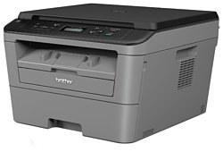
Brother DCP-L2500D
Рейтинг

 Актуальный
Тип устройства
МФУ
Технология печати
лазерная
Макс. формат
A4
Скорость печати
A4
26
Цветность печати
черно-белая
Общие характеристики |
|
|---|---|
Технология печати |
лазерная |
Тип |
лазерный/светодиодный |
Макс. формат |
A4 |
Цветность печати |
|
Сканер |
|
Тип устройства |
МФУ |
Копир |
|
Размещение |
настольный |
Телефон |
|
Факс |
|
Печать фотографий |
|
Принтер |
|
Двусторонняя печать |
|
Прямая печать |
|
Пигментные чернила |
|
Система непрерывной подачи чернил |
|
Печать без полей |
|
Время разогрева |
9 |
Макс, разрешение для ч/б печати |
|
| По Y | 600 |
| По X | 2 400 |
Скорость ч/б печати |
|
| A4 | 26 |
Время выхода первого отпечатка |
|
| Ч/б | 8,5 |
Копир |
|
Макс, количество копий за цикл |
99 |
Шаг масштабирования |
0,01 |
Время выхода первой копии |
10 |
Значение масштаба |
|
| Минимальное | 0,25 |
| Максимальное | 4 |
Макс, разрешение (ч/б) |
|
| По Y | 600 |
| По X | 600 |
Сканер |
|
Тип сканера |
планшетный |
Оттенки серого |
256 |
Глубина цвета |
24 бит |
Макс. формат оригинала |
A4 |
Отправка изображения по e-mail |
|
Стандарт WIA |
|
Стандарт TWAIN |
|
Слайд-адаптер |
|
Макс, размер сканирования |
|
| По Y | 297 |
| По X | 216 |
Разрешение сканера |
|
| По Y (улучшенное) | 19 200 |
| По Y | 2 400 |
| По Х (улучшенное) | 19 200 |
| По Х | 600 |
Расходные материалы |
|
Количество картриджей |
1 |
Ресурс фотобарабана |
12 000 |
Ресурс ч/б картриджа/тонера |
1 200 |
Печать на: |
|
| Этикетках |
|
| Карточках |
|
| Матовой бумаге |
|
| Глянцевой бумаге |
|
| Конвертах |
|
| Пленках |
|
| Фотобумаге |
|
| CD/DVD |
|
| Рулоне |
|
Плотность бумаги |
|
| Максимальная | 163 |
| Минимальная | 60 |
Факс |
|
Цветной |
|
PC Fax |
|
Телефон |
|
Беспроводная трубка |
|
Спикерфон |
|
Стандарт DECT |
|
Автоответчик |
|
Caller ID |
|
АОН |
|
Проводная трубка |
|
Языки управления |
|
| PCL 6 |
|
|
|
|
| PPDS |
|
| PCL 5e |
|
| PCL 5c |
|
| PostScript 3 |
|
| PostScript 2 |
|
| PostScript |
|
Лотки |
|
Емкость лотка ручной подачи |
1 |
Подача бумаги |
|
| Стандартная | 251 |
| Максимальная | 251 |
Вывод бумаги |
|
| Стандартный | 100 |
Финишер |
|
Сортировка со сдвигом |
|
Электронная сортировка |
|
Брошюровщик |
|
Степлер |
|
Сортер |
|
Интерфейсы |
|
Ethernet (RJ-45) |
|
AirPrint |
|
Инфракрасный порт |
|
RS-232 |
|
LPT |
|
Bluetooth |
|
Wi-Fi 802.11n |
|
Wi-Fi |
|
FireWire (IEEE 1394) |
|
Веб-интерфейс |
|
Устройство для чтения карт памяти |
|
USB |
|
Версия USB |
2,0 |
Память/Процессор |
|
Частота процессора |
266 |
Процессор |
ARM9 |
Объем памяти |
32 |
Дополнительная информация |
|
Работа от аккумулятора |
|
Экран |
|
Поддержка ОС |
|
| Windows |
|
| Linux |
|
| Mac OS |
|
| DOS |
|
Потребляемая мощность |
|
| В режиме ожидания | 60 |
| При работе | 480 |
Уровень шума |
|
| При работе | 49 |
| В режиме ожидания | 33 |
Габариты |
|
Вес |
9,7 |
Высота |
267 |
Ширина |
409 |
Глубина |
398 |
Модули
DOCUMENT SCANNER
FRAME L & DRIVE UNIT
ADF & DOCUMENT COVER ASSY
PCB
COVERS & LABELS
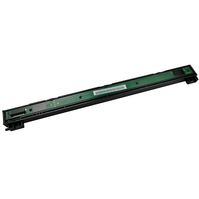
LASER UNIT
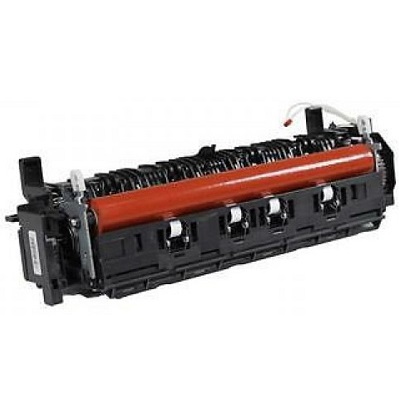
FIXING UNIT
FRAME L
FRAME
PAPER FEEDER
PANEL
PAPER CASSETTE
DX
Детали DOCUMENT SCANNER

| Деталь: | DOCUMENT SCANNER UNIT (SP) |
| Парткод: | LEM323002 |
| Деталь: | DOCUMENT SCANNER UNIT (SP) |
| Парткод: | LEM323001 |
| Деталь: | DOCUMENT SCANNER UNIT (SP) |
| Парткод: | LEM318002 |
| Деталь: | DOCUMENT SCANNER UNIT (SP) |
| Парткод: | LEM326003 |
| Деталь: | DOCUMENT SCANNER UNIT (SP) |
| Парткод: | LEM318001 |
| Деталь: | DOCUMENT SCANNER UNIT (SP) |
| Парткод: | LEM324002 |
| Деталь: | DOCUMENT SCANNER UNIT (SP) |
| Парткод: | LEM325002 |
| Деталь: | FIRST SIDE CIS UNIT |
| Парткод: | LT2868001 |
| Цена: | 2 800 ₽ |
| Деталь: | FIRST SIDE CIS FLAT CABLE |
| Парткод: | LT2869001 |
| Деталь: | ADF CLEANING LABEL |
| Парткод: | LEM159001 |
| Деталь: | ADF CLEANING LABEL |
| Парткод: | LEM162001 |
| Деталь: | MAIN FRAME L ASSY (SP) |
| Парткод: | LEV351001 |
| Деталь: | MAIN FRAME L ASSY (SP) |
| Парткод: | LEV356001 |
| Деталь: | MAIN FRAME L ASSY (SP) |
| Парткод: | LEV354001 |
| Деталь: | MAIN FRAME L ASSY (SP) |
| Парткод: | LEV352001 |
| Деталь: | MAIN FRAME L ASSY (SP) |
| Парткод: | LEV353001 |
| Деталь: | MAIN FRAME L ASSY (SP) |
| Парткод: | LEV355001 |
| Деталь: | MAIN FRAME L ASSY (SP) |
| Парткод: | LEV350001 |
| Деталь: | MAIN FRAME L ASSY (SP) |
| Парткод: | LEV544001 |
| Деталь: | EJECT SENSOR PCB ASSY |
| Парткод: | LV1288001 |
| Деталь: | EJECT SENSOR PCB ASSY |
| Парткод: | LV1467001 |
| Деталь: | FUSER GEAR 67R/40R |
| Парткод: | LY9029001 |
| Цена: | 150 ₽ |
| Деталь: | MAIN MOTOR |
| Парткод: | LY9037001 |
| Цена: | 2 100 ₽ |
| Деталь: | HINGE ASSY L |
| Парткод: | LX4126005 |
| Деталь: | HINGE ASSY L |
| Парткод: | LEM222001 |
| Деталь: | HINGE R |
| Парткод: | LX5180005 |
| Деталь: | HINGE R SUPPORT |
| Парткод: | LS8155005 |
| Деталь: | FFC HOLDER ASSY (SP) |
| Парткод: | LX9717006 |
| Деталь: | DOCUMENT COVER ASSY (SP) |
| Парткод: | LEV276001 |
| Деталь: | DOCUMENT COVER ASSY (SP) |
| Парткод: | LEV277001 |
| Деталь: | DOCUMENT COVER ASSY (SP) |
| Парткод: | LEV278001 |
| Деталь: | DOCUMENT COVER ASSY (SP) |
| Парткод: | LEV279001 |
| Деталь: | HINGE R |
| Парткод: | LX5182004 |
| Деталь: | HINGE L |
| Парткод: | LX5089004 |
| Деталь: | HINGE L SUPPORT |
| Парткод: | LS1690004 |
| Деталь: | EJECT SENSOR PCB ASSY |
| Парткод: | LV1288001 |
| Деталь: | EJECT SENSOR PCB ASSY |
| Парткод: | LV1467001 |
| Деталь: | FUSER GEAR 67R/40R |
| Парткод: | LY9029001 |
| Цена: | 150 ₽ |
| Деталь: | ADF MOTOR |
| Парткод: | LEM202001 |
| Деталь: | MAIN MOTOR |
| Парткод: | LY9037001 |
| Цена: | 2 100 ₽ |
| Деталь: | FIRST SIDE DOCUMENT SCANNING POSITION SENSOR PCB ASSY |
| Парткод: | LG6753001 |
| Деталь: | FIRST SIDE DOCUMENT SCANNING |
| Парткод: | LG6753001 |
| Деталь: | POSITION SENSOR PCB ASSY FIRST SIDE DOCUMENT SCANNING |
| Парткод: | LG6753001 |
| Деталь: | POSITION SENSOR PCB ASSY SECOND SIDE DOCUMENT |
| Парткод: | LG6753001 |
| Деталь: | SCANNING POSITION SENSOR PCB SECOND SIDE DOCUMENT |
| Парткод: | LG6753001 |
| Деталь: | SCANNING POSITION SENSOR PCB ADF COVER/DOCUMENT |
| Парткод: | LT1120001 |
| Деталь: | DETECTION SENSOR PCB ASSY ADF COVER/DOCUMENT |
| Парткод: | LT1120001 |
| Деталь: | ADF COVER/DOCUMENT DETECTION SENSOR PCB ASSY |
| Парткод: | LT1120001 |
| Деталь: | ADF COVER/DOCUMENT |
| Парткод: | LT1120001 |
| Деталь: | DETECTION SENSOR PCB ASSY DOCUMENT FEED ROLLER ASSY 1 |
| Парткод: | LX8675001 |
| Деталь: | DOCUMENT FEED ROLLER ASSY 1 |
| Парткод: | LX8675001 |
| Деталь: | ADF SEPARATION PAD HOLDERASSY |
| Парткод: | LX9751001 |
| Деталь: | ADF SEPARATION PAD HOLDER |
| Парткод: | LX9751001 |
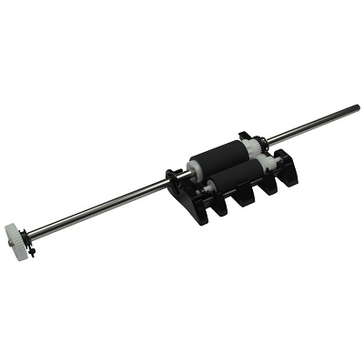
| Деталь: | DOCUMENT SEPARATE ROLLER |
| Парткод: | LX9296001 |
| Цена: | 1 700 ₽ |
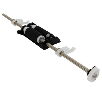
| Деталь: | DOCUMENT SEPARATE ROLLER |
| Парткод: | LX9297001 |
| Цена: | 1 600 ₽ |
| Деталь: | GEAR COVER |
| Парткод: | LEM026002 |
| Деталь: | GEAR COVER |
| Парткод: | LEM026001 |
| Деталь: | HINGE ARM |
| Парткод: | LX5183004 |
| Деталь: | ADF COVER ASSY |
| Парткод: | LEM033002 |
| Деталь: | ADF COVER ASSY |
| Парткод: | LEM033001 |
| Деталь: | ADF COVER ASSY |
| Парткод: | LEM027002 |
| Деталь: | ADF DOCUMENT SUPPORT |
| Парткод: | LEM029003 |
| Деталь: | ADF DOCUMENT SUPPORT |
| Парткод: | LEM029001 |
| Деталь: | ADF DOCUMENT SUPPORT |
| Парткод: | LEM029012 |
| Деталь: | SECOND SIDE CIS UNIT |
| Парткод: | LT2868001 |
| Цена: | 2 800 ₽ |
| Деталь: | SECOND SIDE CIS FLAT CABLE |
| Парткод: | LT2888001 |
| Деталь: | CIS SPACER |
| Парткод: | LX9030001 |
| Деталь: | ADF DOCUMENT OUTPUT SUPPORT FLAP |
| Парткод: | LEM020001 |
| Деталь: | ADF DOCUMENT OUTPUT SUPPORT FLAP |
| Парткод: | LEM020002 |
| Деталь: | HINGE ARM R |
| Парткод: | LS8141005 |
| Деталь: | MAIN PCB ASSY |
| Парткод: | LT3268001 |
| Деталь: | MAIN PCB ASSY |
| Парткод: | LT3271001 |
| Деталь: | MAIN PCB ASSY |
| Парткод: | LT3172001 |
| Деталь: | MAIN PCB ASSY |
| Парткод: | LT3512001 |
| Деталь: | MAIN PCB ASSY |
| Парткод: | LT3221001 |
| Деталь: | MAIN PCB ASSY |
| Парткод: | LT3171001 |
| Деталь: | MAIN PCB ASSY |
| Парткод: | LT3168001 |
| Деталь: | MAIN PCB ASSY* |
| Парткод: | LT3167001 |
| Деталь: | MAIN PCB ASSY* |
| Парткод: | LT3751001 |
| Деталь: | MAIN PCB ASSY |
| Парткод: | LT3273001 |
| Деталь: | MAIN PCB ASSY |
| Парткод: | LT3276001 |
| Деталь: | MAIN PCB ASSY |
| Парткод: | LT3829001 |
| Деталь: | MAIN PCB ASSY |
| Парткод: | LT3416001 |
| Деталь: | MAIN PCB ASSY |
| Парткод: | LT3842001 |
| Деталь: | MAIN PCB ASSY |
| Парткод: | LT3166001 |
| Деталь: | MAIN PCB ASSY |
| Парткод: | LT3609001 |
| Деталь: | MAIN PCB ASSY |
| Парткод: | LT3288001 |
| Деталь: | MAIN PCB ASSY* |
| Парткод: | LT3219001 |
| Деталь: | MAIN PCB ASSY* |
| Парткод: | LT3752001 |
| Деталь: | MAIN PCB ASSY* |
| Парткод: | LT3165001 |
| Деталь: | MAIN PCB ASSY* |
| Парткод: | LT3753001 |
| Деталь: | MODEM PCB ASSY |
| Парткод: | LT3279024 |
| Деталь: | MODEM PCB ASSY |
| Парткод: | LT3292001 |
| Деталь: | MODEM PCB ASSY |
| Парткод: | LT3293002 |
| Деталь: | MODEM PCB ASSY |
| Парткод: | LT3294003 |
| Деталь: | LOW-VOLTAGE POWER SUPPLY PCB ASSY |
| Парткод: | LT3656001 |
| Деталь: | LOW-VOLTAGE POWER SUPPLY PCB ASSY |
| Парткод: | LT3630001 |
| Деталь: | LOW-VOLTAGE POWER SUPPLY PCB ASSY |
| Парткод: | LT3521001 |
| Деталь: | LOW-VOLTAGE POWER SUPPLY PCB ASSY |
| Парткод: | LT2884001 |
| Деталь: | LOW-VOLTAGE POWER SUPPLY PCB ASSY |
| Парткод: | LT3563001 |
| Деталь: | LOW-VOLTAGE POWER SUPPLY |
| Парткод: | LT2889001 |
| Деталь: | LOW-VOLTAGE POWER SUPPLY PCB ASSY |
| Парткод: | LT3281001 |
| Деталь: | LOW-VOLTAGE POWER SUPPLY PCB ASSY |
| Парткод: | LT3552001 |
| Деталь: | LOW-VOLTAGE POWER SUPPLY PCB ASSY |
| Парткод: | LT3548001 |
| Деталь: | LOW-VOLTAGE POWER SUPPLY PCB ASSY |
| Парткод: | LT3533001 |
| Деталь: | LOW-VOLTAGE POWER SUPPLY PCB ASSY |
| Парткод: | LT3624001 |
| Деталь: | LOW-VOLTAGE POWER SUPPLY PCB ASSY |
| Парткод: | LT3625001 |
| Деталь: | LOW-VOLTAGE POWER SUPPLY PCB ASSY |
| Парткод: | LT3626001 |
| Деталь: | LOW-VOLTAGE POWER SUPPLY PCB ASSY |
| Парткод: | LT3251001 |
| Деталь: | LOW-VOLTAGE POWER SUPPLY PCB ASSY |
| Парткод: | LT2889001 |
| Деталь: | LOW-VOLTAGE POWER SUPPLY PCB ASSY |
| Парткод: | LT3655001 |
| Деталь: | LOW-VOLTAGE POWER SUPPLY PCB ASSY |
| Парткод: | LT3255001 |
| Деталь: | HIGH-VOLTAGE POWER SUPPLY PCB ASSY |
| Парткод: | LV1241001 |
| Деталь: | HIGH-VOLTAGE POWER SUPPLY PCB ASSY |
| Парткод: | LV1243001 |
| Деталь: | HIGH-VOLTAGE POWER SUPPLY |
| Парткод: | LV1243001 |
| Деталь: | HIGH-VOLTAGE POWER SUPPLY |
| Парткод: | LV1241001 |
| Деталь: | MODEM FLAT CABLE |
| Парткод: | LT2881001 |
| Деталь: | JOINT COVER ASSY (SP) |
| Парткод: | LEM701002 |
| Деталь: | JOINT COVER ASSY (SP) |
| Парткод: | LEM701001 |
| Деталь: | JOINT COVER ASSY (SP) |
| Парткод: | LEM701003 |
| Деталь: | JOINT COVER ASSY (SP) |
| Парткод: | LEM703001 |
| Деталь: | JOINT COVER ASSY (SP) |
| Парткод: | LEM703002 |
| Деталь: | JOINT COVER ASSY (SP) |
| Парткод: | LEM702001 |
| Деталь: | JOINT COVER ASSY (SP) |
| Парткод: | LEM702002 |
| Деталь: | FRONT COVER ASSY |
| Парткод: | LEM275002 |
| Деталь: | FRONT COVER ASSY |
| Парткод: | LEM275001 |
| Деталь: | FRONT COVER ASSY |
| Парткод: | LEM283001 |
| Деталь: | FRONT COVER ASSY |
| Парткод: | LEM003001 |
| Деталь: | FRONT COVER ASSY |
| Парткод: | LEM003002 |
| Деталь: | FRONT COVER ASSY |
| Парткод: | LEM283002 |
| Деталь: | FRONT COVER ASSY |
| Парткод: | LEM283003 |
| Деталь: | FRONT COVER ASSY |
| Парткод: | LEM003003 |
| Деталь: | FRONT COVER ASSY |
| Парткод: | LEM273003 |
| Деталь: | FRONT COVER ASSY |
| Парткод: | LEM273001 |
| Деталь: | FRONT COVER ASSY |
| Парткод: | LEM273002 |
| Деталь: | SUPPORT FLAP |
| Парткод: | LEM005002 |
| Деталь: | SUPPORT FLAP |
| Парткод: | LEM005001 |
| Деталь: | SUPPORT FLAP |
| Парткод: | LEM005003 |
| Деталь: | INNER CHUTE ASSY |
| Парткод: | LY9130002 |
| Деталь: | INNER CHUTE ASSY |
| Парткод: | LY9130003 |
| Деталь: | INNER CHUTE ASSY |
| Парткод: | LY9130001 |
| Деталь: | FUSER COVER |
| Парткод: | LY9136001 |
| Деталь: | OUTER CHUTE ASSY |
| Парткод: | LY9146001 |
| Деталь: | BACK COVER ASSY |
| Парткод: | LJB498002 |
| Деталь: | BACK COVER |
| Парткод: | LJB273001 |
| Деталь: | BACK COVER |
| Парткод: | LJB273002 |
| Деталь: | BACK COVER |
| Парткод: | LY9148001 |
| Деталь: | BACK COVER |
| Парткод: | LY9148002 |
| Деталь: | BACK COVER |
| Парткод: | LY9148003 |
| Деталь: | BACK COVER ASSY |
| Парткод: | LJB498001 |
| Деталь: | BACK COVER ASSY |
| Парткод: | LY9502001 |
| Деталь: | SIDE COVER L |
| Парткод: | LEM009002 |
| Деталь: | SIDE COVER L |
| Парткод: | LEM009001 |
| Деталь: | SIDE COVER L |
| Парткод: | LEM009003 |
| Деталь: | SIDE COVER L |
| Парткод: | LEM230001 |
| Деталь: | SIDE COVER L |
| Парткод: | LEM230002 |
| Деталь: | SIDE COVER R |
| Парткод: | LEM880002 |
| Деталь: | SIDE COVER R |
| Парткод: | LEM880001 |
| Деталь: | SIDE COVER R |
| Парткод: | LEM148001 |
| Деталь: | SIDE COVER R |
| Парткод: | LEM010001 |
| Деталь: | SIDE COVER R |
| Парткод: | LEM010002 |
| Деталь: | SIDE COVER R |
| Парткод: | LEM148002 |
| Деталь: | SIDE COVER R |
| Парткод: | LEM148003 |
| Деталь: | SIDE COVER R |
| Парткод: | LEM010003 |
| Деталь: | SPEAKER UNIT |
| Парткод: | LT3186001 |
| Деталь: | PULL ARM L |
| Парткод: | LF6145001 |
| Деталь: | PULL ARM R |
| Парткод: | LF6146001 |
| Деталь: | PULL ARM GUIDE |
| Парткод: | LS0340001 |
| Деталь: | PULL ARM GUIDE |
| Парткод: | LEM154001 |
| Деталь: | LOCK CLAW |
| Парткод: | LF6148001 |
| Деталь: | PULL ARM SPRING |
| Парткод: | LEM796001 |
| Деталь: | CORD HOOK |
| Парткод: | LF6745002 |
| Деталь: | LAN PORT CAP |
| Парткод: | LY0872001 |
| Деталь: | EXT CAP |
| Парткод: | LE8842001 |
| Деталь: | MJ COVER EXT |
| Парткод: | UF5745000 |
| Деталь: | LABEL H CAUTION FRONT 21X33 |
| Парткод: | LEM160001 |
| Деталь: | LABEL H CAUTION FRONT US 21X41 |
| Парткод: | LEM158001 |
| Деталь: | LABEL H CAUTION FRONT 21X33 |
| Парткод: | LEM158001 |
| Деталь: | LABEL H CAUTION REAR 12X95 |
| Парткод: | LY9330001 |
| Деталь: | LOWER HANDSET COVER |
| Парткод: | LX5296011 |
| Деталь: | LOWER HANDSET COVER |
| Парткод: | LX5296012 |
| Деталь: | UPPER HANDSET COVER |
| Парткод: | LX5297011 |
| Деталь: | UPPER HANDSET COVER |
| Парткод: | LX5297012 |
| Деталь: | HOOK SWITCH PCB ASSY |
| Парткод: | LT1764001 |
| Деталь: | ACTUATOR HOOK |
| Парткод: | LS0018011 |
| Деталь: | LASER UNIT(SP) |
| Парткод: | LY9282001 |
| Цена: | 8 400 ₽ |
| Деталь: | LASER UNIT(SP) |
| Парткод: | LY9955001 |
| Цена: | 8 400 ₽ |
| Деталь: | LASER UNIT FLAT CABLE |
| Парткод: | LV1232001 |
| Цена: | 310 ₽ |
| Деталь: | FUSER UNIT(SP) |
| Парткод: | LY9388001 |
| Деталь: | FUSER UNIT(SP) |
| Парткод: | LY9389001 |
| Деталь: | FUSER UNIT(SP) |
| Парткод: | LJB343001 |
| Деталь: | FUSER UNIT(SP) |
| Парткод: | LY9467001 |
| Деталь: | FUSER UNIT(SP) |
| Парткод: | LJB886001 |
| Деталь: | TAPTITE PAN B M4X14 |
| Парткод: | LJ0395001 |
| Деталь: | ENCODER STRIP GUARD FILM |
| Парткод: | LJB858001 |
| Цена: | 9 000 ₽ |
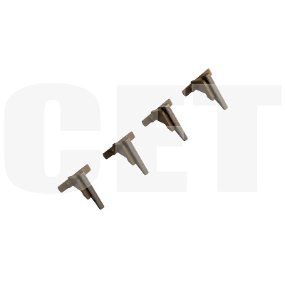
| Деталь: | Палец отделения бумаги от тефлонового вала |
| Парткод: | CET6763 |
| Цена: | 390 ₽ |
| Деталь: | FAN |
| Парткод: | LY9348001 |
| Цена: | 1 400 ₽ |
| Деталь: | FILTER |
| Парткод: | LY2141001 |
| Цена: | 350 ₽ |
| Деталь: | HVPS FLAT CABLE |
| Парткод: | LV1226001 |
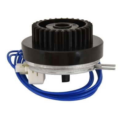
| Деталь: | T1 CLUTCH |
| Парткод: | LY2144001 |
| Цена: | 700 ₽ |
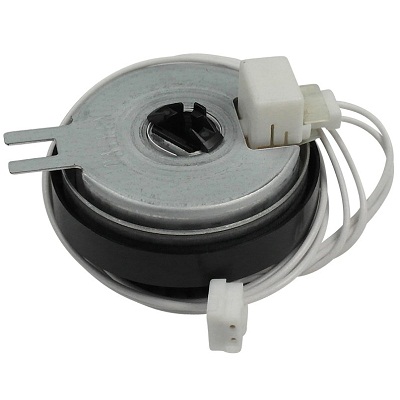
| Деталь: | REGISTRATION CLUTCH |
| Парткод: | LY2150001 |
| Цена: | 700 ₽ |
| Деталь: | WIRE ESS L AN PCB* |
| Парткод: | IT3808001 |
| Деталь: | WIRELESS LAN PCB* |
| Парткод: | LT3652001 |
| Деталь: | WIRE CSC L AN PCR* |
| Парткод: | IT3Q0Q001 |
| Деталь: | WIRELESS LAN PCB* |
| Парткод: | LT3808001 |
| Деталь: | WIRELESS LAN PCB |
| Парткод: | LT3652001 |
| Деталь: | WIRELESS LAN PCB* |
| Парткод: | LT3753001 |
| Деталь: | GASKFT* |
| Парткод: | IV1394001 |
| Деталь: | GASKFT |
| Парткод: | IV1394001 |
| Деталь: | GASKET* |
| Парткод: | LV1394001 |
| Деталь: | GASKET |
| Парткод: | LV1394001 |
| Деталь: | NEW TONER SENSOR PCB ASSY |
| Парткод: | LT2867001 |
| Деталь: | FLAT CABLE SPONGE |
| Парткод: | LY9721001 |
| Деталь: | REGISTRATION FRONT/REAR |
| Парткод: | LY9527001 |
| Деталь: | ACTUATOR HOLDER ASSY REGISTRATION FRONT/REAR |
| Парткод: | LY9326001 |
| Деталь: | ACTUATOR HOLDER ASSY REGISTRATION FRONT/REAR |
| Парткод: | LY9527001 |
| Деталь: | ACTUATOR HOLDER ASSY REGISTRATION FRONT/REAR ACTUATOR HOLDER ASSY |
| Парткод: | LY9326001 |
| Деталь: | PANEL UNIT |
| Парткод: | LEM225001 |
| Деталь: | PANEL UNIT |
| Парткод: | LEM227001 |
| Деталь: | PANEL UNIT |
| Парткод: | LEM089001 |
| Деталь: | PANEL UNIT |
| Парткод: | LEM271001 |
| Деталь: | PANEL UNIT |
| Парткод: | LEM105001 |
| Деталь: | PANEL UNIT |
| Парткод: | LEM107001 |
| Деталь: | PANEL UNIT |
| Парткод: | LEV049001 |
| Деталь: | PANEL UNIT |
| Парткод: | LEM277001 |
| Деталь: | PANEL UNIT |
| Парткод: | LEM904001 |
| Деталь: | PANEL UNIT |
| Парткод: | LEM108001 |
| Деталь: | PANEL UNIT |
| Парткод: | LEM214001 |
| Деталь: | PANEL UNIT |
| Парткод: | LEM217001 |
| Деталь: | PANEL UNIT |
| Парткод: | LEM219001 |
| Деталь: | PANEL UNIT |
| Парткод: | LEV444001 |
| Деталь: | PANEL UNIT |
| Парткод: | LEM909001 |
| Деталь: | PANEL UNIT |
| Парткод: | LEV031001 |
| Деталь: | PANEL UNIT |
| Парткод: | LEV035001 |
| Деталь: | PANEL UNIT |
| Парткод: | LEM586001 |
| Деталь: | PANEL UNIT |
| Парткод: | LEV484001 |
| Деталь: | PANEL UNIT |
| Парткод: | LEV490001 |
| Деталь: | PANEL UNIT |
| Парткод: | LEV496001 |
| Деталь: | PANEL UNIT |
| Парткод: | LEV614001 |
| Деталь: | PANEL UNIT |
| Парткод: | LEV522001 |
| Деталь: | PANEL UNIT |
| Парткод: | LEV527001 |
| Деталь: | PANEL UNIT |
| Парткод: | LEM052001 |
| Деталь: | PANEL UNIT |
| Парткод: | LEM675001 |
| Деталь: | PANEL UNIT |
| Парткод: | LEM110001 |
| Деталь: | PANEL UNIT |
| Парткод: | LEM681001 |
| Деталь: | PANEL UNIT |
| Парткод: | LEM848001 |
| Деталь: | PANEL UNIT |
| Парткод: | LEM686001 |
| Деталь: | PANEL UNIT |
| Парткод: | LEM691001 |
| Деталь: | PANEL UNIT |
| Парткод: | LEV053001 |
| Деталь: | PANEL UNIT |
| Парткод: | LEV041001 |
| Деталь: | PANEL UNIT |
| Парткод: | LEM839001 |
| Деталь: | PANEL UNIT |
| Парткод: | LEV113001 |
| Деталь: | PANEL UNIT |
| Парткод: | LEM223001 |
| Деталь: | PANEL UNIT |
| Парткод: | LEM694001 |
| Деталь: | PANEL UNIT |
| Парткод: | LEM697001 |
| Деталь: | PANEL UNIT |
| Парткод: | LEM842001 |
| Деталь: | PANEL UNIT |
| Парткод: | LEM907001 |
| Деталь: | PANEL UNIT |
| Парткод: | LEM849001 |
| Деталь: | PANEL UNIT |
| Парткод: | LEM803001 |
| Деталь: | PANEL UNIT |
| Парткод: | LEV080001 |
| Деталь: | PANEL UNIT |
| Парткод: | LEM709001 |
| Деталь: | PANEL UNIT |
| Парткод: | LEM280001 |
| Деталь: | PANEL UNIT |
| Парткод: | LEM933001 |
| Деталь: | PANEL UNIT |
| Парткод: | LEM035001 |
| Деталь: | PANEL UNIT |
| Парткод: | LEM113001 |
| Деталь: | PANEL UNIT |
| Парткод: | LEM944001 |
| Деталь: | LCD SHEET |
| Парткод: | LEM207001 |
| Деталь: | LCD SHEET |
| Парткод: | LEM210001 |
| Деталь: | LCD SHEET |
| Парткод: | LEM213001 |
| Деталь: | LCD SHEET |
| Парткод: | LEM094001 |
| Деталь: | LCD SHEET |
| Парткод: | LEM815001 |
| Деталь: | LCD SHEET |
| Парткод: | LEM673001 |
| Деталь: | LCD SHEET |
| Парткод: | LEM221001 |
| Деталь: | LCD SHEET |
| Парткод: | LEM827001 |
| Деталь: | LCD SHEET |
| Парткод: | LEM133001 |
| Деталь: | LCD SHEET |
| Парткод: | LEM831001 |
| Деталь: | LCD SHEET |
| Парткод: | LEM070001 |
| Деталь: | LCD SHEET |
| Парткод: | LEV105001 |
| Деталь: | PRINTED PANEL COVER |
| Парткод: | LEM208001 |
| Деталь: | PRINTED PANEL COVER |
| Парткод: | LEM623001 |
| Деталь: | PRINTED PANEL COVER |
| Парткод: | LEM629001 |
| Деталь: | PRINTED PANEL COVER |
| Парткод: | LEM345001 |
| Деталь: | PRINTED PANEL COVER |
| Парткод: | LEM344001 |
| Деталь: | PRINTED PANEL COVER |
| Парткод: | LEM624001 |
| Деталь: | PRINTED PANEL COVER |
| Парткод: | LEM821001 |
| Деталь: | PRINTED PANEL COVER |
| Парткод: | LEM630001 |
| Деталь: | PRINTED PANEL COVER |
| Парткод: | LEM347001 |
| Деталь: | PRINTED PANEL COVER |
| Парткод: | LEM657001 |
| Деталь: | PRINTED PANEL COVER |
| Парткод: | LEM653001 |
| Деталь: | PRINTED PANEL COVER |
| Парткод: | LEM238001 |
| Деталь: | PRINTED PANEL COVER |
| Парткод: | LEM338001 |
| Деталь: | PRINTED PANEL COVER |
| Парткод: | LEM654001 |
| Деталь: | PRINTED PANEL COVER |
| Парткод: | LEM829001 |
| Деталь: | PRINTED PANEL COVER |
| Парткод: | LEM656001 |
| Деталь: | PRINTED PANEL COVER |
| Парткод: | LEM339001 |
| Деталь: | PRINTED PANEL COVER |
| Парткод: | LEM333001 |
| Деталь: | ADDRESS LABEL |
| Парткод: | LEM062001 |
| Деталь: | PANEL COVER ASSY |
| Парткод: | LEM065001 |
| Деталь: | PANEL COVER ASSY |
| Парткод: | LEM228001 |
| Деталь: | PANEL COVER ASSY |
| Парткод: | LEM121001 |
| Деталь: | PANEL COVER ASSY |
| Парткод: | LEM064001 |
| Деталь: | PANEL COVER ASSY |
| Парткод: | LEM921001 |
| Деталь: | PANEL COVER ASSY |
| Парткод: | LEV182001 |
| Деталь: | PANEL COVER ASSY |
| Парткод: | LEM922001 |
| Деталь: | PANEL COVER ASSY |
| Парткод: | LEM211001 |
| Деталь: | PANEL COVER ASSY |
| Парткод: | LEV438001 |
| Деталь: | PANEL COVER ASSY |
| Парткод: | LEM666001 |
| Деталь: | PANEL COVER ASSY |
| Парткод: | LEM668001 |
| Деталь: | PANEL COVER ASSY |
| Парткод: | LEM667001 |
| Деталь: | PANEL COVER ASSY |
| Парткод: | LEM452001 |
| Деталь: | PANEL COVER ASSY |
| Парткод: | LEV460001 |
| Деталь: | PANEL COVER ASSY |
| Парткод: | LEV461001 |
| Деталь: | PANEL COVER ASSY |
| Парткод: | LEV608001 |
| Деталь: | PANEL COVER ASSY |
| Парткод: | LEV493001 |
| Деталь: | PANEL COVER ASSY |
| Парткод: | LEV462001 |
| Деталь: | PANEL COVER ASSY |
| Парткод: | LEM054001 |
| Деталь: | PANEL COVER ASSY |
| Парткод: | LEM353001 |
| Деталь: | PANEL COVER ASSY |
| Парткод: | LEM112001 |
| Деталь: | PANEL COVER ASSY |
| Парткод: | LEM352001 |
| Деталь: | PANEL COVER ASSY |
| Парткод: | LEM360001 |
| Деталь: | PANEL COVER ASSY |
| Парткод: | LEM354001 |
| Деталь: | PANEL COVER ASSY |
| Парткод: | LEM357001 |
| Деталь: | PANEL COVER ASSY |
| Парткод: | LEM361001 |
| Деталь: | PANEL COVER ASSY |
| Парткод: | LEM350001 |
| Деталь: | PANEL COVER ASSY |
| Парткод: | LEM358001 |
| Деталь: | PANEL COVER ASSY |
| Парткод: | LEM351001 |
| Деталь: | PANEL COVER ASSY |
| Парткод: | LEM224001 |
| Деталь: | PANEL COVER ASSY |
| Парткод: | LEM355001 |
| Деталь: | PANEL COVER ASSY |
| Парткод: | LEM356001 |
| Деталь: | PANEL COVER ASSY |
| Парткод: | LEM359001 |
| Деталь: | PANEL COVER ASSY |
| Парткод: | LEM923001 |
| Деталь: | PANEL COVER ASSY |
| Парткод: | LEM924001 |
| Деталь: | PANEL COVER ASSY |
| Парткод: | LEV184001 |
| Деталь: | PANEL COVER ASSY |
| Парткод: | LEM925001 |
| Деталь: | PANEL COVER ASSY |
| Парткод: | LEM926001 |
| Деталь: | PANEL COVER ASSY |
| Парткод: | LEV185001 |
| Деталь: | PANEL PCB ASSY |
| Парткод: | LT2896002 |
| Деталь: | PANEL PCB ASSY |
| Парткод: | LT3173001 |
| Деталь: | PANEL PCB ASSY |
| Парткод: | LT3265001 |
| Деталь: | PANEL PCB ASSY |
| Парткод: | LT2878001 |
| Деталь: | PANEL PCB ASSY |
| Парткод: | LT3266001 |
| Деталь: | PANEL PCB ASSY |
| Парткод: | LT2896001 |
| Деталь: | LCD |
| Парткод: | A62261001 |
| Деталь: | LCD |
| Парткод: | A62258001 |
| Деталь: | LCD |
| Парткод: | A62260001 |
| Деталь: | LCD |
| Парткод: | A63539001 |
| Деталь: | LCD |
| Парткод: | A62257001 |
| Деталь: | LCD SHEET |
| Парткод: | LEM216001 |
| Деталь: | LCD SHEET |
| Парткод: | LEM218001 |
| Деталь: | LCD SHEET |
| Парткод: | LEM220001 |
| Деталь: | LCD SHEET |
| Парткод: | LEV439001 |
| Деталь: | LCD SHEET |
| Парткод: | LEM453001 |
| Деталь: | LCD SHEET |
| Парткод: | LEV466001 |
| Деталь: | LCD SHEET |
| Парткод: | LEV467001 |
| Деталь: | LCD SHEET |
| Парткод: | LEM060001 |
| Деталь: | LCD SHEET |
| Парткод: | LEM843001 |
| Деталь: | LCD SHEET |
| Парткод: | LEM908001 |
| Деталь: | LCD SHEET |
| Парткод: | LEM850001 |
| Деталь: | LCD SHEET |
| Парткод: | LEM804001 |
| Деталь: | LCD SHEET |
| Парткод: | LEV081001 |
| Деталь: | TOUCH PANEL ASSY |
| Парткод: | LEM048001 |
| Деталь: | PAPER TRAY |
| Парткод: | LEV539002 |
| Деталь: | PAPER TRAY |
| Парткод: | LEV539001 |
| Цена: | 3 300 ₽ |
| Деталь: | PAPER TRAY |
| Парткод: | LEM132001 |
| Деталь: | PAPER TRAY |
| Парткод: | LEM084001 |
| Деталь: | PAPER TRAY |
| Парткод: | LEM132002 |
| Деталь: | PAPER TRAY |
| Парткод: | LEM084002 |
| Деталь: | PAPER TRAY |
| Парткод: | LEM132003 |
| Деталь: | PAPER TRAY |
| Парткод: | LEM084003 |
| Деталь: | DUPLEX TRAY A4 |
| Парткод: | LJB536011 |
| Деталь: | DUPLEX TRAY A4 |
| Парткод: | LJB536012 |
| Деталь: | DUPLEX TRAY A4 |
| Парткод: | LY2452011 |
| Деталь: | DUPLEX TRAY A4 |
| Парткод: | LY2452012 |
| Деталь: | DUPLEX TRAY LTR |
| Парткод: | LY2166012 |
| Деталь: | DUPLEX TRAY A4 |
| Парткод: | LY2452015 |
| Деталь: | DUPLEX TRAY LTR |
| Парткод: | LY2166013 |
| Деталь: | DUPLEX TRAY LTR |
| Парткод: | LY2166011 |
Коды ошибок
0201
0300
0305
0401
0405
0501
0502
0503
0504
0505
0506
050A
050B
050C
050F
0600
0800
0900
0A02
0B01
0B02
4000
4200
4B01
4C01
4D01
4E01
4F01
6001
6004
6101
6801
6901
6902
6A00
6F00
7000
7100
7300
7700
7C00
8903
8904
8A01
8C00
8E01
8E02
9002
9302
9307
9701
A000
A200
A300
A400
A500
A600
A700
AC00
AD00
AF00
B000
BB00
BC00
BD00
BF00
C700
C800
D100
D200
D800
D900
DA00
E000
E100
E500
E600
E701
E702
F900
Описание
| Error code: | 0201 |
| Display: | Print Unable 02 Turn the power off and then back on again. |
| Description: | Head 2 is abnormally hot. Head 2 temperature has reached 58°C and above. |
| Causes: | Thermistor (Head) has a problem. Flexible Cable has short circuitted or cut-line. |
| Remedy: | Check Flexible Cable connection around Head Head replacement |
| Error code: | 0300 |
| Display: | POLYGON MOTOR |
| Description: | Polygon motor malfunction |
| Causes: | • The polygon motor does not rotate evenly even after the lapse of a given period of time after it has been started. • The motor lock signal remains HIGH for a given period of consecutive time while the polygon motor is being rotated. |
| Remedy: | 1 Check the cable and connector for proper connection and correct as necessary. - - 2 Change PH unit. - - 3 Change PRCB. - - |
| Error code: | 0305 |
| Description: | ROM Checksum Failure |
| Remedy: | Replace the system board. |
| Error code: | 0401 |
| Display: | Print Unable 04 Turn the power off and then back on again. |
| Description: | BD sensor 1 damaged. |
| Remedy: | 1 Connection failure of the polygon motor harness Reconnect the polygon motor harness. 2 Laser unit failure Replace the laser unit. 3 Main PCB failure Replace the main PCB ASSY. |
| Error code: | 0405 |
| Description: | Cannot detect the synchronized signal of the polygon motor for the laser unit (first time). |
| Remedy: | 1 Connection failure of the laser unit flat cable Reconnect the laser unit flat cable. 2 Laser unit flat cable failure Replace the laser unit flat cable. 3 Laser unit failure Replace the laser unit. 4 Main PCB failure Replace the main PCB ASSY. |
| Error code: | 0501 |
| Display: | FUSER ERROR |
| Description: | Fusing Pressure Roller warm-up failure • The Fusing Pressure Roller Thermistor/1 (TH2) fails to raise a given degree of temperature even after the lapse of a given period of time after the Fusing Pressure Heater Lamp (H3) is turned ON. • The detected temperature of the Fusing Pressure Roller Thermistor/1 (TH2) is lower for a given level of degree than one of the Heating Roller Thermistor/1 (TH1) after the Front Door is opened or closed, the Main Power Switch is turned ON or TROUBLE RESET is implemented. |
| Causes: | 1 Connection failure of the center or side thermistor harness of the fuser unit 2 Connection failure of the heater harness of the fuser unit 3 Harness connection failure of the eject sensor PCB 4 Harness connection failure of the low-voltage power supply PCB 5 Eject sensor PCB failure 6 Fuser unit failure 7 Low-voltage power supply PCB failure 8 Main PCB failure |
| Remedy: | 1 Check the Fusing Unit for correct installation (whether it is secured in position). 2 Check the Fusing Unit, PWB-M and PU1 for proper connection and correct or change as necessary. 3 Change Fusing Unit. 4 Change PWB-M. 5 Change PU1. |
| Error code: | 0502 |
| Display: | Thermistor failure CODE (0502) Turn power off, on |
| Description: | 0502 Thermistor Failure, 0510 Fuser Failure, and 0520 Fuser Failure 0502 Thermistor Failure The temperature detected by the thermistor does not reach an expected level after the warm-up cycle starts. |
| Causes: | • Fuser, PL4.0.13 • Engine Control Board, PL13.0.20 • Power Supply, PL13.0.17 |
| Remedy: | 1 Check that the Fuser is installed correctly. Does the problem persist? Go to step 2. Complete. 2 Check the Engine Control Board connectors P/J2, P/J3, and P/J6. Are the connectors seated properly? Go to step 3 Reseat the connectors. If the problem persists, go to step 3. 3 Check the Low Voltage Power Supply connectors CN3, CN5, and CN7. Are the connectors seated properly? Go to step 4. Reseat the connectors. If the problem persists, go to step 4. 4 Replace the Fuser (8-9). Does the problem persist? Go to step 5. Complete. 5 Replace the Engine Control Board. Does the problem persist? Go to step 6. Complete. 6 Replace the Power Supply. Complete. |
| Error code: | 0503 |
| Display: | TERMISTOR2 |
| Description: | Thermistor resistance failure |
| Causes: | • The difference between the temperature detected by thermistor/1 and that detected by thermistor/2 exceeds a predetermined value. |
| Remedy: | 1 Change fuser unit. - - 2 For C110: 1. Main switch is turned ON. 2. Open the top cover. 3. Press the following keys in this order. ROTATE TONER key -ATTENTION key - ATTENTION key - ROTATE TONER key. 4. Main switch is turned OFF/ON. For C130n: 1. Main switch is turned ON. 2. Execute [SERVICE MENU] - [FUSER UNLOCK]. See P.103 - - 3 Change PRCB. - - 4 Change DCPU. - - |
| Error code: | 0504 |
| Display: | Print Unable 05 Turn the power off and then back on again. |
| Description: | After the center thermistor of the fuser unit was normally heated, it detected a temperature lower than the specified value. |
| Causes: | 1 Connection failure of the center or side thermistor harness of the fuser unit 2 Connection failure of the heater harness of the fuser unit 3 Harness connection failure of the eject sensor PCB 4 Harness connection failure of the low-voltage power supply PCB 5 Eject sensor PCB failure 6 Fuser unit failure 7 Low-voltage power supply PCB failure 8 Main PCB failure |
| Remedy: | < User Check > - Turn OFF the power switch. After several seconds, turn ON the power again and check that this error is reset. 1 Connection failure of the center or side thermistor harness of the fuser unit Reconnect the harness of the center thermistor or side thermistor of the fuser unit. 2 Connection failure of the heater harness of the fuser unit Reconnect the heater harness of the fuser unit. 3 Connection failure of the eject sensor PCB harness Reconnect the eject sensor PCB harness. 4 Connection failure of the low-voltage power supply PCB harness Reconnect the low-voltage power supply PCB harness. 5 Eject sensor PCB failure Replace the eject sensor PCB ASSY. 6 Fuser unit failure Replace the fuser unit. 7 Low-voltage power supply PCB failure Replace the low-voltage power supply PCB unit. 8 Main PCB failure Replace the main PCB ASSY. |
| Error code: | 0505 |
| Display: | Print Unable 05 Turn the power off and then back on again. |
| Description: | The center thermistor of the fuser unit detected a temperature rise greater than the specified value within a set period of time. |
| Causes: | 1 Connection failure of the center or side thermistor harness of the fuser unit 2 Connection failure of the heater harness of the fuser unit 3 Harness connection failure of the eject sensor PCB 4 Harness connection failure of the low-voltage power supply PCB 5 Eject sensor PCB failure 6 Fuser unit failure 7 Low-voltage power supply PCB failure 8 Main PCB failure |
| Remedy: | < User Check > - Turn OFF the power switch. After several seconds, turn ON the power again and check that this error is reset. 1 Connection failure of the center or side thermistor harness of the fuser unit Reconnect the harness of the center thermistor or side thermistor of the fuser unit. 2 Connection failure of the heater harness of the fuser unit Reconnect the heater harness of the fuser unit. 3 Connection failure of the eject sensor PCB harness Reconnect the eject sensor PCB harness. 4 Connection failure of the low-voltage power supply PCB harness Reconnect the low-voltage power supply PCB harness. 5 Eject sensor PCB failure Replace the eject sensor PCB ASSY. 6 Fuser unit failure Replace the fuser unit. 7 Low-voltage power supply PCB failure Replace the low-voltage power supply PCB unit. 8 Main PCB failure Replace the main PCB ASSY. |
| Error code: | 0506 |
| Display: | Print Unable 05 Turn the power off and then back on again. |
| Description: | The center thermistor of the fuser unit detected a temperature fall greater than the specified value within a set period of time. |
| Causes: | 1 Connection failure of the center or side thermistor harness of the fuser unit 2 Connection failure of the heater harness of the fuser unit 3 Harness connection failure of the eject sensor PCB 4 Harness connection failure of the low-voltage power supply PCB 5 Eject sensor PCB failure 6 Fuser unit failure 7 Low-voltage power supply PCB failure 8 Main PCB failure |
| Remedy: | < User Check > - Turn OFF the power switch. After several seconds, turn ON the power again and check that this error is reset. 1 Connection failure of the center or side thermistor harness of the fuser unit Reconnect the harness of the center thermistor or side thermistor of the fuser unit. 2 Connection failure of the heater harness of the fuser unit Reconnect the heater harness of the fuser unit. 3 Connection failure of the eject sensor PCB harness Reconnect the eject sensor PCB harness. 4 Connection failure of the low-voltage power supply PCB harness Reconnect the low-voltage power supply PCB harness. 5 Eject sensor PCB failure Replace the eject sensor PCB ASSY. 6 Fuser unit failure Replace the fuser unit. 7 Low-voltage power supply PCB failure Replace the low-voltage power supply PCB unit. 8 Main PCB failure Replace the main PCB ASSY. |
| Error code: | 050A |
| Display: | Print Unable 05 Turn the power off and then back on again. |
| Description: | The center thermistor or side thermistor of the fuser unit detected some temperature error in the hardware. |
| Causes: | 1 Connection failure of the center or side thermistor harness of the fuser unit 2 Connection failure of the heater harness of the fuser unit 3 Harness connection failure of the eject sensor PCB 4 Harness connection failure of the low-voltage power supply PCB 5 Eject sensor PCB failure 6 Fuser unit failure 7 Low-voltage power supply PCB failure 8 Main PCB failure |
| Remedy: | < User Check > - Turn OFF the power switch. After several seconds, turn ON the power again and check that this error is reset. 1 Connection failure of the center or side thermistor harness of the fuser unit Reconnect the harness of the center thermistor or side thermistor of the fuser unit. 2 Connection failure of the heater harness of the fuser unit Reconnect the heater harness of the fuser unit. 3 Connection failure of the eject sensor PCB harness Reconnect the eject sensor PCB harness. 4 Connection failure of the low-voltage power supply PCB harness Reconnect the low-voltage power supply PCB harness. 5 Eject sensor PCB failure Replace the eject sensor PCB ASSY. 6 Fuser unit failure Replace the fuser unit. 7 Low-voltage power supply PCB failure Replace the low-voltage power supply PCB unit. 8 Main PCB failure Replace the main PCB ASSY. |
| Error code: | 050B |
| Display: | Print Unable 05 Turn the power off and then back on again. |
| Description: | When the temperature of the center thermistor of the fuser unit is lower than the idle temperature, the side thermistor of the fuser unit detected a temperature higher than the specified value. |
| Causes: | 1 Connection failure of the center or side thermistor harness of the fuser unit 2 Connection failure of the heater harness of the fuser unit 3 Harness connection failure of the eject sensor PCB 4 Harness connection failure of the low-voltage power supply PCB 5 Eject sensor PCB failure 6 Fuser unit failure 7 Low-voltage power supply PCB failure 8 Main PCB failure |
| Remedy: | < User Check > - Turn OFF the power switch. After several seconds, turn ON the power again and check that this error is reset. 1 Connection failure of the center or side thermistor harness of the fuser unit Reconnect the harness of the center thermistor or side thermistor of the fuser unit. 2 Connection failure of the heater harness of the fuser unit Reconnect the heater harness of the fuser unit. 3 Connection failure of the eject sensor PCB harness Reconnect the eject sensor PCB harness. 4 Connection failure of the low-voltage power supply PCB harness Reconnect the low-voltage power supply PCB harness. 5 Eject sensor PCB failure Replace the eject sensor PCB ASSY. 6 Fuser unit failure Replace the fuser unit. 7 Low-voltage power supply PCB failure Replace the low-voltage power supply PCB unit. 8 Main PCB failure Replace the main PCB ASSY. |
| Error code: | 050C |
| Display: | Print Unable 05 Turn the power off and then back on again. |
| Description: | When the temperature of the center thermistor of the fuser unit is higher than the idle temperature, the side thermistor of the fuser unit detected a temperature lower than the specified value. |
| Causes: | 1 Connection failure of the center or side thermistor harness of the fuser unit 2 Connection failure of the heater harness of the fuser unit 3 Harness connection failure of the eject sensor PCB 4 Harness connection failure of the low-voltage power supply PCB 5 Eject sensor PCB failure 6 Fuser unit failure 7 Low-voltage power supply PCB failure 8 Main PCB failure |
| Remedy: | < User Check > - Turn OFF the power switch. After several seconds, turn ON the power again and check that this error is reset. 1 Connection failure of the center or side thermistor harness of the fuser unit Reconnect the harness of the center thermistor or side thermistor of the fuser unit. 2 Connection failure of the heater harness of the fuser unit Reconnect the heater harness of the fuser unit. 3 Connection failure of the eject sensor PCB harness Reconnect the eject sensor PCB harness. 4 Connection failure of the low-voltage power supply PCB harness Reconnect the low-voltage power supply PCB harness. 5 Eject sensor PCB failure Replace the eject sensor PCB ASSY. 6 Fuser unit failure Replace the fuser unit. 7 Low-voltage power supply PCB failure Replace the low-voltage power supply PCB unit. 8 Main PCB failure Replace the main PCB ASSY. |
| Error code: | 050F |
| Display: | Print Unable 05 Turn the power off and then back on again. |
| Description: | An error occurred in the fuser unit. Print Unable 05 Turn the power off and then back on again. Print Unable 05 Turn the power off and then back on again. Print Unable 05 Turn the power off and then back on again. Print Unable 05 Turn the power off and then back on again. |
| Remedy: | <User Check> • Turn OFF the power switch. After several seconds, turn ON the power again and check that this error is reset.1 Connection failure of the center or side thermistor harness of the fuser unit Reconnect the center or side thermistor harness of the fuser unit. 2 Connection failure of the fuser unit heater harness Reconnect the fuser unit heater harness. 3 Connection failure of the eject sensor PCB flat cable Reconnect the eject sensor PCB flat cable. 4 Connection failure of the LVPS harness Reconnect the LVPS harness. 5 Eject sensor PCB failure Replace the eject sensor PCB ASSY. 6 Fuser unit failure Replace the fuser unit. 7 Low-voltage power supply PCB failure Replace the low-voltage power supply PCB ASSY. 8 Main PCB failure Replace the main PCB ASSY. <User Check> • Turn OFF the power switch. After several seconds, turn ON the power again and check that this error is reset. |
| Error code: | 0600 |
| Display: | Print Unable 06 Turn the power off and then back on again. |
| Description: | Expanded memory (DIMM) installing error The expansion memory modules (DIMM) are not correctly mounted. |
| Causes: | Improper installation expanded memory (DIMM). |
| Remedy: | Improper installation expanded memory (DIMM). Check the installation of the expanded memory (DIMM). |
| Error code: | 0800 |
| Display: | Print Unable 08 Turn the power off and then back on again. |
| Description: | Image processing error JAM010X is detected twice. |
| Causes: | Defective main PWB. |
| Remedy: | Main PWB Replace the main PWB. |
| Error code: | 0900 |
| Display: | Print Unable 09 Turn the power off and then back on again. |
| Description: | FAX software incompatible detection error Incompatible FAX control PWB is installed. |
| Causes: | Defective FAX software. Defective FAX control PWB. |
| Remedy: | Defective FAX software. Install the fax software. Defective FAX control PWB. Replace the fax control PWB and check for correct operation. |
| Error code: | 0A02 |
| Display: | Print Unable 0A Turn the power off and then back on again. |
| Description: | The fuser fan failure was detected. |
| Causes: | 1 Harness connection failure of the main fan 2 Harness connection failure of the high-voltage power supply PCB 3 Harness connection failure between the low-voltage power supply PCB and main PCB 4 Main fan failure 5 Low-voltage power supply PCB failure 6 High-voltage power supply PCB failure 7 Main PCB failure |
| Remedy: | 1 Connection failure of the fuser fan harness Reconnect the fuser fan harness. 2 Connection failure of the high-voltage power supply PCB harness Reconnect the high-voltage power supply PCB harness. 3 Fuser fan failure Replace the fuser fan. 4 Low-voltage power supply PCB failure Replace the low-voltage power supply PCB unit. 5 High-voltage power supply PCB failure Replace the high-voltage power supply PCB ASSY. 6 Main PCB failure Replace the main PCB ASSY. |
| Error code: | 0B01 |
| Display: | Print Unable 0B Turn the power off and then back on again. |
| Description: | Error occurred in the high-voltage power supply PCB ASSY while the machine is in operation. |
| Causes: | 1 Harness connection failure of the high-voltage power supply PCB 2 High-voltage power supply PCB failure 3 Main PCB failure |
| Remedy: | < User Check > - Replace the drum unit. 1 Connection failure of the high-voltage power supply PCB harness Reconnect the high-voltage power supply PCB harness. 2 High-voltage power supply PCB failure Replace the high-voltage power supply PCB ASSY. 3 Main PCB failure Replace the main PCB ASSY. |
| Error code: | 0B02 |
| Display: | Print Unable 0B Turn the power off and then back on again. |
| Description: | Error occurred in the high-voltage power supply PCB ASSY in the ready state. |
| Causes: | 1 Harness connection failure of the high-voltage power supply PCB 2 High-voltage power supply PCB failure 3 Main PCB failure |
| Remedy: | < User Check > - Replace the drum unit. 1 Connection failure of the high-voltage power supply PCB harness Reconnect the high-voltage power supply PCB harness. 2 High-voltage power supply PCB failure Replace the high-voltage power supply PCB ASSY. 3 Main PCB failure Replace the main PCB ASSY. |
| Error code: | 4000 |
| Display: | Supplies Drum End Soon. |
| Description: | Command Communication Error. |
| Causes: | The communication error occurs when the IC4 or IC22 on the Main Board is broken. And it causes the Motor Error. |
| Remedy: | Replace the Main Board. |
| Error code: | 4200 |
| Display: | Supplies Replace Drum |
| Description: | BD steady-state error The BD signal is not detected. |
| Causes: | APC PWB (LSU). Main/Engine PWB. |
| Remedy: | APC PWB (LSU) 1. Confirm that the FCC wiring connector is not distorted and connect the FCC wiring all the way in. Laser scanner unit and main/engine PWB (YC2010) 2. If the FCC wiring is disconnected, shorted or grounded, replace the FCC wiring. 3. Replace the laser scanner unit. Main/Engine PWB 1. Check the main/engine software and upgrade to the latest, if necessary. 2. Replace the main/engine PWB. |
| Error code: | 4B01 |
| Display: | Supplies Toner Low:BK |
| Description: | Dot counter of the toner cartridge (Black) or develop roller counter reaches the upper limit soon. |
| Causes: | 1 Main PCB failure if the error code remains after replacing with a new toner cartridge and resetting the toner counter |
| Remedy: | < User Check > - Prepare a new toner cartridge. 1 New toner actuator coming off Re-assemble the new toner actuator. 2 Connection failure of the new toner sensor PCB harness Reconnect the toner/new sensor PCB harness. 3 Main PCB failure Replace the main PCB ASSY. |
| Error code: | 4C01 |
| Display: | Replace Toner Open the Top Cover, replace Toner Cartridge. Black (BK). |
| Description: | Dot counter of the toner cartridge (Black) or develop roller counter has reached the upper limit was detected. |
| Causes: | 1 Process drive unit damaged 2 Main PCB failure if the error code remains after replacing with a new toner cartridge and resetting the toner counter |
| Remedy: | < User Check > - Replace the toner cartridge whose counter reached the upper limit. 1 Main PCB failure if the error code remains after replacing with a new toner cartridge and resetting the toner counter Replace the main PCB ASSY. |
| Error code: | 4D01 |
| Display: | Replace Toner |
| Description: | Dot count or develop roller counter of the toner cartridge in models without toner box is reaching the upper limit in the continuous printing mode. |
| Remedy: | <User Check> • Replace the toner cartridge whose counter reached the upper limit. 1 Replace the toner cartridge or toner box with a new one and reset the toner counter. If the error display is not cleared, the main PCB is faulty. Replace the main PCB ASSY. |
| Error code: | 4E01 |
| Display: | Toner Ended Open the Front Cover, replace Toner Cartridge. |
| Description: | Toner cartridge in models without toner box has reached the upper limit in the continuous printing mode. |
| Remedy: | <User Check> • Replace the toner cartridge whose counter reached the upper limit. 1 Replace the toner cartridge or toner box with a new one and reset the toner counter. If the error display is not cleared, the main PCB is faulty. Replace the main PCB ASSY. |
| Error code: | 4F01 |
| Display: | Cartridge Error Put the Toner Cartridge back in. |
| Description: | The new toner sensor of the toner cartridge (Black) could not detect a new cartridge properly. |
| Causes: | 1 Main PCB failure if the error code remains after replacing with a new toner cartridge and resetting the toner manual |
| Remedy: | < User Check > - Replace the toner cartridge with a new toner cartridge again. - If the place where the machine is installed is not flat, relocate the machine to a flat place. 1 Connection failure of the new toner sensor PCB harness Reconnect the toner/new sensor PCB harness. 2 New toner actuator that has come off or that has been caught Re-assemble the new toner actuator. 3 New toner sensor failure Replace the toner/new sensor PCB ASSY. 4 Main PCB failure Replace the main PCB ASSY. |
| Error code: | 6001 |
| Display: | Cover is Open Close the Front Cover. |
| Description: | The front cover sensor detected that the front cover was open. |
| Causes: | 1 High-voltage power supply PCB harness connection failure 2 Top cover sensor failure 3 Main PCB failure |
| Remedy: | < User Check > - Close the front cover. 1 Connection failure of the front cover sensor harness Reconnect the front cover sensor harness. 2 Front cover failure Replace the front cover. 3 Front cover sensor failure Replace the front cover sensor. 4 Main PCB failure Replace the main PCB ASSY. |
| Error code: | 6004 |
| Display: | Cover is Open Close the Back Cover of the machine. |
| Description: | Engine board error When a communication error in the Engine Board (PWB-A) is detected |
| Causes: | • Engine Board (PWB-A) |
| Remedy: | 1 Replace the PWB-A. |
| Error code: | 6101 |
| Display: | No Toner Open the Front Cover, then install Toner Cartridge. Black (BK). |
| Description: | Wrapping Jam |
| Causes: | Fixing Delivery Sensor SR3, Duplex Reverse Sensor SR21 |
| Remedy: | Pickup Cassette of the host machine |
| Error code: | 6801 |
| Display: | Cooling Down Wait for a while |
| Description: | The internal temperature sensor or side thermistor of the fuser unit detected a temperature higher than the specified value. |
| Causes: | 1 Internal temperature sensor harness connection failure 2 Eject sensor PCB harness connection failure 3 Eject sensor PCB failure 4 Main PCB failure |
| Remedy: | < User Check > - Decrease the room temperature. - Place the machine away from a heater. 1 Connection failure of the internal temperature sensor harness Reconnect the internal temperature sensor harness. 2 Side thermistor of the fuser unit failure Replace the fuser unit. 3 Main PCB failure Replace the main PCB ASSY. |
| Error code: | 6901 |
| Display: | Self-Diagnostic Turn the power off, then on again. Leave the machine for 15 min. |
| Description: | Some fuser unit errors occurred at power-ON or upon recovery from sleep mode. |
| Causes: | 1 Each harness connection failure of the fuser unit 2 Eject sensor PCB harness connection failure 3 Fuser unit failure 4 Eject sensor PCB failure 5 Low-voltage power supply PCB failure 6 Main PCB failure |
| Remedy: | 1 Connection failure of each harness of the fuser unit Reconnect each harness of the fuser unit. 2 Connection failure of the eject sensor PCB harness Reconnect the eject sensor PCB harness. 3 Fuser unit failure Replace the fuser unit. 4 Eject sensor PCB failure Replace the eject sensor PCB ASSY. 5 Low-voltage power supply PCB failure Replace the low-voltage power supply PCB unit. 6 Main PCB failure Replace the main PCB ASSY. Note: - Turn OFF the power switch. After checking that the fuser unit has cooled sufficiently, turn ON the power switch again and leave the machine for ten minutes. This problem may then be cleared. - To clear the fuser unit error after the remedy of the error is taken, enter the maintenance mode and then exit from the maintenance mode using Function code 99. |
| Error code: | 6902 |
| Display: | Self-Diagnostic Will Automatically Restart within 15 minutes. |
| Description: | After the errors was detected at the fuser unit, power was turned ON again and the error is being checked. (If power is turned OFF and ON after error code 6901 occurred, this code is displayed for about 15 minutes.) |
| Causes: | 1 Each harness connection failure of the fuser unit 2 Eject sensor PCB harness connection failure 3 Fuser unit failure 4 Eject sensor PCB failure 5 Low-voltage power supply PCB failure 6 Main PCB failure |
| Remedy: | 1 Connection failure of each harness of the fuser unit Reconnect each harness of the fuser unit. 2 Connection failure of the eject sensor PCB harness Reconnect the eject sensor PCB harness. 3 Fuser unit failure Replace the fuser unit. 4 Eject sensor PCB failure Replace the eject sensor PCB ASSY. 5 Low-voltage power supply PCB failure Replace the low-voltage power supply PCB unit. 6 Main PCB failure Replace the main PCB ASSY. Note: - Turn OFF the power switch. After checking that the fuser unit has cooled sufficiently, turn ON the power switch again and leave the machine for ten minutes. This problem may then be cleared. - To clear the fuser unit error after the remedy of the error is taken, enter the maintenance mode and then exit from the maintenance mode using Function code 99. |
| Error code: | 6A00 |
| Display: | Drum ! Slide the Blue tab on Drum Unit. |
| Description: | Electric discharge that may be caused by dirt on the corona wire of the drum unit was detected. |
| Causes: | 1 Dirt on the GRID terminals of the main body 2 Dirt on the terminal of the high-voltage power supply PCB 3 High-voltage power supply PCB failure 4 Main PCB failure |
| Remedy: | < User Check > - Clean the corona wire by sliding the blue tab of the drum unit for all four colors several times. - Clean the terminal of the drum unit. - Replace the drum unit. 1 Dirt on the GRID terminals of the main body Clean the GRID terminals of the main body. 2 Dirt on the terminal of the high-voltage power supply PCB Clean the terminal of the high-voltage power supply PCB. 3 High-voltage power supply PCB failure Replace the high-voltage power supply PCB ASSY. 4 Main PCB failure Replace the main PCB ASSY. |
| Error code: | 6F00 |
| Display: | Print Unable ZC Turn the power off and then back on again. |
| Description: | Machine detected that supplied power was unstable. (Less than 100 times) |
| Causes: | 1 Connection failure of the center or side thermistor harness of the fuser unit. 2 Connection failure of the heater harness of the fuser unit. 3 Connection failure of the eject sensor PCB harness. 4 Connection failure of the lowvoltage power supply PCB harness. 5 Eject sensor PCB failure. 6 Fuser unit failure. 7 Low-voltage power supply PCB failure. 8 Main PCB failure. |
| Remedy: | < User Check > - Turn the power switch OFF/ON. - Insert the filter into the power supply. 1 The power supply waveform is incorrect Install a voltage stabilizer in the power supply part. |
| Error code: | 7000 |
| Display: | Jam Inside Open the Front Cover, pull out all four drum and toner cartridge assemblies and remove the jammed paper. |
| Description: | Toner motor problem The rated speed achievement signal won’t turn to L in 5 s since the motor is activated. The rated speed achievement signal turns to H every other 5 s after the machine is stabilized. |
| Causes: | Poor contact in the connector terminals. Broken the gear. Defective toner motor M/C/Y/BK. Defective engine PWB. |
| Remedy: | Poor contact in the connector terminals. Check the connection of connector YC30 on the engine PWB and the connector on the toner motor, and the continuity across the connector terminals. Repair or replace if necessary. Broken the gear. Check visually and replace the gear if necessary. Defective toner motor M/C/Y/BK. Run maintenance item U135 and check if the toner motor operates. If not, replace the toner motor. Defective engine PWB. Replace the engine PWB and check for correct operation. |
| Error code: | 7100 |
| Display: | Jam Rear Open the Back Cover and remove the jammed paper, then press [Start]. |
| Description: | Toner sensor error Sensor output value of 8 or less. |
| Causes: | Toner sensor. Toner motor. Main/Engine PWB. |
| Remedy: | Toner sensor 1. Check the toner sensor output by U150. 2. Confirm that the wiring connector is firmly connected and, if necessary, connect the connector all the way in. Toner sensor and main/engine PWB (YC9) 3. If the wiring is disconnected, shorted or grounded, replace the wiring. 4. Check that the gears of the Developer unit are not damaged and the spiral can rotate. 5. Replace the Developer unit. Toner motor 1. Draw out the toner container and execute U135 to check the toner motor operation. 2. Check the drive gear can rotate or they are not unusually loaded and, if necessary, replace. 3. Confirm that the wiring connector is firmly connected and, if necessary, connect the connector all the way in. Toner motor and main/engine PWB (YC12) 4. If the wiring is disconnected, shorted or grounded, replace the wiring. 5. Replace the Toner motor. Main/Engine PWB 1. Check the main/engine software and upgrade to the latest, if necessary. 2. Replace the main/engine PWB. |
| Error code: | 7300 |
| Display: | Jam Tray 1 Pull the paper tray1 completely out of the machine and remove the jammed paper. |
| Description: | Toner sensor problem • While the toner container sensor is on, the toner sensor in the developing unit does not turn on after the toner sensor turns off and toner is replenished from the toner container. |
| Causes: | Defective toner sensor. Poor contact in the toner sensor connector terminals. Defective toner container sensor. Defective toner container. |
| Remedy: | Replace the toner sensor. Reinsert the connector. Also check for continuity within the connector cable. If none, remedy or replace the cable. Replace the toner container sensor. Replace the toner container. |
| Error code: | 7700 |
| Display: | Jam 2-sided Pull the paper tray completely out of the machine. Check inside the machine towards the rear. Or open the Back Cover to remove the jammed paper. |
| Description: | Offset drum sensor detection error • A pulse signal is not entered to ASIC (U7) on the engine controller PWB from the offset drum sensor. |
| Causes: | Defective drum PWB (KP-813). Defective engine controller PWB (KP-801). Defective harness (S02575) between engine controller PWB (KP-801) and drum unit, or poor contact of the connector terminals. |
| Remedy: | Defective drum PWB (KP-813). Replace the drum unit. Defective engine controller PWB (KP-801). Replace the engine controller PWB (KP- 801). Defective harness (S02575) between engine controller PWB (KP-801) and drum unit, or poor contact of the connector terminals. Check the continuity of the harness (S02575). Check the insertion of connectors. |
| Error code: | 7C00 |
| Display: | Cover is Open Make sure there is no paper jammed inside the machine and close the Back Cover, then press Start. |
| Description: | The eject sensor was ON when the power switch was turned ON. |
| Remedy: | <User Check> • Close the back cover correctly. 1 Eject actuator caught in sections of the machine Reattach the eject actuator. 2 Fuser cover attachment failure Reattach the fuser cover. 3 Back cover attachment failure Reattach the back cover. 4 Eject sensor failure Replace the eject sensor PCB ASSY. 5 Main PCB failure Replace the main PCB ASSY. |
| Error code: | 8903 |
| Display: | 2-sided Disabled Close the Back Cover of the Machine. |
| Description: | The back cover sensor detected the open state when 2-sided printing is started. (before the registration of printing in the engine) |
| Causes: | 1 Back cover sensor harness connection failure 2 Back cover sensor installation failure 3 Breakage of boss that presses the back cover sensor 4 Back cover sensor failure 5 Main PCB failure |
| Remedy: | < User Check > - Close the back cover. 1 Connection failure of the back cover sensor harness Reconnect the back cover sensor harness. 2 Back cover sensor installation failure Re-assemble the back cover sensor. 3 Breakage of boss that presses the back cover sensor Replace the back cover. 4 Back cover sensor failure Replace the back cover sensor ASSY. 5 Main PCB failure Replace the main PCB ASSY. |
| Error code: | 8904 |
| Display: | 2-sided Disabled Close the Back Cover of the Machine. |
| Description: | The back cover sensor detected the open state during 2-sided printing. (after the registration of printing in the engine) |
| Causes: | 1 Back cover sensor harness connection failure 2 Back cover sensor installation failure 3 Breakage of boss that presses the back cover sensor 4 Back cover sensor failure 5 Main PCB failure |
| Remedy: | < User Check > - Close the back cover. 1 Connection failure of the back cover sensor harness Reconnect the back cover sensor harness. 2 Back cover sensor installation failure Re-assemble the back cover sensor. 3 Breakage of boss that presses the back cover sensor Replace the back cover. 4 Back cover sensor failure Replace the back cover sensor ASSY. 5 Main PCB failure Replace the main PCB ASSY. |
| Error code: | 8A01 |
| Display: | Size Error 2-sided Specify the correct paper. |
| Description: | The registration rear sensor detected that the fed paper was larger or smaller than the specified size in 2-sided printing. |
| Causes: | 1 Registration rear actuator catching on some position 2 Registration rear sensor failure 3 Main PCB failure |
| Remedy: | < User Check > - Use the Letter to Legal size paper. 1 Registration rear actuator caught on some position Re-assemble the registration rear actuator. 2 Registration rear sensor failure Replace the registration front/rear sensor PCB ASSY. 3 Main PCB failure Replace the main PCB ASSY. |
| Error code: | 8C00 |
| Display: | Manual Feed Load paper. |
| Description: | There is no paper set in the manual feed slot on the manual feed slot printing. |
| Causes: | 1 Registration front/rear/manual feed sensor PCB harness connection failure 2 Manual feed actuator catching on some position 3 Manual feed sensor failure 4 Main PCB failure |
| Remedy: | <User Check> • Set the paper in the manual feed slot. 1 Registration front actuator caught in some sections of the machine Reattach the registration front actuator. 2 Connection failure of the registration front/rear sensor PCB harness Reconnect the registration front/rear sensor PCB harness. 3 Registration front sensor failure Replace the actuator holder ASSY. 4 Main PCB failure Replace the main PCB ASSY. |
| Error code: | 8E01 |
| Display: | Size mismatch Fax received. Set correct paper size in menu. |
| Description: | Paper size is not set as A4/Letter/Legal/Folio when receiving fax or printing a list/report. |
| Causes: | 1 Main PCB failure |
| Remedy: | <User Check> • Set A4 or Letter-size paper. 1 Registration rear actuator caught in some sections of the machine Reattach the registration rear actuator. 2 Registration rear sensor failure Replace the actuator holder ASSY. 3 Main PCB failure Replace the main PCB ASSY. |
| Error code: | 8E02 |
| Display: | Size Mismatch Reload correct paper. |
| Description: | Upon fax reception, the paper size setting is the one other than A4, Letter, Legal, and Folio. |
| Causes: | 1 Registration rear actuator catching on some position 2 Registration rear sensor failure 3 Main PCB failure |
| Remedy: | < User Check > - Set the paper size of the driver to A4, Letter, Legal, or Folio. 1 Main PCB failure Replace the main PCB ASSY. |
| Error code: | 9002 |
| Display: | Size mismatch Reload correct paper in Tray1,then press [Retry]. |
| Description: | The size of paper loaded in the paper tray 1 and the one specified from the driver are not same when paper is fed from the paper tray 1. |
| Causes: | 1 Registration rear actuator catching on some position 2 Registration rear sensor failure 3 Main PCB failure |
| Remedy: | < User Check > - When specifying the paper in the driver, set the paper size of the paper that is actually set. 1 Registration rear actuator caught on some position Re-assemble the registration rear actuator. 2 Registration rear sensor failure Replace the registration front/rear sensor PCB ASSY. 3 Main PCB failure Replace the main PCB ASSY. |
| Error code: | 9302 |
| Display: | No Paper Reload paper in Tray 1. |
| Description: | When paper was fed from the paper tray 1, the T1 paper feed sensor detected that no paper was in the paper tray 1. |
| Causes: | 1 Foreign object in pick-up roller 2 Paper feed sensor PCB harness connection failure 3 Paper feed actuator catching on some position 4 Paper feed sensor failure 5 Gear failure inside of process drive unit 6 Main PCB failure |
| Remedy: | < User Check > - Load paper to the paper tray. 1 T1 paper feed actuator caught on some position Re-assemble the T1 paper feed actuator. 2 Connection failure of the T1 paper feed sensor PCB harness Reconnect the T1 paper feed sensor PCB harness. 3 T1 paper feed sensor failure Replace the T1 paper feed sensor PCB ASSY. 4 Main PCB failure Replace the main PCB ASSY. |
| Error code: | 9307 |
| Display: | No Paper Load paper in Tray. |
| Description: | Upon receiving a fax or printing a list or report, the machine detected that paper tray empty of paper. |
| Causes: | 1 Registration front/rear/manual feed sensor PCB harness connection failure 2 Registration rear actuator catching on some position 3 Registration front sensor failure 4 Main PCB failure |
| Remedy: | < User Check > - Load paper to any tray. 1 MP paper empty actuator caught on some position Re-assemble the MP paper empty actuator. 2 T1 paper feed actuator caught on some position Re-assemble the T1 paper feed actuator. 3 T2 paper feed actuator caught on some position Re-assemble the T2 paper feed actuator. 4 Connection failure of the MP paper empty/registration front sensor PCB harness Reconnect the MP paper empty/ registration front sensor PCB harness. 5 Connection failure of the T1 paper feed sensor PCB harness Reconnect the T1 paper feed sensor PCB harness. 6 Connection failure of the T2 paper feed sensor PCB harness Reconnect the T2 paper feed sensor PCB harness. 7 MP paper empty sensor failure Replace the MP paper empty/registration front sensor PCB ASSY. 8 T1 paper feed sensor failure Replace the T1 paper feed sensor PCB ASSY. 9 T2 connector failure Replace the T2 paper tray unit. 10 Main PCB failure Replace the main PCB ASSY. |
| Error code: | 9701 |
| Display: | Size Error 2-sided Press [OK]. Specify the correct paper and load the same size paper as the Printer driver setting. |
| Description: | For 2-sided printing, the tray whose paper size was not supported by 2-sided printing was selected. |
| Causes: | 1 Main PCB failure |
| Remedy: | < User Check > - The size of the paper specified from the driver shall be A4 or Letter size and load the same size of paper to the specified paper tray. 1 Main PCB failure Replace the main PCB ASSY. |
| Error code: | A000 |
| Display: | Scan Unable Remove the original document. Turn the power off, then on again. |
| Description: | Upon scanning the second side in duplex scanning, scanned data cannot be output with the required number of pixels and image processing is not completed successfully. |
| Causes: | 1 Second side CIS unit calibration data error 2 Second side CIS unit failure 3 Main PCB failure |
| Remedy: | 1 Second side CIS unit calibration data error Perform “Function code 55”. 2 Second side CIS unit failure Replace the second side CIS unit. 3 Main PCB failure Replace the main PCB ASSY. |
| Error code: | A200 |
| Display: | Document Jam Clear the scanner jam, then press the Stop Key. |
| Description: | During document scanning, the first side document scanning position sensor detected that the document length was 90 cm or more. |
| Causes: | 1 First side document scanning position actuator catching on some position 2 First side document scanning position sensor failure 3 Main PCB failure |
| Remedy: | < User Check > - Use documents equal to or smaller than A4 size. - Remove the jammed paper. 1 First side document scanning position actuator catching on some position Re-assemble the first side document scanning position actuator. 2 First side document scanning position sensor failure Replace the first side document scanning position sensor PCB. 3 Main PCB failure Replace the main PCB ASSY. |
| Error code: | A300 |
| Display: | Document Jam Clear the scanner jam, then press the Stop Key. |
| Description: | Though a document was fed and conveyed by the specified distance or longer, the first side document scanning position sensor did not detect the passing of the paper. |
| Causes: | 1 Coming off of first side document scanning position actuator. 2 First side document scanning position sensor failure 3 Main PCB failure |
| Remedy: | < User Check > - Match the document guide with the document size. - Remove the jammed paper. 1 First side document scanning position actuator catching on some position Re-assemble the first side document scanning position actuator. 2 Connection failure of the first side document scanning position sensor PCB harness Reconnect the first side document scanning position sensor PCB harness. 3 First side document scanning position sensor failure Replace the first side document scanning position sensor PCB. 4 Main PCB failure Replace the main PCB ASSY. |
| Error code: | A400 |
| Display: | Cover is Open Close the ADF Cover. / Close the ADF Cover, then press Stop[X]. |
| Description: | The ADF cover sensor detected that the ADF cover was opened. |
| Causes: | 1 Coming off of ADF cover actuator. 2 ADF cover/document detection sensor PCB harness connection failure 3 ADF cover sensor failure 4 Main PCB failure |
| Remedy: | < User Check > - Firmly close the ADF cover. 1 ADF cover actuator caught on some position Re-assemble the ADF cover actuator. 2 ADF cover/document detection sensor PCB installation failure Re-assemble the ADF cover/document detection sensor PCB ASSY. 3 Connection failure of the ADF cover/document detection sensor PCB harness Reconnect the ADF cover/document detection sensor PCB harness. 4 ADF cover damaged Replace the ADF cover. 5 ADF cover sensor failure Replace the ADF cover/document detection sensor PCB ASSY. 6 Main PCB failure Replace the main PCB ASSY. |
| Error code: | A500 |
| Display: | Scan Unable Remove the original document. Turn the power off, then on again. |
| Description: | Upon scanning a fax, the first side CIS white or black calibration data was not within the normal range. |
| Causes: | 1 First side/second side CIS unit calibration data error 2 First side CIS unit failure 3 Second side CIS unit failure 4 Main PCB failure |
| Remedy: | 1 First side CIS unit calibration data error Perform “Function code 55”. 2 First side CIS flat cable damaged Replace the first side CIS flat cable. 3 First side CIS unit failure Replace the first side CIS unit. 4 Main PCB failure Replace the main PCB ASSY. |
| Error code: | A600 |
| Display: | Scan Unable A6 Turn the power off and then back on again. |
| Description: | Though a fax was scanned again after A500 error, the first side CIS white or black calibration data was not within the normal range. |
| Causes: | 1 First side/second side CIS unit calibration data error 2 First side CIS unit failure 3 Second side CIS unit failure 4 Main PCB failure |
| Remedy: | 1 First side CIS unit calibration data error Perform “Function code 55”. 2 First side CIS flat cable damaged Replace the first side CIS flat cable. 3 First side CIS unit failure Replace the first side CIS unit. 4 Main PCB failure Replace the main PCB ASSY. |
| Error code: | A700 |
| Display: | Print Unable A7 Turn the power off and then back on again. |
| Description: | The ROM color parameter does not match the first side CIS or second side CIS. |
| Causes: | 1 First side/second side CIS unit calibration data error 2 First side CIS unit failure 3 Second side CIS unit failure 4 Main PCB failure |
| Remedy: | 1 First side or second side CIS unit calibration data error Perform “Function code 55”. 2 First side CIS flat cable damaged Replace the first side CIS flat cable. 3 Second side CIS flat cable damaged Replace the second side CIS flat cable. 4 First side CIS unit failure Replace the first side CIS unit. 5 Second side CIS unit failure Replace the second side CIS unit. 6 Main PCB failure Replace the main PCB ASSY. |
| Error code: | AC00 |
| Display: | Scan Unable Remove the original document. Turn the power off, then on again. |
| Description: | Upon scanning a fax, the second side white or black calibration data was not within the normal range. |
| Causes: | 1 Second side CIS unit calibration data error 2 Second side CIS unit failure 3 Main PCB failure |
| Remedy: | 1 Second side CIS unit calibration data error Perform “Function code 55”. 2 Second side CIS flat cable damaged Replace the second side CIS flat cable. 3 Second side CIS unit failure Replace the second side CIS unit. 4 Main PCB failure Replace the main PCB ASSY. |
| Error code: | AD00 |
| Display: | Scan Unable Remove the original document. Turn the power off, then on again. |
| Description: | First side scanned data cannot be output with the required number of pixels, and image processing cannot be completed successfully. |
| Causes: | 1 First side CIS unit calibration data error 2 First side CIS unit failure 3 Main PCB failure |
| Remedy: | 1 First side CIS unit calibration data error Perform “Function code 55” 2 First side CIS flat cable damaged Replace the first side CIS flat cable. 3 First side CIS unit failure Replace the first side CIS unit. 4 Main PCB failure Replace the main PCB ASSY. |
| Error code: | AF00 |
| Display: | Scan Unable AF Turn the power off and then back on again. |
| Description: | The first side CIS fails to move, remaining at the home position. |
| Causes: | 1 Dust adhered to CIS rail 2 Coming off of CIS drive belt 3 Document scanner motor harness connection failure 4 First side CIS unit failure 5 Document scanner motor failure 6 Main PCB failure |
| Remedy: | 1 Dust adhered to guide shaft Remove the dust from the guide shaft. 2 Coming off of CIS drive belt Re-assemble the CIS drive belt. 3 Wiring failure of first side CIS flat cable Re-assemble the first side CIS flat cable. 4 Connection failure of the document scanner motor harness Reconnect the document scanner motor harness. 5 First side CIS flat cable damaged Replace the first side CIS flat cable. 6 First side CIS unit failure Replace the first side CIS unit. 7 Document scanner motor failure Replace the document scanner unit. 8 Main PCB failure Replace the main PCB ASSY. |
| Error code: | B000 |
| Display: | SCANNER ERROR FB / SCANNER ERROR ADF |
| Description: | The first or second side CIS flat cable was detected to be not inserted correctly. |
| Causes: | 1 First side CIS harness connection failure 2 Second side CIS harness connection failure 3 First side CIS unit failure 4 Second side CIS unit failure 5 Main PCB failure |
| Remedy: | 1 Connection failure of the first side CIS flat cable Reconnect the first side CIS flat cable. 2 Connection failure of the second side CIS flat cable Reconnect the second side CIS flat cable. 3 First side CIS flat cable damaged Replace the first side CIS flat cable. 4 Second side CIS flat cable damaged Replace the second side CIS flat cable. 5 First side CIS unit failure Replace the first side CIS unit. 6 Second side CIS unit failure Replace the second side CIS unit. 7 Main PCB failure Replace the main PCB ASSY. |
| Error code: | BB00 |
| Display: | Scanner Error BB |
| Description: | The white level value obtained with function code 55 was outside the specified range. |
| Causes: | 1 First side CIS unit failure 2 Second side CIS unit failure 3 Main PCB failure |
| Remedy: | 1 First side or second side CIS unit calibration data error Perform “Function code 55”. 2 First side CIS flat cable damaged Replace the first side CIS flat cable. 3 Second side CIS flat cable damaged Replace the second side CIS flat cable. 4 First side CIS unit failure Replace the first side CIS unit. 5 Second side CIS unit failure Replace the second side CIS unit. 6 Main PCB failure Replace the main PCB ASSY. |
| Error code: | BC00 |
| Display: | Scan Unable BC Turn the power off and then back on again. |
| Description: | Though a fax was scanned again after AC00 error, the second side white or black calibration data was not within the normal range. |
| Causes: | 1 Second side CIS unit calibration data error 2 Second side CIS unit failure 3 Main PCB failure |
| Remedy: | 1 Second side CIS unit calibration data error Perform “Function code 55”. 2 Second side CIS flat cable damaged Replace the second side CIS flat cable. 3 Second side CIS unit failure Replace the second side CIS unit. 4 Main PCB failure Replace the main PCB ASSY. |
| Error code: | BD00 |
| Display: | Scanner Error BD |
| Description: | The black level value obtained with function code 55 was outside the specified range. |
| Causes: | 1 First side CIS unit failure 2 Second side CIS unit failure 3 Main PCB failure |
| Remedy: | 1 First side or second side CIS unit calibration data error Perform “Function code 55”. 2 First side CIS flat cable damaged Replace the first side CIS flat cable. 3 Second side CIS flat cable damaged Replace the second side CIS flat cable. 4 First side CIS unit failure Replace the first side CIS unit. 5 Second side CIS unit failure Replace the second side CIS unit. 6 Main PCB failure Replace the main PCB ASSY. |
| Error code: | BF00 |
| Display: | Scan Unable Document is too longfor 2-sided scanning. Press Stop key. |
| Description: | The first side document scanning position sensor detected that the document was 400 mm or more in length and could not be fed from the ADF in duplex feeding. |
| Causes: | 1 First side document scanning position actuator catching on some position 2 First side document scanning position sensor failure 3 Main PCB failure |
| Remedy: | < User Check > - Use A4 or Letter size document. - Remove the jammed paper. 1 First side document scanning position actuator catching on some position Re-assemble the first side document scanning position actuator. 2 First side document scanning position sensor failure Replace the first side document scanning position sensor PCB. 3 Main PCB failure Replace the main PCB ASSY. |
| Error code: | C700 |
| Display: | Out of Memory Press Stop Key |
| Description: | The memory is insufficient to expand the data of PC-Print. |
| Causes: | Main PCB failure |
| Remedy: | < User Check > - Print the print data stored in the memory. - Divide the print data and print it. 1 Main PCB failure Replace the main PCB ASSY. |
| Error code: | C800 |
| Display: | Print Data Full Print Data is full. Press Stop[X] Key and delete the previously stored data. |
| Description: | The memory used to store secure print data exceeded the memory size for secure print data. |
| Causes: | Main PCB failure |
| Remedy: | < User Check > - Print the print data stored in the memory. - Divide the print data and print it. 1 Main PCB failure Replace the main PCB ASSY. |
| Error code: | D100 |
| Display: | Print Unable D1 Turn the power off and then back on again. |
| Description: | An error occurred during modem initialization. |
| Causes: | 1 Modem PCB failure 2 Main PCB failure |
| Remedy: | 1 Connection failure of the modem PCB flat cable Reconnect the modem PCB flat cable. 2 Modem PCB failure Replace the modem PCB ASSY. 3 Main PCB failure Replace the main PCB ASSY. |
| Error code: | D200 |
| Display: | Machine Error |
| Description: | The machine detected that the modem PCB was disconnected. |
| Causes: | 1 Modem PCB harness connection failure 2 Modem PCB failure 3 Main PCB failure |
| Remedy: | 1 Connection failure of the modem PCB flat cable Reconnect the modem PCB flat cable. 2 Modem PCB failure Replace the modem PCB ASSY. 3 Main PCB failure Replace the main PCB ASSY. |
| Error code: | D800 |
| Display: | Touchscreen initialization failed Remove any material which is on the touchscreen. |
| Description: | Error occurred during touch panel initialization. |
| Causes: | 1 Touch panel ASSY harness connection failure 2 Touch panel ASSY failure 3 Main PCB failure |
| Remedy: | 1 The version of the panel firmware and the main firmware do not match Install the latest panel firmware and main firmware. 2 Connection failure of the panel PCB harness Reconnect the panel PCB harness. 3 Connection failure of the touch panel flat cable Reconnect the touch panel flat cable. 4 Connection failure of the Key PCB flat cable Reconnect the key PCB flat cable. 5 Panel PCB failure Replace the panel PCB unit. 6 Touch panel ASSY failure Replace the touch panel ASSY. 7 Key PCB failure Replace the panel cover ASSY. 8 Main PCB failure Replace the main PCB ASSY. |
| Error code: | D900 |
| Description: | Communication between the panel PCB and main PCB is unavailable during touch panel initialization. |
| Causes: | 1 Panel PCB harness connection failure 2 Panel PCB failure 3 Main PCB failure |
| Remedy: | 1 The version of the panel firmware and the main firmware do not match Install the latest panel firmware and main firmware. 2 Connection failure of the panel PCB harness Reconnect the panel PCB harness. 3 Connection failure of the touch panel flat cable Reconnect the touch panel flat cable. 4 Connection failure of the Key PCB flat cable Reconnect the key PCB flat cable. 5 Panel PCB failure Replace the panel PCB unit. 6 Touch panel ASSY failure Replace the touch panel ASSY. 7 Key PCB failure Replace the panel cover ASSY. 8 Main PCB failure Replace the main PCB ASSY. |
| Error code: | DA00 |
| Description: | After the initialization of the panel PCB, no response was sent from the panel PCB for a period of time. |
| Causes: | 1 Panel PCB failure 2 Main PCB failure |
| Remedy: | 1 The version of the panel firmware and the main firmware do not match Install the latest panel firmware and main firmware. 2 Connection failure of the panel PCB harness Reconnect the panel PCB harness. 3 Connection failure of the touch panel flat cable Reconnect the touch panel flat cable. 4 Connection failure of the Key PCB flat cable Reconnect the key PCB flat cable. 5 Panel PCB failure Replace the panel PCB unit. 6 Touch panel ASSY failure Replace the touch panel ASSY. 7 Key PCB failure Replace the panel cover ASSY. 8 Main PCB failure Replace the main PCB ASSY. |
| Error code: | E000 |
| Display: | E000 |
| Description: | Fuser Temperature Rising Error |
| Causes: | The temperature of Fuser does not rise up to 50C. |
| Remedy: | Error clearance 1 Have you cleared the fuser error in the Error Clear Mode? Yes Wait until the Fuser Unit is enough cooled down. Then select the Error Clear Mode and clear the concerning error. Wires 2 Are wires among Lamp (H1), Solid State Relay (SSR1) and Thermistors (TH1 & TH2) connected properly? No Connect them properly. Lamp (H1) 3 Unplug the machine, and then check the resistance of Lamp (H1) with the multimeter. Is it 15 ohm or lower? No Replace the Lamp. Thermistors (TH1 & TH2) 4 Select the Information Mode, and then check the temperature of fuser detected by Thermistors (TH1 & TH2). Item No. : 00 (Fuser temperature 1) 01 (Fuser temperature 2) Is each temperature normal? No Replace the concerning Thermistor. Confirm that the machine is turned on, and then check the voltage of the orange line (J220-4). Is it 24V? No Replace the DC Power Supply if there is no problem with the wires. DC Power Supply (DCP1) or Fuse 5 Confirm that the machine is turned off, and then check whether or not each Fuse is broken. Is any Fuse broken? Yes Replace the Fuse. Relay (RY1) 6 Select the Device Operation Mode, and then change the signal of the following signal to “H”. Signal Code : 22 (Fuser Relay) And check the resistance between the following points. Between RY1-2 and RY1-4 Between RY1-6 and RY1-8 Is the each resistance almost 0 ohm? No Replace the Relay. Solid State Relay (SSR1) 7 Select the Device Operation Mode, and then change the signal of the following signals to “H”. Signal Code : 22 (Fuser Relay) 21 (Fuser Lamp 1) Then check the voltage between J105-1 and J105-2. Is it 0V? Refer to the page 8-16 as for the Device Operation Mode.) CAUTION Change the signal of “21” (Fuser Lamp 1) to “L” after checking! No Replace the PW10520 PWB. Yes Replace the Solid State Relay |
| Error code: | E100 |
| Display: | E100 error Vacuum pump |
| Description: | Abnormal condition in vacuum pump. |
| Causes: | • PH Unit • PH Interface Board (PWB-D) • Mechanical Control Board (PWB-M) |
| Remedy: | (1) MAIN board assembly may be damaged. * Replace MAIN board assembly. |
| Error code: | E500 |
| Display: | Print Unable E5 Turn the power off and then back on again. |
| Description: | MAIN MOTOR failure MOTOR ASSY is not turning, or not turning normally. |
| Causes: | • Main Motor (M1) • Mechanical Control Board (PWB-M) • DC Power Supply (PU1) |
| Remedy: | 1. Connectors on LVPS and MCU Board Assy are correctly connected? 2. Check the connections between MAIN MOTOR <=> LVPS <=> MCU Board Assy. Disconnection/slant connection of a connector Disconnection/damage of a harness. 3. MAIN MOTOR is not turning normally due to an abnormal load on it. Check GEAR ASSY HOUSING`s Drive Transmission Path. 4. Replace MAIN MOTOR. 5. Replace LVPS. 6. Replace MCU Board Assy. |
| Error code: | E600 |
| Display: | Print Unable E6 Turn the power off and then back on again. |
| Description: | Cyan TCR Sensor adjustment failure - TCR Sensor automatic adjustment does not function properly, failing to adjust to an appropriate value. |
| Causes: | • Photoconductor Unit /C • Photoconductor Unit /M • Photoconductor Unit /Y • Toner Supply Motor Y/M (M6) • Toner Supply Motor C/K (M7) • Mechanical Control Board (PWB-M) • Controller Board (PWB-P) |
| Remedy: | 1 Clean the TCR Sensor window on the underside of the Photoconductor Unit if dirty - - 2 M6, M7 operation check PWB-M CNDM2-10 to 13 (M6) PWB-M CNDM3-10 to 13 (M7) C-22 C-23 3 Reinstall Photoconductor Unit - - 4 Change Photoconductor Unit - - 5 Change PWB-M - - 6 Change PWB-P |
| Error code: | E701 |
| Display: | Print Unable E7 Turn the power off and then back on again. |
| Description: | MP tray Rise Descent Error - The Bypass Lift-Up Sensor is not blocked even when the Vertical Transport Motor has turned for a given number of pulses after the sequence to move the Paper Lifting Plate from the standby position to the feed position was started. - The Bypass Lift-Up Sensor is not unblocked even when the Vertical Transport Motor has turned for a given number of pulses after the sequence to move the Paper Lifting Plate from the feed position to the standby position was started. |
| Causes: | • MP tray Lift-up Sensor (PC14) • Vertical Transport Motor (M2-PC) • Control Board (PWB-Z-PC) |
| Remedy: | 1 Check the M2-PC connector for proper connection and correct as necessary. - - 2 Check the connector of M2-PC for proper drive coupling and correct as necessary. - - 3 PC14 I/O check, Sensor check PWB-M CNTRY1-10 (ON) C-10 4 M2-PC operation check PWB-Z PJ5Z PC-5~8 Q-22 5 Change PWB-Z-PC. |
| Error code: | E702 |
| Display: | Print Unable E7 Turn the power off and then back on again. |
| Description: | Standard cassette Elevator failure - The Lift-Up Sensor is not blocked even after the lapse of a given period of time after the lifting motion has been started. |
| Causes: | • Lift-up Sensor (PC7-PC) • Lift-up Sensor (PC7-PC) • Control Board (PWB-Z-PC) |
| Remedy: | 1 Check the M3-PC connector for proper connection and correct as necessary. - - 2 Check the connector of M3-PC for proper drive coupling and correct as necessary. - - 3 PC7-PC I/O check, Sensor check PWB-Z PJ6Z PC-3 (ON) PWB-Z PJ4Z PC-4 to 5 V-21 to 22 4 M3-PC operation check Q-24 5 Change PWB-Z-PC. |
| Error code: | F900 |
| Description: | Model information error |
| Remedy: | Setting Recover the machine information by means of the following procedure. Notes: The following procedure is supported in the firmware with the version “2050” or later. If the version is before “2050”, first upgrade it to “2050” or later with [4] + [9] → [1] for “SYSTEM FIRMWARE (OS Data)”. <Machine information recovery> 1. Turn the power ON while pressing [6] and the [CLEAR] button simultaneously. 2. Key in [3] to select “3. SRAM Re-Initialize Support”, and then press the [START] button. 3. After the operation is completed, shut down the equipment by pressing the [ON/OFF] button. * If it is not recovered, perform the following procedure. 4. Turn the power ON while pressing [3] and the [CLEAR] button simultaneously. 5. Enter the password on the Authentication screen. If no password is set for Service, press the [OK] button without entering anything. If the High Security Mode has been set, enter “#1048#”. 6. Key in [5] to select “5. Key Backup Restore”, and then press the [START] button. 7. Key in [2] to select “2. Key FROM to SRAM”, and then press the [START] button. 8. After the operation is completed, shut down the equipment by pressing the [ON/OFF] button. |
