
Brother FAX-2920
Рейтинг


Модули
PAPER CASSETTE
COVERS & LABELS
(Детали корпуса)
PANEL
(Электронные компоненты)
DRIVE
FRAME UNIT
Детали
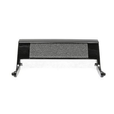
| Деталь: | Площадка отделения бумаги из кассеты |
| Парткод: | LM4143001 |

| Деталь: | Узел захвата бумаги в узле сканирования, в сборе |
| Парткод: | LF6439002 |
| Цена: | 8 100 ₽ |

| Деталь: | Ролик отделения бумаги в узле сканирования |
| Парткод: | UF5511001 |
| Цена: | 700 ₽ |
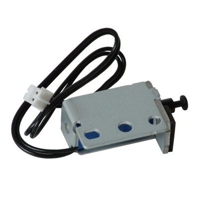
| Деталь: | Соленоид |
| Парткод: | LM4238001 |

| Деталь: | Соленоид |
| Парткод: | LM4234001 |

| Деталь: | Винт |
| Парткод: | 087320616 |

| Деталь: | Fax PCA (M477 |
| Парткод: | LG6382001 |
| Цена: | 750 ₽ |

| Деталь: | Телефонная трубка (цвет: серый) |
| Парткод: | LF1518016 |
| Цена: | 1 500 ₽ |

| Деталь: | Лоток выхода бумаги из узла автоматической подачи |
| Парткод: | LF6496002 |
| Цена: | 1 300 ₽ |

| Деталь: | Блок лазера |
| Парткод: | LM4578001 |
| Цена: | 15 800 ₽ |
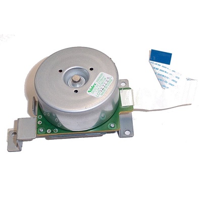
| Деталь: | Главный мотор |
| Парткод: | LM4341001 |
| Цена: | 2 800 ₽ |
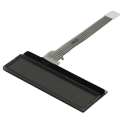
| Деталь: | Дисплей |
| Парткод: | LG6059001 |

| Деталь: | Плата датчика наличия тонера |
| Парткод: | LJ9740001 |

| Деталь: | Датчик крышки доступа к картриджам |
| Парткод: | LG5845001 |

| Деталь: | Датчик сброса тонер-картриджа |
| Парткод: | LG5832001 |

| Деталь: | Термистор |
| Парткод: | LG5834001 |

| Деталь: | Плата датчика наличия тонера |
| Парткод: | LJ9747001 |

| Деталь: | Fax PCA (M477 |
| Парткод: | LG6382001 |
| Цена: | 750 ₽ |

| Деталь: | Телефонная трубка (цвет: серый) |
| Парткод: | LF1518016 |
| Цена: | 1 500 ₽ |

| Деталь: | Лоток выхода бумаги из узла автоматической подачи |
| Парткод: | LF6496002 |
| Цена: | 1 300 ₽ |

| Деталь: | Прижимной вал |
| Парткод: | LM4013001 |
| Цена: | 2 700 ₽ |

| Деталь: | Шестерня привода тефлонового вала |
| Парткод: | LM4010001 |
| Цена: | 250 ₽ |

| Деталь: | Термистор |
| Парткод: | LM4865001 |
| Цена: | 1 100 ₽ |

| Деталь: | Лампа нагрева тефлонового вала |
| Парткод: | LM4022001 |
| Цена: | 1 100 ₽ |

| Деталь: | Палец отделения бумаги от тефлонового вала |
| Парткод: | LM4994001 |
| Цена: | 470 ₽ |
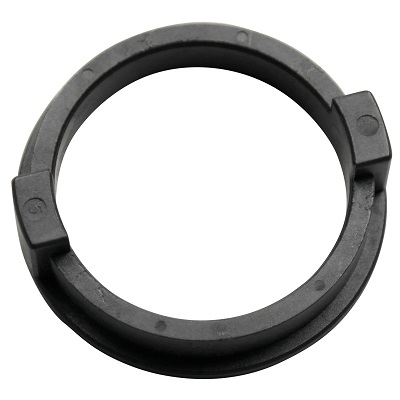
| Деталь: | Подшипник тефлонового вала |
| Парткод: | LM6735001 |
| Цена: | 440 ₽ |

| Деталь: | Подшипник тефлонового вала |
| Парткод: | LM6736001 |
| Цена: | 550 ₽ |

| Деталь: | PANEL UNIT, MFC9840CDW |
| Парткод: | LM6724001 |
| Цена: | 15 600 ₽ |
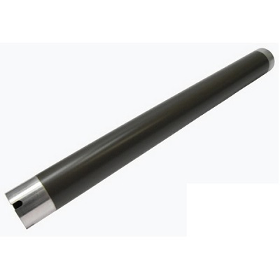
| Деталь: | Тефлоновый вал |
| Парткод: | LM4009001 |
| Цена: | 1 600 ₽ |
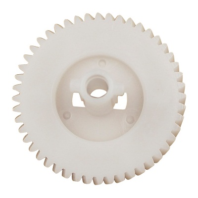
| Деталь: | Шестерня главного редуктора |
| Парткод: | LM4225001 |
| Цена: | 200 ₽ |

| Деталь: | Чистящий ролик |
| Парткод: | LJ7432001 |
| Цена: | 20 ₽ |

| Деталь: | Комплект из 4-х пластиковых роликов и пружин для узла выхода бумаги |
| Парткод: | LM6598001 |
| Цена: | 1 400 ₽ |
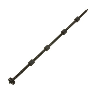
| Деталь: | Вал выхода бумаги из узла термозакрепления |
| Парткод: | LM4105001 |
| Цена: | 600 ₽ |
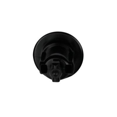
| Деталь: | Муфта шестерни главного редуктора |
| Парткод: | LM4227001 |
| Цена: | 190 ₽ |

| Деталь: | Флажок датчика сброса тонер-картриджа |
| Парткод: | LM4260001 |

| Деталь: | Пружина флажка датчика сброса тонер-картриджа |
| Парткод: | LM4261001 |

| Деталь: | Пружина |
| Парткод: | LM6480001 |

| Деталь: | Пружина соленоида |
| Парткод: | LM4633001 |

| Деталь: | Вентилятор |
| Парткод: | LF6856001 |

| Деталь: | Держатель светодиода датчика наличия тонера |
| Парткод: | LM4267001 |
Коды ошибок
56
5B
6A
6B
6C
6E
6F
71
72
73
74
75
76
77
78
79
7A
7B
80
81
Описание
| Error code: | 56 |
| Display: | Toner Empty |
| Description: | The toner cartridge has run out. The machine stops printing. |
| Causes: | Harness connection failure of back cover switch ASSY. Eject actuator failure. Eject sensor PCB ASSY failure. Main PCB failure |
| Remedy: | Replace the toner cartridge with a new one. |
| Error code: | 5B |
| Display: | Unable to print 5B |
| Description: | New toner detection lever malfunction |
| Causes: | New toner detection switch harness connection failure. New toner detection switch failure. Main PCB failure |
| Remedy: | 1 New toner detection switch harness connection failure Check the harness connection of the new toner detection switch. Then, reconnect it. 2 New toner detection switch failure Replace the new toner harness ASSY. 3 Main PCB failure Replace the main PCB ASSY. |
| Error code: | 6A |
| Description: | Fuser unit failure (The side thermistor does not detect 60°C within the specified time.) |
| Causes: | Fuser unit harness connection failure. Fuser unit failure. LVPS PCB unit failure. Main PCB failure. |
| Remedy: | 1 Fuser unit harness connection failure Check the harness connection of the fuser unit and reconnect it. 2 Fuser unit failure Replace the fuser unit. 3 LVPS PCB unit failure Replace the LVPS PCB unit. 4 Main PCB failure Replace the main PCB ASSY. |
| Error code: | 6B |
| Description: | Fuser unit failure (The center thermistor does not detect 100°C within the specified time.) |
| Causes: | Fuser unit harness connection failure. Fuser unit failure. LVPS PCB unit failure. Main PCB failure. |
| Remedy: | 1 Fuser unit harness connection failure Check the harness connection of the fuser unit and reconnect it. 2 Fuser unit failure Replace the fuser unit. 3 LVPS PCB unit failure Replace the LVPS PCB unit. 4 Main PCB failure Replace the main PCB ASSY. |
| Error code: | 6C |
| Display: | Unable to Print 6C |
| Description: | Fuser unit failure (The center thermistor detects higher temperature than the specified value.) |
| Causes: | Fuser unit harness connection failure. Fuser unit failure. LVPS PCB unit failure. Main PCB failure. |
| Remedy: | 1 Fuser unit harness connection failure Check the harness connection of the fuser unit and reconnect it. 2 Fuser unit failure Replace the fuser unit. 3 LVPS PCB unit failure Replace the LVPS PCB unit. 4 Main PCB failure Replace the main PCB ASSY. |
| Error code: | 6E |
| Description: | Fuser unit failure (The center thermistor does not detect temperature rising within the specified time.) |
| Causes: | Fuser unit harness connection failure. Fuser unit failure. LVPS PCB unit failure. Main PCB failure. |
| Remedy: | 1 Fuser unit harness connection failure Check the harness connection of the fuser unit and reconnect it. 2 Fuser unit failure Replace the fuser unit. 3 LVPS PCB unit failure Replace the LVPS PCB unit. 4 Main PCB failure Replace the main PCB ASSY. |
| Error code: | 6F |
| Display: | Unable to Print 6F |
| Description: | Fuser unit failure (The center and side thermistors detect extremely high temperature.) |
| Causes: | Fuser unit harness connection failure. Fuser unit failure. LVPS PCB unit failure. Main PCB failure. |
| Remedy: | 1 Fuser unit harness connection failure Check the harness connection of the fuser unit and reconnect it. 2 Fuser unit failure Replace the fuser unit. 3 LVPS PCB unit failure Replace the LVPS PCB unit. 4 Main PCB failure Replace the main PCB ASSY. |
| Error code: | 71 |
| Display: | Paper Jam 0 |
| Description: | Paper Jam 0 |
| Causes: | The front part of paper is jammed between pickup unit and Feed sensor. |
| Error code: | 72 |
| Display: | Paper Jam 1 |
| Description: | Engine Firmware Failure The Engine Control Board detected a firmware error. |
| Causes: | • Engine Control Board, Pl9.1.16 • EEPROM Board, PL9.1.12 |
| Remedy: | 1 Cycle printer power. Does the error persist? Go to Step 2. Complete 2 Is P/J144 on the EEPROM Board properly seated and defect free? Go to Step 3. Reseat P/J144 or replace the EEPROM Board. 3 Turn printer power off and then back on. Does the error persist? Replace the Engine Control Board. Complete |
| Error code: | 73 |
| Display: | Paper Jam 2 |
| Description: | Paper Jam 2 |
| Causes: | The front part of paper is jammed just after passing through the discharge sensor. |
| Error code: | 74 |
| Display: | [TRAY x] [PAPER SIZE] EMPTY |
| Description: | F/W Overrun detect |
| Causes: | · Loose cable connection · Defective cleaner clutch · Defective IOD2 board · Defective IOD1 board · Defective MCTL board |
| Remedy: | 1) Check the harness connected between the Engine controller and the TA board. (If the harness is out, insert it to the connector.) 2) Check the harness connected between the TA board and the Pickup unit. (If the harness is out, insert it to the connector.) 3) Check the harness connected between the Pickup unit and the cassette sensing board. (If the harness is out, insert it to the connector.) 4) Check the pickup unit. (If it is inferior part or warped part, replace it.) 5) Check the damage of the cassette sensing B . (If it is damaged, replace the cassette sensing board.) 6) In the Engine diagnostic mode, operate the running count of the paper if it is under 39. (If it is over 39, replace the Pickup unit.) 7) Replace the TA board. |
| Error code: | 75 |
| Display: | [TRAY x] NOT INSTALLED |
| Description: | VIC Limutter |
| Causes: | · Loose cable connection · Defective fusing unit clutch · Defective IOD2 board · Defective MCTL board |
| Remedy: | 1) Check for any warping or damage to the cassette (In the case of warping or damage, replace the cassette) |
| Error code: | 76 |
| Display: | Out Bin Full |
| Description: | Fuser Firmware Failure A failure was detected in the Fuser Firmware. |
| Causes: | • Fuser, PL5.1.1 • FSR/ADC Harness, PL5.2.28 • Engine Control Board, PL9.1.16 |
| Remedy: | 1 Check the Fuser for damage. Is the Fuser damaged? Replace the Fuser. Go to Step 2. 2 Check the Fuser connection for damage. Any broken or bent pins? Repair or replace the parts. Go to Step 3. 3 Replace the Fuser. Does the error persist? Go to Step 4. Complete 4 Check all pins on the FSR/ADC Harness PL5.2.28 for continuity. 1. Disconnect P/J36 and P/J361. 2. Check continuity between J36 <=> J361. Replace the Engine Control Board. Replace the FSR/ ADC Harness. |
| Error code: | 77 |
| Display: | WAIT IMAGE |
| Description: | Image Density Failure The engine detected a low-density image condition. |
| Causes: | • Transfer Roller, PL5.1.4 • CTD (ADC) Sensor PL5.2.19 • Engine Control Board PL9.1.16 • FSR/ADC Harness PL5.2.28 |
| Remedy: | 1 Clean the CTD (ADC) Sensor. Does the error persist? Go to Step 2. Complete 2 Check the following for evidence of fault or damage: Transfer Roller Assembly, PL5.1.4 CTD (ADC) Sensor, PL5.2.19 Replace any damaged parts. Go to Step 3. 3 Check the CTD (ADC) Sensor connector. Is P/J136 connected to the harness? Go to Step 4. Reseat the connector to the sensor. 4 Replace the CTD (ADC) Sensor. Does the error persist? Go to Step 5. Complete 5 Check all pins on the FSR/ADC Harness PL5.2.28 for continuity. 1. Disconnect P/J36 and P/J136 2. Check continuity between J36 <=> J136 Replace the Engine Control Board Replace the FSR/ ADC Harness. |
| Error code: | 78 |
| Display: | WRONG PAPER SIZE [PAPER] IN [TRAY x] |
| Description: | Waste Cartridge Full Detection Sensor Failure, Code 78 |
| Causes: | • Waste Cartridge • Waste Cartridge Full Sensor • Engine Control Board |
| Remedy: | 1 1. Remove the waste cartridge sensor holder without disconnecting the harnesses. 2. Measure the voltage between the yellow wire on the waste cartridge full sensor and frame ground, alternately interrupting the sensor. 3. Does the voltage toggle between +5 and 0 VDC? Go to step 5. Go to step 2. 2 1. Measure the voltage between the gray wire and frame ground. 2. Does the voltage measure +5 VDC? Go to step 4. Go to step 3. 3 1. Remove the rear cover and rear shield. 2. Measure the voltage at J407B-17 on the engine control board. 3. Does the voltage measure +5 VDC? Inspect the wiring harness for damage and replace, if necessary. Replace the engine control board. 4 1. Measure the voltage between the violet wire and frame ground. 2. Does the voltage measure 0 VDC? Replace the waste cartridge full sensor. Inspect the wiring harness for damage and replace, if necessary. 5 1. Remove the rear cover and rear shield. 2. Measure the voltage at J407B-16 on the engine control board. 3. Alternately interrupt the sensor 4. Does the voltage toggle between +5 and 0 VDC? Replace the engine control board. Inspect the wiring harness for damage and replace, if necessary. |
| Error code: | 79 |
| Display: | 79 |
| Description: | No detection of the internal temperature thermistor. |
| Causes: | Harness connection failure of internal temperature thermistor. Internal temperature thermistor failure. Main PCB failure |
| Remedy: | 1 Harness connection failure of internal temperature thermistor Check the harness connection of the internal temperature thermistor, and reconnect it. 2 Internal temperature thermistor failure Replace the internal temperature thermistor. 3 Main PCB failure Replace the main PCB ASSY. |
| Error code: | 7A |
| Display: | Unable to clean 7A |
| Description: | No detection of the main motor lock signal. |
| Causes: | Main motor failure. Main PCB failure. |
| Remedy: | 1 Main motor failure Replace the main motor ASSY. 2 Main PCB failure Replace the main PCB ASSY. |
| Error code: | 7B |
| Display: | Unable to clean 7B |
| Description: | Main PCB failure |
| Causes: | Main PCB failure |
| Remedy: | 1 Main PCB failure Replace the main PCB ASSY. |
| Error code: | 80 |
| Display: | ERROR 80 FORMAT |
| Description: | Engine Logic Board Failure, Code 80 |
| Remedy: | 1. Cycle power to the printer to clear the error. 2. Did this clear the error? Complete Replace the engine control board or the image processor board. |
| Error code: | 81 |
| Display: | 81 |
| Description: | Controller to Engine Communications Failure, Code 81 |
| Remedy: | 1. Cycle power to the printer to clear the error. 2. Turn the printer off. 3. Remove the Image processor board, IP board cover and metal cover. 4. Inspect the orange ribbon cable between the relay board and the engine control board. 5. Is the connector fully seated and free from damage? Replace in the following order: • Image processor board • Electrical chassis assembly • Engine control board |
