
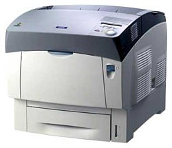
Epson AcuLaser C3000
Рейтинг
Снят с производства
Тип устройства
Принтер
Технология печати
лазерная
Макс. формат
A4
Число страниц в месяц
60000
Скорость печати
A4
24
Цветность печати
цветная
Общие характеристики |
|
---|---|
Технология печати |
лазерная |
Тип |
лазерный/светодиодный |
Область применения |
средний офис |
Число страниц в месяц |
60 000 |
Тип устройства |
Принтер |
Цветность печати |
цветная |
Макс. формат |
A4 |
Копир |
|
Печать фотографий |
|
Сканер |
|
Принтер |
|
Количество цветов |
4 |
Двусторонняя печать |
![]() |
Прямая печать |
|
Макс, разрешение для ч/б печати |
|
По X | 600 |
По Y | 600 |
Скорость ч/б печати |
|
A4 | 24 |
Расходные материалы |
|
Ресурс ч/б картриджа/тонера |
4 500 |
Ресурс цветного картриджа/тонера |
3 500 |
Печать на: |
|
Фотобумаге |
![]() |
Пленках |
![]() |
Этикетках |
![]() |
Подача бумаги |
|
Стандартная | 600 |
Интерфейсы |
|
USB |
![]() |
Инфракрасный порт |
|
LPT |
|
Ethernet (RJ-45) |
|
Память/Процессор |
|
Объем памяти |
64 |
Макс, объем памяти |
576 |
Дополнительная информация |
|
Мин. системные требования |
![]() |
Поддержка ОС |
|
Windows |
![]() |
Mac OS |
![]() |
DOS |
|
Linux |
|
Уровень шума |
|
При работе | 55 |
Габариты |
|
Высота |
445 |
Вес |
36 |
Ширина |
439 |
Глубина |
638 |
Модули
MECH-019 (15.1)
MECH-004 (04.01)
ELEC-001 (16.1)
MECH-008 (06.1)
MECH-007 (05.1)
MECH-005 (04.02)
MECH-017 (13.1)
MECH-013 (11.1)
CASE-001 (01.1)
MECH-015 (12.2)
MECH-002 (03.1)
MECH-020 (15.2)
MECH-016 (12.3)
MECH-012 (10.1)
MECH-009 (07.1)
MECH-006 (04.3)
MECH-011 (09.1)
MECH-010 (08.1)
MECH-014 (12.1)
MECH-001 (02.1)
MECH-018 (14.1)
Детали CASE-001 (01.1)
Деталь: | PWBA MCU CPU HBN STD |
Парткод: | 2089815 |
Деталь: | FAN REAR |
Парткод: | 2071870 |
Деталь: | CLAMP GUIDE HARNESS |
Парткод: | 2071871 |
Деталь: | LVPS |
Парткод: | 2087623 |
Деталь: | HARNESS ASSY AC SW |
Парткод: | 2071874 |
Деталь: | PWBA DRV HBN |
Парткод: | 2085228 |
Деталь: | COVER FDR FRONT |
Парткод: | 1110105 |
Деталь: | COVER CASSETTE REAR |
Парткод: | 1265600 |
Деталь: | BLOCK |
Парткод: | 1110107 |
Деталь: | CHUTE ASSY TURN |
Парткод: | 1110108 |
Деталь: | GUIDE L ESS |
Парткод: | 1112466 |
Деталь: | GUIDE R ESS |
Парткод: | 1112467 |
Деталь: | BOARD ASSY,MAIN |
Парткод: | 2089853 |
Деталь: | BOARD ASSY.,MEMORY |
Парткод: | 2088339 |
Деталь: | CHUTE ASSY IN |
Парткод: | 2085201 |
Деталь: | WIRE ASSY BTR 2 |
Парткод: | 2072702 |
Деталь: | WIRE ASSY DTSK |
Парткод: | 2072703 |
Деталь: | HARNESS ASSY FSR3C |
Парткод: | 2085203 |
Деталь: | HARNESS ASSY CTD |
Парткод: | 2072706 |
Деталь: | SENSOR ASSY ADC |
Парткод: | 2072707 |
Деталь: | WASTE TONER SENSOR |
Парткод: | 2028242 |
Деталь: | HARNESS ASSY TFLSNS |
Парткод: | 2072708 |
Деталь: | DRIVE ASSY FUSER |
Парткод: | 2085205 |
Деталь: | WIRE ASSY FSR EARTH |
Парткод: | 2072710 |
Деталь: | LATCH R |
Парткод: | 1111862 |
Деталь: | LATCH L |
Парткод: | 1111863 |
Деталь: | KIT ROLL PINCH TURN |
Парткод: | 1111864 |
Деталь: | KIT ROLL PINCH DUP |
Парткод: | 1111865 |
Деталь: | HOUSING ASSY RETARD |
Парткод: | 2085198 |
Деталь: | ROLL TURN |
Парткод: | 1111860 |
Деталь: | ROLL ASSY RETARD |
Парткод: | 1111861 |
Деталь: | CLUTCH TURN MSI |
Парткод: | 2085199 |
Деталь: | HOUSING FDR L |
Парткод: | 1279590 |
Деталь: | HOUSING FDR R |
Парткод: | 1279591 |
Деталь: | HARNESS ASSY TMPA |
Парткод: | 2071858 |
Деталь: | ENVIRONMENT SENSOR |
Парткод: | 2061097 |
Деталь: | FOOT |
Парткод: | 1231706 |
Деталь: | STOPPER CST |
Парткод: | 1110111 |
Деталь: | SWITCH SIZE TRAY 1 |
Парткод: | 1110112 |
Деталь: | HARNESS ASSY OPFREC |
Парткод: | 2071859 |
Деталь: | LEVER LOW PAPER |
Парткод: | 1110113 |
Деталь: | INDICATOR |
Парткод: | 1110115 |
Деталь: | BRACKET LEVER |
Парткод: | 1112454 |
Деталь: | LEVER DRUM |
Парткод: | 1112455 |
Деталь: | SPRING LEVER 30N |
Парткод: | 1112456 |
Деталь: | ACTUATOR I/L |
Парткод: | 1112457 |
Деталь: | GEAR IDL PRESS |
Парткод: | 1112459 |
Деталь: | GEAR ASSY PR R |
Парткод: | 1112460 |
Деталь: | FILM REGI |
Парткод: | 1112461 |
Деталь: | PWBA ASSY EARTH |
Парткод: | 2071868 |
Деталь: | GEAR ASSY PR L |
Парткод: | 1112462 |
Деталь: | CHASSIS MAIN |
Парткод: | 1265573 |
Деталь: | ROS ASSY |
Парткод: | 2085214 |
Деталь: | HSG ASSY BIAS |
Парткод: | 1112434 |
Деталь: | STUD PLUNGER |
Парткод: | 1112438 |
Деталь: | KIT HSG ASSY BIAS |
Парткод: | 1112431 |
Деталь: | CONTROL PANEL |
Парткод: | 2085361 |
Деталь: | COVER ASSY FRONT HEAD |
Парткод: | 2091083 |
Деталь: | COVER FRONT HEAD |
Парткод: | 1110076 |
Деталь: | FAN FUSER |
Парткод: | 2085193 |
Деталь: | CVR TOP STOPPER |
Парткод: | 1110078 |
Деталь: | COVER TOP |
Парткод: | 1110079 |
Деталь: | COVER ASSY TOP MAIN |
Парткод: | 1289192 |
Деталь: | LATCH TOP R |
Парткод: | 1110082 |
Деталь: | LATCH TOP L |
Парткод: | 1265592 |
Деталь: | COVER REAR |
Парткод: | 1110084 |
Деталь: | KIT COVER ASSY TOP |
Парткод: | 1110077 |
Деталь: | KIT COVER ASSY TOP PHD |
Парткод: | 1265593 |
Деталь: | KIT HOLDER ASSY TONER(Y) |
Парткод: | 2085216 |
Деталь: | KIT HOLDER ASSY TONER(M) |
Парткод: | 2085217 |
Деталь: | KIT HOLDER ASSY TONER(C) |
Парткод: | 2085218 |
Деталь: | KIT HOLDER ASSY TONER(K) |
Парткод: | 2085219 |
Деталь: | SENSOR TONER LOW |
Парткод: | 2085220 |
Деталь: | CHUTE RETADE |
Парткод: | 1110098 |
Деталь: | ROLL ASSY |
Парткод: | 1110099 |
Деталь: | HOLDER RETARD |
Парткод: | 1290235 |
Деталь: | SPRING RETARD |
Парткод: | 1290236 |
Деталь: | HARNESS ASSY LVNC3 |
Парткод: | 2085229 |
Деталь: | HARNESS ASSY DRV 1 |
Парткод: | 2071877 |
Деталь: | HARNESS ASSY DRV 2.2 |
Парткод: | 2086086 |
Деталь: | HARNESS ASSY LVRPG |
Парткод: | 2071879 |
Деталь: | HARNESS ASSY ROS KA2 |
Парткод: | 2085232 |
Деталь: | HARNESS ASSY 24V |
Парткод: | 2071881 |
Деталь: | HARNESS ASSY FRONT 1 |
Парткод: | 2071882 |
Деталь: | HARNESS ASSY OPF MAIN |
Парткод: | 2071883 |
Деталь: | HARNESS ASSY OPSEA |
Парткод: | 2085234 |
Деталь: | HARNESS ASSY EEPROM |
Парткод: | 2071885 |
Деталь: | HARNESS ASSY TMPNCS |
Парткод: | 2085235 |
Деталь: | PLATE ASSY DISPENSER |
Парткод: | 2085221 |
Деталь: | BOX ASSY CRUM READER |
Парткод: | 2085319 |
Деталь: | HARNESS ASSY CRUM |
Парткод: | 2071867 |
Деталь: | RACK V |
Парткод: | 1112451 |
Деталь: | GEAR SLIDE |
Парткод: | 1112452 |
Деталь: | RACK H |
Парткод: | 1112453 |
Деталь: | CHUTE ASSY REGI |
Парткод: | 2085209 |
Деталь: | CLUTCH REGI |
Парткод: | 2085210 |
Деталь: | E.R.M. SENSOR |
Парткод: | 2021773 |
Деталь: | ACTUATOR REGI |
Парткод: | 1112416 |
Деталь: | HOUSING ASSY |
Парткод: | 1112417 |
Деталь: | HARNESS ASSY FRONT 2 |
Парткод: | 2071861 |
Деталь: | HARNESS ASSY OPEPANE BS |
Парткод: | 2071862 |
Деталь: | E.R.M. SENSOR |
Парткод: | 2021773 |
Деталь: | ACTUATOR FULL STACK |
Парткод: | 1111867 |
Деталь: | ROLL DUP |
Парткод: | 1111866 |
Деталь: | ACTUATOR DUP |
Парткод: | 1111868 |
Деталь: | HARNESS ASSY DUP 2 |
Парткод: | 2085207 |
Деталь: | ROLL ASSY FEED |
Парткод: | 1111869 |
Деталь: | ACTUATOR MSI |
Парткод: | 1111870 |
Деталь: | SOLENOID FEED MSI |
Парткод: | 1111871 |
Деталь: | WIRE ASSY DUP EARTH |
Парткод: | 2072713 |
Деталь: | KIT ROLL PINCH EXIT |
Парткод: | 1265606 |
Деталь: | KIT ROLL PINCH |
Парткод: | 1265607 |
Деталь: | PICK UP ASSY |
Парткод: | 2071887 |
Деталь: | ROLL ASSY FEED |
Парткод: | 1110119 |
Деталь: | EXIT SENSOR |
Парткод: | 2026720 |
Деталь: | ACTUATOR LINK |
Парткод: | 1021488 |
Деталь: | SOLENOID FEED TRAY 1 |
Парткод: | 2071888 |
Деталь: | CLUTCH ASSY TURN TRAY 1 |
Парткод: | 1110121 |
Деталь: | ROLL ASSY TURN |
Парткод: | 1110122 |
Деталь: | ROLL ASSY |
Парткод: | 1110099 |
Деталь: | HARNESS ASSY FEEDER |
Парткод: | 2071860 |
Деталь: | FUSER ASSY (220V) |
Парткод: | 2085468 |
Деталь: | CHUTE ASSY EXIT |
Парткод: | 1265628 |
Деталь: | ROLL EXIT |
Парткод: | 1111876 |
Деталь: | ROLL MID |
Парткод: | 1111877 |
Деталь: | MOTOR ASSY DUP |
Парткод: | 2085398 |
Деталь: | KIT GLOMET |
Парткод: | 1267092 |
Деталь: | HRANESS ASSY TNR4SE |
Парткод: | 2085215 |
Деталь: | PWB EEPROM |
Парткод: | 2071865 |
Деталь: | HVPS SUB |
Парткод: | 2071866 |
Деталь: | STRAP |
Парткод: | 1110097 |
Коды ошибок
0017 ... 0800
0998, 0999
100
1002
101
1010
102
1020, 1021
103
104
105
106
107
1100, 1101
1120 ... 1123
1180, 1185
1200, 1210
1400
1500
1550
1600
1700
1800
1999
2000
998
Описание
Error code: | 0017 ... 0800 |
Description: | 0017 CPU error (Interrupt exception) 0088 CPU error (System call exception) 0089 CPU error (Break point exception) 0091 CPU error (Disabled floating-point exception) 0300 CPU error (Reserved (undefined) exception) 0301 CPU error (Machine check exception) 0302 CPU error (Data access exception) 0303 CPU error (Instruction access exception) 0304 CPU error (Alignment exception) 0305 CPU error (Program exception) 0306 CPU error (Trace exception) 0307 CPU error (Performance monitor exception) 0308 CPU error (System administration interrupt exception) 0309 CPU error (Temperature management interrupt exception) 0800 IPL error (Controller defective) |
Remedy: | 1 Initial setting: • Remove all the optional units and modules related to the electrical system and bring the printer back to the standard status. • Check if all connectors are properly connected to the CONTROLLER PWB. • Reinsert the DIMM. Replace or reinstall the relevant part. Go to step 2. 2 Improving the CONTROLLER PWB Environment: • Update the program to the latest one in the DIMM.ÅB Replace or reinstall the relevant part. Go to step 3. 3 Replacing the CONTROLLER PWB and Performing Checks: Does the problem still occur after replacing the MCU PWB with a normal one? - Problem solved. |
Error code: | 0998, 0999 |
Description: | 0998 Engine communication error (Only when powering on) 0999 No Engine Flash ROM program data |
Remedy: | 1 Turn off the power and turn on the power. Does the problem occur? Go to step 2. Problem solved, or if an error occurs again, go to step 2. 2 PWBA MCU & HVPS 1. Replace the PWBA MCU & HVPS with a new part. (Refer to Ch4-4.2.18.1) 2. Turn On the power. Does the problem still occur? Go to FIP-Noise . Problem solved |
Error code: | 100 |
Description: | A fault has occurred |
Causes: | • ROS ASSY • PWBA MCU |
Remedy: | 1 Make sure all packing material is removed from the printer. The detensioner is located underneath the toner cartridges. Make sure the ITU Detensioner is removed. Remove the Detensioner by pulling up on the red handle on the right side of the ITU. Note: All the print cartridges must be removed to gain access to the Detensioner packing material. Has all packing material been removed from the printer? Go to step 2 Remove any remaining packing material from the printer 2 Check the ITU Release Lever for correct operation. The ITU Release Lever is the black lever located on the left upper side frame above the ITU opening and can be seen by opening and lowering the MPF Assembly. When locked the lever should be at the 6 o`clock position. When unlocked it should be in a 3 o`clock position. Undue pressure is not required to operate the lever. Does the ITU release lever operate correctly? Go to step 3 Repair as necessary 3 Check the second transfer roll installation. Is it installed correctly? Go to step 4 Reinstall the second transfer roll. 4 Check the display error log in the Diagnostic Menu. Is 100 ITU preceded in the log by a 104 ITU Error? Go to “104 ITU Error”. Go to step 5 5 Remove the ITU assembly and check that the sensor cable is seated in the handle of the ITU assembly correctly. Note: The sensor connector is located on the side of the ITU handle assembly. Is the cable seated correctly? Go to step 6 Reinstall the cable correctly. Check again for a 100 ITU Error. If 100 ITU Error is displayed, go to step 6 6 The front contamination shield is attached to the font plate of the ITU frame and lies on the top of the ITU belt. Is the front contamination shield lying on the belt? Go to step 7 Position the shield on top of the belt. 7 Make sure the ITU Cleaner Gear (A) is turning. Observe the gear by opening the front Paper Jam Door above the integrated paper tray 1. Observe the white cleaner gear during POR. The gear should turn slowly and smoothly for approximately 8 seconds before the printer displays a 100 ITU error. Is the ITU Cleaner Gear turning? Go to step 11 Go to step 8 8 Check to see if the ITU Drive Roll Gear (A) is turning during POR. Observe the gear by opening the MFP door to its horizontal position. Observe the gear on the left end of the ITU Drive Roll. The ITU Drive Roll Gear should turn for a few seconds slowly and smoothly before the printer posts a 100 ITU error. Does the Gear turn? Go to step 10 Go to step 9 9 Check to see if the ITU Drive Motor is turning during POR. Observe the ITU Motor during POR by removing the Rear Cover. Is the ITU Drive Motor turning? Replace the “ITU drive assembly” Go to step 10 10 Check the printer is setting on a solid flat surface. Is the printer setting on a solid flat surface? Go to step 11 Place the printer on a solid flat surface. 11 Make sure the ITU drive motor assembly cable is correctly installed to the ITU drive motor and at connector location J64 on the system board. Is the cable correctly installed? Go to step 12 Install the cable correctly 12 Make sure the ITU Autoconnect Cable is installed correctly at connector location J72 on the system board. Is the cable correctly installed? Go to step 13 Install the connector/cable correctly 13 Make sure the ITU Autoconnect connector in the printer is seated correctly in the connector plate. Is the connector seated correctly? Replace the following FRUs in the following order: 1. “ITU assembly”. 2. “System board”. Replace the ITU Autoconnect cable. |
Error code: | 1002 |
Description: | Standard RAM error (When the standard size is not determined, etc.) |
Remedy: | 1 • Initial setting: • Remove all the optional units and modules related to the electrical system and bring the printer back to the standard status. • Check if all connectors are properly connected to the CONTROLLER PWB. Replace or reinstall the relevant part. Go to step 2 2 • Checking the SD-RAM: • Remove all SD-RAMs from the RAM slots and then reinsert them in the RAM slots. Be sure to insert the SD-RAMs one by one (S0 and S1) in order so that the SD-RAM error can be identified. Every time you insert an SD-RAM, follow the procedures below and repeat it for each one. 1 Turn the power off. 2 Add the SD-RAM 3 Turn the power on. • Insert the SD-RAM in the socket until it is locked securely. NOTE: Since the SD-RAM has the right direction to insert, be sure to insert it in the correct direction. Replace or reinstall the relevant part. Problem solved |
Error code: | 101 |
Description: | Replace Maintenance Kit The Printer detected an error condition that indicates the parts listed below need to be replaced. This will ensure the rated engine life of 600,000 prints is achievable. |
Causes: | • Long-Life Maintenance Kit, 650-4360-00 |
Remedy: | 1 Follow the procedure starting and replace all concerned parts. Have all parts outlined in the procedure been replaced? Go to the Hidden Service menu on the Control Panel and Reset the Maintenance Kit Life count. Replace all concerned parts. |
Error code: | 1010 |
Display: | Problem with Printhead L/R Chk printing results |
Description: | Lift motor 1 error After cassette 1 is inserted, lift sensor 1 does not turn on within 12 s. This error is detected 4 times successively. The lock signal of the motor is detected continuously for 1 s. This error is detected 4 times successively. |
Causes: | Defective bottom plate elevation mechanism in the cassette. Defective connector cable or poor contact in the connector. Defective drive transmission system of motor. Defective lift motor 1. Defective engine PWB. |
Remedy: | Cassette lift base elevating mechanism Check that the cassette base can be manipulated smoothly, if not, repair or replace. Lift motor 1 1. Check that the cassette base has been ascended. 2. Check the drive gear can rotate or they are not unusually loaded and, if necessary, replace. 3. Confirm that the wiring connector is firmly connected and, if necessary, connect the connector all the way in. Lift motor 1 and Feed PWB 2 (YC3) Feed PWB 2 (YC1) and Engine PWB (YC4) 4. If the wiring is disconnected, shorted or grounded, replace the wiring. 5. Replace the lift motor 1. Lift sensor 1 1. Check that the sensor is correctly positioned. 2. Confirm that the wiring connector is firmly connected and, if necessary, connect the connector all the way in. Lift sensor 1 and Feed PWB 2 (YC8) Feed PWB 2 (YC1) and Engine PWB (YC4) 3. If the wiring is disconnected, shorted or grounded, replace the wiring. 4. Replace the lift sensor1. Feed PWB 2 Replace the Feed PWB 2. Engine PWB 1. Check the engine software and upgrade to the latest, if necessary. 2. Replace the engine PWB. |
Error code: | 102 |
Display: | Service Call 102: Error |
Description: | Environmental Sensor Failure An error was detected in the Environmental Sensor circuitry. |
Causes: | • Temp/Humidity Sensor, PL9.1.20 • TMP Harness, PL10.1.4 |
Remedy: | 1 Test the Temperature/Humidity Sensor. Run the Service Diagnostics Temperature/ Humidity Sensor test. Does the sensor function correctly? Go to Step 2. Replace the Temp/ Hum Sensor. 2 Check the Humidity signal. Disconnect P/J231. Is the voltage across P/J231-2 <=> P/J231-3 less than +3 V and above +0.5 V. Go to Step 4. Go to Step 3. 3 Check the Temperature signal. Disconnect P/J231. Is the voltage across P/J231-4 <=> P/J231-3 greater than +2.5 V? Go to Step 4. Replace the Engine Control Board. 4 Check for +5 V to the Temperature/ Humidity Sensor. Disconnect P/J231. Is there +5 V across P/J231-1 <=> P/J231-3? Replace the Temp/ Hum Sensor. Replace the Engine Control Board. |
Error code: | 1020, 1021 |
Description: | 1020 RAM error (Slot 0) 1021 RAM error (Slot 1) |
Remedy: | 1 • Initial setting: • Remove all the optional units and modules related to the electrical system and bring the printer back to the standard status. • Check if all connectors are properly connected to the CONTROLLER PWB. Replace or reinstall the relevant part. Go to step 2 2 • Checking the SD-RAM: • Remove all SD-RAMs from the RAM slots and then reinsert them in the RAM slots. Be sure to insert the SD-RAMs one by one (S0 and S1) in order so that the SD-RAM error can be identified. Every time you insert an SD-RAM, follow the procedures below and repeat it for each one. 1 Turn the power off. 2 Add the SD-RAM 3 Turn the power on. • Insert the SD-RAM in the socket until it is locked securely. NOTE: Since the SD-RAM has the right direction to insert, be sure to insert it in the correct direction. Replace or reinstall the relevant part. Problem solved |
Error code: | 103 |
Display: | Service Call 103: Error |
Description: | Fuser Motor Failure The Fuser Motor rotation signal indicates that the motor is no longer operational. |
Causes: | • Fuser Drive Assembly, PL5.2.25 • TNRFULL/FSR Harness, PL5.2.30 • Engine Control Board, PL9.1.16 • Interlock Switch, PL9.1.1 |
Remedy: | 1 Check the Fuser Drive Assembly for damage. Are any parts of the Fuser Drive Assembly damaged or excessively worn? Replace the Fuser Drive Assembly. Go to Step 2. 2 Check the Fuser Motor connection. Is P/J521 connected to the harness? Go to Step 3. Reconnect the Fuser Motor. 3 Test the Fuser Motor. 1. Close the Interlock Switch while testing. 2. Run the Service Diagnostics Fuser Motor test. Does the motor operate? Go to Step 5. Go to Step 4. 4 Check for +24 V to the Fuser Motor. Is the +24 V across P/J521-10 <=> P/J 521-8? Go to Step 6. Go to Step 5. 5 Test the Interlock Switch. Run the Service Diagnostics Interlock Switch test. Does the switch function correctly? Go to Step 6. Replace the Interlock Switch. 6 Check all pins on the TNRFULL/FSR Harness PL5.2.30 for continuity. 1. Disconnect P/J52 and P/J521. 2. Check continuity between J52 <=> J521. Replace the Engine Control Board. Replace the FSR/ ADC Harness. |
Error code: | 104 |
Display: | Service Call 104: Error |
Description: | Developer Motor Failure The Developer Motor rotation signal indicates that the motor is no longer operational. |
Causes: | • Developer Drive Assembly, PL8.1.1 • Engine Control Board, PL9.1.16 • Interlock Switch, PL9.1.11 • FAN/PHD/MOT Harness, PL10.1.9 |
Remedy: | 1 Check the Developer Drive Assembly for damage. Are any parts of the Developer Drive Assembly damaged or excessively worn? Replace the Developer Drive Assy. Go to Step 2. 2 Check the Developer Motor connection. Is P/J491 connected to the harness? Go to Step 3. Reconnect the Developer Motor. 3 Test the Developer Motor. 1. Close the Interlock Switch while testing. 2. Run the Service Diagnostics Developer Motor test. Does the motor operate? Go to Step 5. Go to Step 4. 4 Check for +24 V to the Developer Motor. Is the +24 V across P/J491-1 <=> P/J 481-5? Go to Step 6. Go to Step 5. 5 Test the Interlock Switch. Run the Service Diagnostics Interlock Switch test. Does the switch function correctly? Go to Step 6. Replace the Interlock Switch. 6 Check all pins on the FAN/PHD/MOT Harness PL10.1.9 for continuity. 1. Disconnect P/J48 and P/J491. 2. Check continuity between J48 <=> J491. Replace the Engine Control Board. Replace the FAN/PHD/MOT Harness. |
Error code: | 105 |
Display: | Service Call 105: Error |
Description: | Main Motor Failure The Main Motor rotation signal indicates that the motor is no longer operational. |
Causes: | • Main Drive Assembly, PL8.1.2 • Engine Control Board, PL9.1.16 • FAN/PHD/MOT Harness, PL10.1.9 |
Remedy: | 1 Check the Main Drive Assembly for damage. Are any parts damaged? Replace the Main Drive Assembly. Go to Step 2. 2 Check the Main Motor connection. Is P/J481 connected to the harness? Go to Step 3. Reconnect the Main Motor. 3 Test the Main Motor. 1. Close the Interlock Switch while testing. 2. Run the Service Diagnostics Main Motor test. Does the motor operate? Go to Step 5. Go to Step 4. 4 Check for +24 V to the Main Motor. Is there +24 V across P/J481-10 <=> P/J 481-8? Go to Step 6. Go to Step 5. 5 Test the Interlock Switch. Run the Service Diagnostics Interlock Switch test. Does the switch function correctly? Go to Step 6. Replace the Interlock Switch. 6 Check all pins on the FAN/PHD/MOT Harness, PL10.1.9 for continuity. 1. Disconnect P/J48 and P/J481. 2. Check continuity between J48 <=> J481. Replace the Engine Control Board. Replace the FAN/PHD/MOT Harness. |
Error code: | 106 |
Display: | Service Call 106: Error |
Description: | Motor Failure One of the primary drive motors has failed. |
Causes: | • Main Drive Assembly, PL8.1.2 • Developer Drive Assembly, PL8.1.1 • Fuser Drive Assembly, PL5.2.25 • Engine Control Board, PL9.1.16 • Interlock Switch, PL9.1.11 |
Remedy: | 1 Check the motors. Run the Service Diagnostics motor tests to determine the failed part. Is the failed part the Main Drive Motor? Go to. Test the Fuser Motor. 2 Is the failed part the Fuser Drive Motor? Go to. Test the Developer Motor. 3 Is the failed part the Developer Drive Motor? Go to. Replace the Engine Control Board. |
Error code: | 107 |
Display: | Service Call 107: Error |
Description: | Printhead Error |
Causes: | Does error reoccur? Is error recovered by reloading PU F/W? |
Remedy: | Magenta printhead lost Hsync Check for the correct installation of all the cables to the system board assembly and to the printhead assembly; J11 and J12 on the system board. Go to “System board”. If the cables are connected correctly to the system board and to the printhead assembly, go to “Printhead diagnostics”. |
Error code: | 1100, 1101 |
Description: | 1100 ROM checksum error (bit 0 ~ 15) (Font) 1101 ROM checksum error (bit 16 ~ 31) (Font) |
Remedy: | 1 • Initial setting: • Remove all the optional units and modules related to the electrical system and bring the printer back to the standard status. • Check if all connectors are properly connected to the CONTROLLER PWB. Replace or reinstall the relevant part. Go to step 2 2 • Replace the CODE ROM (C309PROG). • Replace the mounted CODE ROM with another one for checking. Replace the CONTROLLER PWB. Go to step 3 3 • Replace the IC concerned. • “Error C1100” ...Replace IC1 (M160B76JA) • “Error C1101”..Replace.IC2(M160B77JA) Replace or reinstall the relevant part. Problem solved |
Error code: | 1120 ... 1123 |
Description: | 1120 ROM checksum error (bit 0 ~ 7) 1121 ROM checksum error (bit 8 ~ 15) 1122 ROM checksum error (bit 16 ~ 23) 1123 ROM checksum error (bit 24 ~ 31) |
Remedy: | 1 • Initial setting: • Remove all the optional units and modules related to the electrical system and bring the printer back to the standard status. • Check if all connectors are properly connected to the CONTROLLER PWB. Replace or reinstall the relevant part. Go to step 2 2 • CODE ROM(C309PROG)ÇÃåšä² • Replace the mounted CODE ROM with another one for checking. Replace the CONTROLLER PWB. Go to step 3 3 • Clearing/updating the Program: • Clear the installed DIMM forcibly and update the program to the latest one in the DIMM. • Clear the new DIMM forcibly and update the program in the DIMM. Replace or reinstall the relevant part. Problem solved |
Error code: | 1180, 1185 |
Description: | 1185 Unsupported ROM module 1200 EEPROM write error |
Remedy: | 1 Initial setting: • Remove all the optional units and modules related to the electrical system and bring the printer back to the standard status. • Check if all connectors are properly connected to the CONTROLLER PWB. Replace or reinstall the relevant part. Go to step 2. 2 Checking the DIMM: • Insert the DIMM in the socket until it is locked securely. NOTE: Since the DIMM has the right direction and location for insertion, be sure to insert it in the correct direction and location. • Check if the DIMM is available for this printer, AcuLaser C4000. In cases other than above, replace the CONTROLLER PWB. Replace or reinstall the relevant part. Problem solved. |
Error code: | 1200, 1210 |
Description: | 1200 EEPROM write error 1210 EEPROM write count limit |
Remedy: | 1 • Initial setting: • Remove all the optional units and modules related to the electrical system and bring the printer back to the standard status. • Check if all connectors are properly connected to the CONTROLLER PWB. Replace or reinstall the relevant part. Go to step 2 2 • Checking the EEPROM: • “Error C1200”... Execute “SelecType Init” in the Panel Setting, or replace EEPROM. • “Error C1210”...Replace EEPROM. In cases other than above, replace the CONTROLLER PWB. Replace or reinstall the relevant part. Problem solved |
Error code: | 1400 |
Display: | Condensation Leave switched ON. Fully open the Front Cover. Wait 30 minutes, switch OFF and close cover, then switch ON. |
Description: | Rotary guide motor error The guide sensor is not detected to be on at the home position detection with the rotary guide for three times in a row. |
Causes: | Defective connector cable or poor contact in the connector. Defective drive transmission system of motor. Defective BR guide motor. Defective BR main PWB. Defective engine PWB. |
Remedy: | Rotary guide motor 1. Check the rotary guide and drive gear can rotate or they are not unusually loaded and, if necessary, replace. 2. Confirm that the wiring connector is firmly connected and, if necessary, connect the connector all the way in. Rotary guide motor and BR PWB (YC5) 3. If the wiring is disconnected, shorted or grounded, replace the wiring. 4. Replace the rotary guide motor. BR PWB Replace the BR PWB. |
Error code: | 1500 |
Display: | Print Unable 15 Turn the power off and then back on again. |
Description: | PF heater 1 high temperature error (paper feeder 1) A temperature higher than 75C/167F is detected. |
Causes: | Defective connector cable or poor contact in the connector. Shorted PF thermistor 1. Defective PF fan motor 1. Defective PF main PWB. |
Remedy: | Defective connector cable or poor contact in the connector. Reinsert the connector. Also check for continuity within the connector cable. If none, replace the cable. PF fan motor 1 and PF main PWB (YC111) Shorted PF thermistor 1. Replace the top heater unit (Refer to the service manual for the paper feeder). Defective PF fan motor 1. Replace the top heater unit (Refer to the service manual for the paper feeder). Defective PF main PWB. Replace the PF main PWB (Refer to the service manual for the paper feeder). |
Error code: | 1550 |
Description: | PF heater 2 high temperature error (paper feeder 3) A temperature higher than 75C/167F is detected. |
Causes: | Defective connector cable or poor contact in the connector. Shorted PF thermistor 2. Defective PF fan motor 2. Defective PF main PWB. |
Remedy: | Defective connector cable or poor contact in the connector. Reinsert the connector. Also check for continuity within the connector cable. If none, replace the cable. PF fan motor 2 and PF main PWB (YC111) Shorted PF thermistor 2. Replace the side heater unit (Refer to the service manual for the paper feeder). Defective PF fan motor 2. Replace the side heater unit (Refer to the service manual for the paper feeder). Defective PF main PWB. Replace the PF main PWB (Refer to the service manual for the paper feeder). |
Error code: | 1600 |
Description: | PF heater 1 low temperature error (paper feeder 1) An external temperature higher than + 5C/+ 9F is not detected when one minute elapses after PF heater 1 is turned on. |
Causes: | Defective connector cable or poor contact in the connector. PF thermistor 1 installed incorrectly. Defective PF thermistor 1. Broken PF heater 1. Defective PF heater PWB or PF main PWB. |
Remedy: | Defective connector cable or poor contact in the connector. Reinsert the connector. Also check for continuity within the connector cable. If none, replace the cable. PF heater 1 and PF heater PWB (YC1) PF heater PWB (YC3) and PF main PWB (YC113) PF thermistor 1 and PF main PWB (YC114) PF thermistor 1 installed incorrectly. Check the installation of the PF thermistor 1. Defective PF thermistor 1. Replace the top heater unit (Refer to the service manual for the paper feeder). Broken PF heater 1. Replace the top heater unit (Refer to the service manual for the paper feeder). Defective PF heater PWB or PF main PWB. Replace the PF heater PWB or PF main PWB (Refer to the service manual for the paper feeder). |
Error code: | 1700 |
Description: | Servo Motor Error The Paper-Axis or the Scan-Axis Motor moves the Carriage, but the input from the Linear Encoder Sensor does not change. |
Remedy: | • Make sure that there is no paper jam blocking the Carriage path. • Make sure that the corresponding cables are connected correctly to Connectors CN14 and CN17 on the Main PCA. • Make sure that the Linear Encoder Sensor Cable is connected correctly to the Carriage PCA. • Make sure that the Encoder Strip is not damaged or scratched. • Make sure that the pinchwheels rotate correctly. • Make sure that the Carriage gears work correctly • Replace the Main PCA. • If the error continues, replace the Paper-Axis or Scan-Axis Motors. |
Error code: | 1800 |
Description: | Paper feeder communication error A communication error from paper feeder is detected 10 times in succession. |
Causes: | Improper installation paper feeder. Defective connector cable or poor contact in the connector. Defective engine PWB. Defective PF main PWB. |
Remedy: | Paper feeder Check the wiring connection status with the main unit and, if necessary, try connecting it again. PF main PWB 1. Confirm that the wiring connector is firmly connected and, if necessary, connect the connector all the way in. PF main PWB (YC13) and Engine PWB (YC19) 2. If the wiring is disconnected, shorted or grounded, replace the wiring. 3. Replace the PF main PWB (Refer to the service manual for the paper feeder). Engine PWB 1. Check the engine software and upgrade to the latest, if necessary. 2. Replace the engine PWB. |
Error code: | 1999 |
Description: | Other hardware error |
Remedy: | 1 • Initial setting: • Remove all the optional units and modules related to the electrical system and bring the printer back to the standard status. • Check if all connectors are properly connected to the CONTROLLER PWB. Replace or reinstall the relevant part. Go to step 2 2 • Initializing the MCU PWB: • By using the DIAG command, execute “Slave Initialize”. Turn the power off once and on again. Does the printer operate normally? Problem solved Go to step 3 3 • Replacing the relevant unit: • Replace the CONTROLLER PWB. Replace or reinstall the relevant part. Problem solved |
Error code: | 2000 |
Description: | DDA Communication Error. |
Causes: | The communication error occurs when the IC4 or IC22 on the Main Board is broken. And it causes the Motor Error. |
Remedy: | Replace the Main Board. |
Error code: | 998 |
Description: | Tray Elevator Motor Error |
Causes: | • Software bug • A RAM or DIMM option needed for the application not installed, or not installed correctly • Controller board defective |
Remedy: | 1 Are the connectors CN4 at the tray elevator motor and connector PJ4 on the finisher control board properly connected? Go to step 2. Properly connect the connectors. 2 Make sure that the finisher set switch is activated. Power the printer off. Measure for approximately +24 V dc (–10%) between pins 1 and 2 of connector CN4 at the tray elevator motor. Power the printer on and observe the voltage meter during the first 12 seconds of power up. Is +24 V dc present while the printer is powering up? Replace the tray elevator motor. Go to step 3. 3 Disconnect CN4 at the tray elevator motor. Disconnect PJ4 on the finisher control board. Measure for continuity between CN4 pin 1 and PJ4 pin 7. Measure for continuity between CN4 pin 2 and PJ4 pin 8. Is there continuity in both locations? Go to step 4. Replace the cable. 4 Measure for +24 V dc (–10%) between pins 1 and 2 on connector PJ6. Is +24 V dc present? Replace the finisher control board. Replace the finisher power supply. |
Название
EPSON 0210 Тонер-картридж желтый
EPSON 0211 Тонер-картридж пурпурный
EPSON 0212 Тонер-картридж голубой
EPSON 0213 Тонер-картридж черный
EPSON Блок фотобарабана
EPSON Блок перноса изображения
EPSON Блок термозакрепления (печка)