
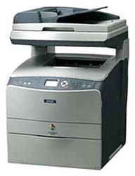
Epson AcuLaser CX21N
Рейтинг
Снят с производства
Тип устройства
МФУ
Технология печати
лазерная
Макс. формат
A4
Число страниц в месяц
45000
Скорость печати
A4
25
Цветность печати
цветная
Общие характеристики |
|
---|---|
Область применения |
малый офис |
Размещение |
настольный |
Число страниц в месяц |
45 000 |
Копир |
![]() |
Сканер |
![]() |
Тип устройства |
МФУ |
Цветность печати |
цветная |
Макс. формат |
A4 |
Факс |
|
Печать фотографий |
|
Телефон |
|
Тип |
лазерный/светодиодный |
Технология печати |
лазерная |
Принтер |
|
Время разогрева |
30 |
Печать без полей |
|
Пигментные чернила |
|
Двусторонняя печать |
|
Прямая печать |
|
Макс, разрешение для ч/б печати |
|
По Y | 600 |
По X | 2 400 |
Скорость ч/б печати |
|
A4 | 25 |
Время выхода первого отпечатка |
|
Цветн, | 29 |
Ч/б | 12 |
Копир |
|
Шаг масштабирования |
0,01 |
Макс, количество копий за цикл |
999 |
Время выхода первой копии |
29 |
Значение масштаба |
|
Максимальное | 4 |
Минимальное | 0,25 |
Макс, разрешение (ч/б) |
|
По X | 600 |
По Y | 600 |
Скорость ч/б копирования |
|
A4 | 5 |
Сканер |
|
Устройство автоподачи оригиналов |
одностороннее |
Макс. формат оригинала |
A4 |
Глубина цвета |
48 бит |
Стандарт TWAIN |
![]() |
Емкость устройства автоподачи оригиналов |
50 |
Оттенки серого |
256 |
Тип сканера |
планшетный/протяжный |
Макс, размер сканирования |
|
По X | 216 |
По Y | 297 |
Разрешение сканера |
|
По Y (улучшенное) | 9 600 |
По Х (улучшенное) | 9 600 |
По Х | 600 |
Расходные материалы |
|
Ресурс фотобарабана |
42 500 |
Ресурс цветного картриджа/тонера |
4 500 |
Ресурс ч/б картриджа/тонера |
5 000 |
Печать на: |
|
Карточках |
![]() |
Пленках |
![]() |
Этикетках |
![]() |
Глянцевой бумаге |
![]() |
Конвертах |
![]() |
Матовой бумаге |
![]() |
Рулоне |
|
Фотобумаге |
|
CD/DVD |
|
Плотность бумаги |
|
Максимальная | 210 |
Минимальная | 64 |
Факс |
|
Цветной |
|
Телефон |
|
Беспроводная трубка |
|
Стандарт DECT |
|
Спикерфон |
|
Caller ID |
|
Автоответчик |
|
Проводная трубка |
|
АОН |
|
Языки управления |
|
PostScript 3 |
![]() |
PostScript |
![]() |
PCL 6 |
![]() |
PCL 5c |
![]() |
PCL 5e |
|
PostScript 2 |
|
PPDS |
|
Лотки |
|
Подача бумаги |
|
Максимальная | 680 |
Стандартная | 180 |
Вывод бумаги |
|
Стандартный | 100 |
Финишер |
|
Сортировка со сдвигом |
|
Брошюровщик |
|
Степлер |
|
Сортер |
|
Интерфейсы |
|
Версия USB |
2,0 |
Инфракрасный порт |
|
Wi-Fi |
|
FireWire (IEEE 1394) |
|
Устройство для чтения карт памяти |
|
Bluetooth |
|
RS-232 |
|
LPT |
|
USB |
![]() |
Веб-интерфейс |
![]() |
Ethernet (RJ-45) |
![]() |
Память/Процессор |
|
Частота процессора |
400 |
Объем памяти |
128 |
Дополнительная информация |
|
Экран |
|
Поддержка ОС |
|
Linux |
![]() |
DOS |
![]() |
Windows |
![]() |
Mac OS |
![]() |
Потребляемая мощность |
|
При работе | 790 |
В режиме ожидания | 51 |
Габариты |
|
Вес |
33,1 |
Глубина |
467 |
Ширина |
460 |
Высота |
667 |
Модули
MECH-051SCAN
MECH-081
CASE-021
MECH-041ADF
MECH-031
MECH-021ADF
MECH-071
MECH-051
MECH-011
MECH-0111
MECH-021
MECH-031ADF
MECH-041
CASE-011
MECH-091
MECH-0101
CASE-011ADF
MECH-061
MECH-011ADF
Детали MECH-011
Деталь: | IR BASE A ASSY |
Парткод: | 1405573 |
Деталь: | CORE ASSY |
Парткод: | 1405581 |
Деталь: | IR TIMING BELT |
Парткод: | 1405582 |
Деталь: | IR SHAFT |
Парткод: | 1405583 |
Деталь: | PLATE HW |
Парткод: | 1405584 |
Деталь: | SPONGE1 |
Парткод: | 1405586 |
Деталь: | SPONGE3 |
Парткод: | 1405587 |
Деталь: | PLATE HARNESS |
Парткод: | 1405588 |
Деталь: | ASSLUG ASSY GND |
Парткод: | 2102560 |
Деталь: | ASSLUG ASSY GND 2 |
Парткод: | 2102561 |
Деталь: | PULLEY ASSY |
Парткод: | 1405589 |
Деталь: | MOTOR ASSY |
Парткод: | 2102562 |
Деталь: | CCD MODULE ASSY, B |
Парткод: | 1428454 |
Деталь: | IR COVER A ASSY |
Парткод: | 1405594 |
Деталь: | FFC CLIP |
Парткод: | 1405596 |
Деталь: | FERRITE BEAD |
Парткод: | 1405597 |
Деталь: | LOCK CR |
Парткод: | 1405599 |
Деталь: | FFC BOARD |
Парткод: | 2102566 |
Деталь: | PLATE HARNESS 2 |
Парткод: | 1405600 |
Деталь: | PCB ASSY |
Парткод: | 2102567 |
Деталь: | SCANNER UNIT,ADF |
Парткод: | 2091233 |
Деталь: | LABEL,FORGET PREVENTION |
Парткод: | 1405164 |
Деталь: | SHEET HOLE |
Парткод: | 1405579 |
Деталь: | LATCH ASSY-ROTARY |
Парткод: | 1432569 |
Деталь: | LEVER LATCH |
Парткод: | 1294189 |
Деталь: | ANTENNA ASSY-CTRG |
Парткод: | 1292987 |
Деталь: | LEVER CTRG SET |
Парткод: | 1294190 |
Деталь: | HOLDER ASSY-BIAS |
Парткод: | 1294191 |
Деталь: | SENSOR UPPER PASS |
Парткод: | 2091186 |
Деталь: | WIRE ASSY DEVE |
Парткод: | 2090703 |
Деталь: | HOUSING ASSY-DEVE K |
Парткод: | 1292991 |
Деталь: | HOUSING ASSY-DEVE Y |
Парткод: | 1292994 |
Деталь: | HOUSING ASSY-DEVE M |
Парткод: | 1292996 |
Деталь: | HOUSING ASSY-DEVE C |
Парткод: | 1292999 |
Деталь: | FRAME ASSY-ROTARY |
Парткод: | 1294194 |
Деталь: | PIVOT ASSY |
Парткод: | 1294195 |
Деталь: | PIVOT AD |
Парткод: | 1294196 |
Деталь: | BEARING BALL |
Парткод: | 1294197 |
Деталь: | TRAY EXTENSION |
Парткод: | 1294074 |
Деталь: | COVER TOP |
Парткод: | 1404936 |
Деталь: | COVER FUSER |
Парткод: | 1404937 |
Деталь: | COVER TOP SIDE L |
Парткод: | 1404938 |
Деталь: | COVER TOP SIDE R |
Парткод: | 1404939 |
Деталь: | SWITCH ASSY TOP |
Парткод: | 2090441 |
Деталь: | COVER CLEANER |
Парткод: | 1294104 |
Деталь: | FOOT REAR |
Парткод: | 1294105 |
Деталь: | FOOT FRONT |
Парткод: | 1294106 |
Деталь: | COVER MSI |
Парткод: | 1294107 |
Деталь: | COVER FRONT-L |
Парткод: | 1463390 |
Деталь: | COVER FRONT ASSY-U |
Парткод: | 1463389 |
Деталь: | CONTROL PANEL |
Парткод: | 2114960 |
Деталь: | HARNESS |
Парткод: | 2090809 |
Деталь: | COVER ASSY LH |
Парткод: | 1404940 |
Деталь: | COVER LH |
Парткод: | 1404941 |
Деталь: | COVER ESS |
Парткод: | 1404942 |
Деталь: | SWITCH ASSY FUSER |
Парткод: | 2101990 |
Деталь: | COVER TRAY |
Парткод: | 1294114 |
Деталь: | COVER INNER TOP |
Парткод: | 1404943 |
Деталь: | EXIT CHUTE SWITCH |
Парткод: | 2028259 |
Деталь: | SWITCH INLK FRONT |
Парткод: | 2094032 |
Деталь: | COVER ASSY RH |
Парткод: | 1404944 |
Деталь: | COVER INNER LOW |
Парткод: | 1404945 |
Деталь: | SWITCH INLK FRONT |
Парткод: | 2090442 |
Деталь: | COVER FUSER GUIDE |
Парткод: | 1404948 |
Деталь: | KIT SLIDE BAR |
Парткод: | 1294124 |
Деталь: | COVER LEG LH OUTER |
Парткод: | 1404949 |
Деталь: | COVER HINGE, L |
Парткод: | 1303595 |
Деталь: | COVER LEG LH INNER |
Парткод: | 1404950 |
Деталь: | COVER LEG RH INNER |
Парткод: | 1404951 |
Деталь: | COVER HINGE, R |
Парткод: | 1303596 |
Деталь: | COVER LEG RH OUTER |
Парткод: | 1404952 |
Деталь: | HINGE LARGE, B |
Парткод: | 1290383 |
Деталь: | HINGE SMALL |
Парткод: | 1290382 |
Деталь: | LOGO PLATE,13X54, C |
Парткод: | 1232050 |
Деталь: | PICK UP ASSY |
Парткод: | 1405524 |
Деталь: | E CLUTCH UNIT |
Парткод: | 1405528 |
Деталь: | GEAR 20T |
Парткод: | 1405529 |
Деталь: | TENSION SPRING |
Парткод: | 1405530 |
Деталь: | GEAR 12T |
Парткод: | 1405531 |
Деталь: | E RETAINING RING |
Парткод: | 1405532 |
Деталь: | CONNECTOR UNIT ACEMU |
Парткод: | 2102540 |
Деталь: | AS SENSOR |
Парткод: | 1405533 |
Деталь: | SENSOR LEVER |
Парткод: | 1405534 |
Деталь: | ADF ROLLER |
Парткод: | 1405527 |
Деталь: | PICK UP ROLLER |
Парткод: | 1405525 |
Деталь: | COVER-PH |
Парткод: | 1294134 |
Деталь: | CHUTE ASSY-REAR |
Парткод: | 1294135 |
Деталь: | FRAME ASSY-PH |
Парткод: | 2090448 |
Деталь: | CLUTCH ASSY REGI |
Парткод: | 2090449 |
Деталь: | GEAR-REGI |
Парткод: | 1294170 |
Деталь: | ROLL REGI RUBBER |
Парткод: | 1292950 |
Деталь: | VARISTOR |
Парткод: | 2090722 |
Деталь: | ROLL ASSY-PRE REGI |
Парткод: | 1292954 |
Деталь: | SENSOR |
Парткод: | 2092681 |
Деталь: | SPRING-ACTUATOR |
Парткод: | 1294171 |
Деталь: | ACTUATOR-REGI |
Парткод: | 1292958 |
Деталь: | SENSOR UPPER PASS |
Парткод: | 2091186 |
Деталь: | MOTOR-PH |
Парткод: | 2090450 |
Деталь: | HARNESS ASSYP/H2 |
Парткод: | 2090451 |
Деталь: | EXIT CHUTE SWITCH |
Парткод: | 2028259 |
Деталь: | DRIVE ASSY PH |
Парткод: | 1292978 |
Деталь: | COVER HARNESS |
Парткод: | 1294172 |
Деталь: | PAD BASE ASSY |
Парткод: | 1405489 |
Деталь: | CORK HOLDER ASSY |
Парткод: | 1405490 |
Деталь: | GUIDE FRONT ASSY |
Парткод: | 1405491 |
Деталь: | FIX PLATE ASSY |
Парткод: | 1405492 |
Деталь: | ADF FRAME UNIT |
Парткод: | 1405494 |
Деталь: | EXIT ROLL ASSY |
Парткод: | 1405495 |
Деталь: | READING SHEET |
Парткод: | 1405496 |
Деталь: | LATCH ASSY-ROTARY |
Парткод: | 1432569 |
Деталь: | LEVER LATCH |
Парткод: | 1294189 |
Деталь: | ANTENNA ASSY-CTRG |
Парткод: | 1292987 |
Деталь: | LEVER CTRG SET |
Парткод: | 1294190 |
Деталь: | HOLDER ASSY-BIAS |
Парткод: | 1294191 |
Деталь: | SENSOR UPPER PASS |
Парткод: | 2091186 |
Деталь: | WIRE ASSY DEVE |
Парткод: | 2090703 |
Деталь: | HOUSING ASSY-DEVE K |
Парткод: | 1292991 |
Деталь: | HOUSING ASSY-DEVE Y |
Парткод: | 1292994 |
Деталь: | HOUSING ASSY-DEVE M |
Парткод: | 1292996 |
Деталь: | HOUSING ASSY-DEVE C |
Парткод: | 1292999 |
Деталь: | FRAME ASSY-ROTARY |
Парткод: | 1294194 |
Деталь: | PIVOT ASSY |
Парткод: | 1294195 |
Деталь: | PIVOT AD |
Парткод: | 1294196 |
Деталь: | BEARING BALL |
Парткод: | 1294197 |
Деталь: | SENSOR TR-0 |
Парткод: | 2090463 |
Деталь: | GUIDE CRU ASSY D |
Парткод: | 2090464 |
Деталь: | HARNESS ASSY XERO |
Парткод: | 2090669 |
Деталь: | GUIDE CRU ASSY AD |
Парткод: | 2090465 |
Деталь: | LEVER-LATCH PR |
Парткод: | 1294182 |
Деталь: | CAP-PLATE PR |
Парткод: | 1294183 |
Деталь: | BCR CLN XERO ASSY |
Парткод: | 2090467 |
Деталь: | SENSOR TNER FULL |
Парткод: | 2093886 |
Деталь: | GUIDE CRU |
Парткод: | 1294186 |
Деталь: | WIRE ASSY IBT |
Парткод: | 2090699 |
Деталь: | WIRE ASSY BTR |
Парткод: | 2090700 |
Деталь: | WIRE ASSY BCR |
Парткод: | 2090701 |
Деталь: | WIRE ASSY DTN |
Парткод: | 2090702 |
Деталь: | MSI ASSY |
Парткод: | 2108136 |
Деталь: | ROLL ASSY MSI |
Парткод: | 1293054 |
Деталь: | ROLL MSI |
Парткод: | 1292933 |
Деталь: | CHUTE MSI |
Парткод: | 1294125 |
Деталь: | GEAR MANUAL |
Парткод: | 1294126 |
Деталь: | GUIDE SIDE L |
Парткод: | 1292939 |
Деталь: | GUIDE ASSY SIDE R |
Парткод: | 1292941 |
Деталь: | PLATE BOTTOM ASSY MSI |
Парткод: | 1294127 |
Деталь: | HOLDER ASSY RETARD MSI |
Парткод: | 1447650 |
Деталь: | PLATE ASSY RETARD |
Парткод: | 1292947 |
Деталь: | OIL DAMPER |
Парткод: | 1294128 |
Деталь: | GEAR PICK UP |
Парткод: | 1294129 |
Деталь: | SOLENOID PICK UP |
Парткод: | 2090446 |
Деталь: | SENSOR UPPER PASS |
Парткод: | 2091186 |
Деталь: | ACUTUATOR EMPTY |
Парткод: | 1294132 |
Деталь: | HARNESS-ASSY P/H1 |
Парткод: | 2090447 |
Деталь: | SENSOR HUM & TEMP |
Парткод: | 2090560 |
Деталь: | PWBA HVPS |
Парткод: | 2090481 |
Деталь: | PWB ASSY ROT |
Парткод: | 2090482 |
Деталь: | PWBA CRUM |
Парткод: | 2090483 |
Деталь: | PWBA MCU |
Парткод: | 2104523 |
Деталь: | FFC-ASSY LV/MCU |
Парткод: | 2090485 |
Деталь: | LV/HVPS |
Парткод: | 2109485 |
Деталь: | HARNESS ASSY AC |
Парткод: | 2090492 |
Деталь: | FFC-ASSY ESS |
Парткод: | 2101994 |
Деталь: | BOARD ASSY., MAIN |
Парткод: | 2115629 |
Деталь: | BOARD ASSY.,MEMORY |
Парткод: | 2113732 |
Деталь: | NETWORK BOARD |
Парткод: | 2085196 |
Деталь: | HARNESS ASSY MAIN |
Парткод: | 2101995 |
Деталь: | BOARD ASSY.,MEMORY |
Парткод: | 2116622 |
Деталь: | PWBA FUSER CONT |
Парткод: | 2109483 |
Деталь: | POWER CORD |
Парткод: | 2108471 |
Деталь: | COVER-PH |
Парткод: | 1294134 |
Деталь: | CHUTE ASSY-REAR |
Парткод: | 1294135 |
Деталь: | FRAME ASSY-PH |
Парткод: | 2090448 |
Деталь: | CLUTCH ASSY REGI |
Парткод: | 2090449 |
Деталь: | GEAR-REGI |
Парткод: | 1294170 |
Деталь: | ROLL REGI RUBBER |
Парткод: | 1292950 |
Деталь: | VARISTOR |
Парткод: | 2090722 |
Деталь: | ROLL ASSY-PRE REGI |
Парткод: | 1292954 |
Деталь: | SENSOR |
Парткод: | 2092681 |
Деталь: | SPRING-ACTUATOR |
Парткод: | 1294171 |
Деталь: | ACTUATOR-REGI |
Парткод: | 1292958 |
Деталь: | SENSOR UPPER PASS |
Парткод: | 2091186 |
Деталь: | MOTOR-PH |
Парткод: | 2090450 |
Деталь: | HARNESS ASSYP/H2 |
Парткод: | 2090451 |
Деталь: | EXIT CHUTE SWITCH |
Парткод: | 2028259 |
Деталь: | DRIVE ASSY PH |
Парткод: | 1292978 |
Деталь: | COVER HARNESS |
Парткод: | 1294172 |
Деталь: | PAPER GUIDE EXTEND |
Парткод: | 1405517 |
Деталь: | DOC/AJUST L |
Парткод: | 1405518 |
Деталь: | DOC/AJUST R |
Парткод: | 1405519 |
Деталь: | GEAR PLATE |
Парткод: | 1405520 |
Деталь: | TRAY GEAR 24T |
Парткод: | 1405521 |
Деталь: | PAPER SENSOR SWITCH L |
Парткод: | 2102537 |
Деталь: | PAPER SENSOR SWITCH R |
Парткод: | 2102539 |
Деталь: | CHUTE ASSY-FSR |
Парткод: | 2090453 |
Деталь: | SENSOR |
Парткод: | 2092681 |
Деталь: | HARNESS ASSY 2BTR SENS |
Парткод: | 2090454 |
Деталь: | DIODE FUSER |
Парткод: | 2090665 |
Деталь: | FRAME ASSY-2ND |
Парткод: | 1292980 |
Деталь: | GEAR 27 |
Парткод: | 1294173 |
Деталь: | 2ND BTR ASSY |
Парткод: | 1292981 |
Деталь: | CAM ASSY-2ND |
Парткод: | 1294174 |
Деталь: | COVER ASSY-RR 2ND |
Парткод: | 2090666 |
Деталь: | HARNESS ASSY 2BTR SW |
Парткод: | 2090455 |
Деталь: | EXIT CHUTE SWITCH |
Парткод: | 2028259 |
Деталь: | SENSOR ASSY ADC |
Парткод: | 2090456 |
Деталь: | HOLDER-ADC 2ND |
Парткод: | 1294180 |
Деталь: | SENSOR UPPER PASS |
Парткод: | 2091186 |
Деталь: | PLATE BIAS-2ND ASSY |
Парткод: | 2090667 |
Деталь: | CAM ASSY-IBT CL |
Парткод: | 1294181 |
Деталь: | HARNESS ASSY ADC |
Парткод: | 2090462 |
Деталь: | TRAY EXTENSION |
Парткод: | 1294074 |
Деталь: | COVER TOP |
Парткод: | 1404936 |
Деталь: | COVER FUSER |
Парткод: | 1404937 |
Деталь: | COVER TOP SIDE L |
Парткод: | 1404938 |
Деталь: | COVER TOP SIDE R |
Парткод: | 1404939 |
Деталь: | SWITCH ASSY TOP |
Парткод: | 2090441 |
Деталь: | COVER CLEANER |
Парткод: | 1294104 |
Деталь: | FOOT REAR |
Парткод: | 1294105 |
Деталь: | FOOT FRONT |
Парткод: | 1294106 |
Деталь: | COVER MSI |
Парткод: | 1294107 |
Деталь: | COVER FRONT-L |
Парткод: | 1463390 |
Деталь: | COVER FRONT ASSY-U |
Парткод: | 1463389 |
Деталь: | CONTROL PANEL |
Парткод: | 2114960 |
Деталь: | HARNESS |
Парткод: | 2090809 |
Деталь: | COVER ASSY LH |
Парткод: | 1404940 |
Деталь: | COVER LH |
Парткод: | 1404941 |
Деталь: | COVER ESS |
Парткод: | 1404942 |
Деталь: | SWITCH ASSY FUSER |
Парткод: | 2101990 |
Деталь: | COVER TRAY |
Парткод: | 1294114 |
Деталь: | COVER INNER TOP |
Парткод: | 1404943 |
Деталь: | EXIT CHUTE SWITCH |
Парткод: | 2028259 |
Деталь: | SWITCH INLK FRONT |
Парткод: | 2094032 |
Деталь: | COVER ASSY RH |
Парткод: | 1404944 |
Деталь: | COVER INNER LOW |
Парткод: | 1404945 |
Деталь: | SWITCH INLK FRONT |
Парткод: | 2090442 |
Деталь: | COVER FUSER GUIDE |
Парткод: | 1404948 |
Деталь: | KIT SLIDE BAR |
Парткод: | 1294124 |
Деталь: | COVER LEG LH OUTER |
Парткод: | 1404949 |
Деталь: | COVER HINGE, L |
Парткод: | 1303595 |
Деталь: | COVER LEG LH INNER |
Парткод: | 1404950 |
Деталь: | COVER LEG RH INNER |
Парткод: | 1404951 |
Деталь: | COVER HINGE, R |
Парткод: | 1303596 |
Деталь: | COVER LEG RH OUTER |
Парткод: | 1404952 |
Деталь: | HINGE LARGE, B |
Парткод: | 1290383 |
Деталь: | HINGE SMALL |
Парткод: | 1290382 |
Деталь: | LOGO PLATE,13X54, C |
Парткод: | 1232050 |
Деталь: | FUSER ASSY |
Парткод: | 2090471 |
Деталь: | HARNESS ASSY MCU C/L |
Парткод: | 2090474 |
Деталь: | FUSER LOCK SWITCH |
Парткод: | 2091634 |
Деталь: | HOOK,BASE,L, B |
Парткод: | 1443462 |
Деталь: | HOOK,BASE,R, B |
Парткод: | 1443463 |
Деталь: | DRIVE ASSY BTR |
Парткод: | 1293001 |
Деталь: | DRIVE ASSY PRO |
Парткод: | 2090475 |
Деталь: | MOT ASSY FSR |
Парткод: | 2090476 |
Деталь: | MOT ASSY MAG |
Парткод: | 2090477 |
Деталь: | MOT ASSY ROT |
Парткод: | 2090478 |
Деталь: | MOT ASSY P/R |
Парткод: | 2090479 |
Деталь: | MOT ASSY MICRO |
Парткод: | 2090480 |
Деталь: | GEAR 2ND |
Парткод: | 1294198 |
Деталь: | ADF FRAME ASSY |
Парткод: | 1405446 |
Деталь: | ADF BASE ASSY |
Парткод: | 1405474 |
Деталь: | PAPER GUIDE ASSY |
Парткод: | 1405476 |
Деталь: | ADF COVER C |
Парткод: | 1405479 |
Деталь: | ADF COVER R |
Парткод: | 1405480 |
Деталь: | SDH COVER EXTEND |
Парткод: | 1405481 |
Деталь: | PCB COVER |
Парткод: | 1405482 |
Деталь: | ADF PCB ASSY |
Парткод: | 2102530 |
Деталь: | SDH COVER |
Парткод: | 1422281 |
Деталь: | HOOK FIX PLATE |
Парткод: | 1450687 |
Деталь: | WHITE PAD ASSY, B |
Парткод: | 1428455 |
Деталь: | MAGNETIC |
Парткод: | 1405740 |
Деталь: | HINGE SMALL |
Парткод: | 1290382 |
Деталь: | CABLE, D |
Парткод: | 2118223 |
Деталь: | RUBBER FOOT |
Парткод: | 1422282 |
Деталь: | ADF UNIT |
Парткод: | 2091234 |
Деталь: | ROS ASSY |
Парткод: | 2090468 |
Деталь: | CLEANER ASSY |
Парткод: | 1292983 |
Деталь: | CLEANER ASSY BASE |
Парткод: | 1294188 |
Деталь: | FRAME COVER ASSY |
Парткод: | 1405487 |
Деталь: | CLIP |
Парткод: | 1405515 |
Деталь: | KNOB |
Парткод: | 1405498 |
Деталь: | COVER SENSOR |
Парткод: | 1405499 |
Деталь: | COVER HOOK |
Парткод: | 1405500 |
Деталь: | BUSH D6 |
Парткод: | 1405501 |
Деталь: | MOTOR |
Парткод: | 2102533 |
Деталь: | TURNING ROLLER |
Парткод: | 1405502 |
Деталь: | PAPER GUIDE R |
Парткод: | 1405503 |
Деталь: | EXIT ROLLER |
Парткод: | 1405753 |
Деталь: | EXIT ROLLER SPRING |
Парткод: | 1405504 |
Деталь: | GEAR 30T |
Парткод: | 1405505 |
Деталь: | GEAR 40T 18T |
Парткод: | 1405507 |
Деталь: | GEAR 15T |
Парткод: | 1405508 |
Деталь: | GEAR 60T 18T |
Парткод: | 1405509 |
Деталь: | GEAR 33T M0.5 |
Парткод: | 1405510 |
Деталь: | GEAR 26T |
Парткод: | 1405511 |
Деталь: | GEAR 48T |
Парткод: | 1405512 |
Деталь: | GEAR 32T 15T |
Парткод: | 1405513 |
Деталь: | E RING |
Парткод: | 1405514 |
Деталь: | Neutralizing Brush |
Парткод: | 1405488 |
Коды ошибок
C0017 •.C0258
C0800, C0998
C0999 •.C1021
C1120 •.C1123
C1200 •.C1999
C2000
E510
E511
E513
E514
E516
E517
E520
E521
E523
E524
E525
E526
E527
E530
E533
E537
E542
E546
E547
E998
Описание
Error code: | C0017 •.C0258 |
Description: | Service Req C0017 CPU error (undefined interruption) Service Req C0081 CPU error (TLB modification exception) Service Req C0082 CPU error (TLB miss exception [Load/Fetch]) Service Req C0083 CPU error (TLB miss exception [Store]) Service Req C0084 CPU error (address error exception [Load/Fetch]) Service Req C0085 CPU error (address error exception [Store]) Service Req C0086 CPU error (bus error exception [Fetch]) Service Req C0087 CPU error (bus error exception [Load/Store]) Service Req C0088 CPU error (SYSCALL exception) Service Req C0089 CPU error (Break exception) Service Req C0090 CPU error (reserving command exception) Service Req C0091 CPU error (unused coprocessor exception) Service Req C0092 CPU error (FPU exception) Service Req C0093 CPU error (TLB exception) Service Req C0094 CPU error (XTLB exception) Service Req C0095 CPU error (cache exception) Service Req C0096 CPU error (Trap exception) Service Req C0097 CPU error (FPU exception) Service Req C0098 CPU error (watch exception) Service Req C0128 ~ 0254 CPU error (undefined trap) Service Req C0255 CPU error (NMI exception) Service Req C0256 CPU error (divide by 0) Service Req C0257 CPU error (arithmetic overflow) Service Req C0258 CPU error (break occurrence) |
Causes: | • PWBA ESS |
Remedy: | 1 External noise 1. Check the surrounding of the printer for electrical equipment. 2. Disconnect all cables connected to the printer, except the AC cable, and make operation check. Does the error occur? Replace the PWBA ESS. End of procedure |
Error code: | C0800, C0998 |
Description: | Service Req C0800 IPL error (controller defect) Service Req C0998 Engine communication error (only when power-on) |
Causes: | • PWBA ESS |
Remedy: | 1 External noise 1. Check the surrounding of the printer for electrical equipment. 2. Disconnect all cables connected to the printer, except the AC cable, and make operation check. Does the error occur? Replace the PWBA ESS. End of procedure |
Error code: | C0999 •.C1021 |
Description: | Service Req C0999 Engine flash ROM has no program data Service Req C1002 Standard RAM error (standard size is undefined, etc.) C2 Service Req C1010 Verification error Service Req C1020 RAM error (slot 0) Service Req C1021 RAM error (slot 1) |
Causes: | • PWBA ESS • RAM-DIMM |
Remedy: | 1 Check of RAM-DIMM Check whether the installed RAM-DIMM is the specified one and is securely connected. (Remove it once and reinstall it again.) Does the error occur? To Step [2] End of procedure 2 Replace the RAM-DIMM 1. Replace the Standard RAM-DIMM. Does the error occur? To Step [3] End of procedure 3 External noise 1. Check the surrounding of the printer for electrical equipment. 2. Disconnect all cables connected to the printer, except the AC cable, and make operation check. Does the error occur? Replace the PWBA ESS. End of procedure |
Error code: | C1120 •.C1123 |
Description: | Service Req C1120 ROM checksum error (bit 0 to 7) Service Req C1121 ROM checksum error (bit 8 to 15) Service Req C1122 ROM checksum error (bit 16 to 23) Service Req C1123 ROM checksum error (bit 24 to 31) |
Causes: | • PWBA ESS |
Remedy: | 1 Check of EEPROM Initialize the EEPROM. Refer to “EEPROM initialization” Does the error occur? To Step [2] End of procedure 2 External noise 1. Check the surrounding of the printer for electrical equipment. 2. Disconnect all cables connected to the printer, except the AC cable, and make operation check. Does the error occur? Replace the PWBA ESS. End of procedure |
Error code: | C1200 •.C1999 |
Description: | Service Req C1200 EEPROM writing error Service Req C1210 EEPROM writing times limit Service Req C1400 Engine initialization error Service Req C1500 CCNV hardware error Service Req C1550 Initialization hardware error for SRAM for compression Service Req C1600 Video series hardware error (including PWM IC calibration error) Service Req C1610 Video series hardware error (VCNV error) Service Req C1800 Illegal SPD Service Req C1999 Other hardware errors |
Causes: | • PWBA ESS |
Remedy: | 1 Check of EEPROM Initialize the EEPROM. Refer to “EEPROM initialization” Does the error occur? To Step [2] End of procedure 2 External noise 1. Check the surrounding of the printer for electrical equipment. 2. Disconnect all cables connected to the printer, except the AC cable, and make operation check. Does the error occur? Replace the PWBA ESS. End of procedure |
Error code: | C2000 |
Description: | Drive motor problem Stable OFF is detected for 1 s continuously after drive motor stability. The drive motor is not stabilized in 6 s since the motor is activated. |
Causes: | Poor contact in the connector terminals. Defective drive transmission system. Defective drive motor. Defective engine PWB. |
Remedy: | Poor contact in the connector terminals. Check the connection of connector YC11 on the engine PWB and the connector on the drive motor, and the continuity across the connector terminals. Repair or replace if necessary. Defective drive transmission system. Check if the rollers and gears rotate smoothly. If not, grease the bushings and gears. Check for broken gears and replace if any. Defective drive motor. Replace the drive motor. Defective engine PWB. Replace the engine PWB and check for correct operation. |
Error code: | E510 |
Description: | Transport jam during duplex printing (paper not reaching reverse sensor-2): Paper which has passed the reverse sensor-1 does not reach the reverse sensor-2 during duplex printing. |
Causes: | Duplexing unit path entrance sensor Reverse motor ADU motor-2 PFC board ADU board DRV board Rollers |
Remedy: | Open the exit cover. Is there any paper in front of the reverse sensor-2? → YES → Remove the paper. NO Is the reverse sensor-1 working? (Perform the input check in the test mode: 03-[FAX]OFF/[1]/[G]) ↓ → NO → 1. Check if the connector of the reverse sensor-1 is disconnected. 2. Check if the connector CN335 on the LGC board is disconnected. 3. Check if the connector pins are disconnected and the harnesses are open circuited. 4. Check if the conductor patterns on LGC board are short circuited or open circuited. 5. Replace the reverse sensor-1. 6. Replace the LGC board. YES Is the horizontal transport section driving clutch working? (Perform the output check in the test mode: 03-222) ↓ → NO → 1. Check if the connector of the horizontal transport section driving clutch is disconnected. 2. Check if the connector CN334 on the LGC board is disconnected. 3. Check if the connector pins are disconnected and the harnesses are open circuited. 4. Check if the conductor pattern on the LGC board is short circuited or open circuited. 5. Replace the horizontal transport section driving clutch. 6. Replace the LGC board. YES Is the Mylar at the reverse section normal? → NO → Replace the Mylar. YES Check the condition of the roller at the horizontal transport section and clean or replace it. |
Error code: | E511 |
Description: | Transport jam during duplex printing (paper not reaching horizontal transport sensor-1): Paper which has passed the reverse sensor-2 does not reach the horizontal transport sensor-1 during duplex printing. |
Causes: | Duplexing unit path entrance sensor Reverse motor ADU motor-1 PFC board ADU board Rollers |
Remedy: | Is there any paper at the reverse section when the exit cover is opened? → YES → Remove the paper. NO Is the Horizontal transport sensor-1 working? (Perform the input check in the test mode: 03-[FAX]OFF/[9]/[F]) ↓ → NO → 1. Check if the connector of the Horizontal transport sensor-1 is not disconnected. 2. Check if the connector CN334 on the LGC board is not disconnected. 3. Check if the connector pins are not disconnected and the harness is not open circuited. 4. Check if the conductor pattern on the LGC board is not short circuited or open circuited. 5. Replace the Horizontal transport sensor-1. 6. Replace the LGC board. YES Is the transport roller 1/2 at the horizontal transport section rotating? (Perform the output check in the test mode: 03-110/220) ↓ → NO → 1. Check if the connectors of the and horizontal transport section driving clutch-1 and horizontal transport section driving clutch-2 are not disconnected. 2. Check if the connectors of the and horizontal transport section driving clutch-1 and and horizontal transport section driving clutch-2 are not misconnected (drive clutch: black-black, transport clutch 1: bluepurple). 3. Check if the connector CN334 on the LGC board is not disconnected. 4. Check if the connector pins are not disconnected and the harness is not open circuited. 5. Check if the conductor pattern on the LGC board is not short- or open circuited. 6. Replace the transport drive clutch and transport clutch 1. 7. Replace the LGC board. 8. Check if the front side timing belt is put on properly. 9. Check the installation state of the horizontal transport section driving clutch-1. YES Check the condition of the rollers at the horizontal transport section and clean or replace them. |
Error code: | E513 |
Description: | NVRAM Error - An error occurred in NVRAM on PWBA MCU. |
Causes: | • PWBA MCU |
Remedy: | 1 Does the error recur when the power is turned off and back on? Go to Step [4]. Go to Step [2]. 2 Does the error recur even when the power is turned off and back on again? Go to Step [4]. Go to Step [3]. 3 Does the error recur even after the power has been switched several times? Go to Step[4]. End of procedure* 4 Disconnect and re-connect all connectors connected to PWBA MCU. Does the error recur when the power is turned ON? Go to Step [5]. End of procedure 5 Check after replacement of PWBA MCU Replace PWBA MCU. Does the error recur when the power is turned ON? Go to “FIP-79 Electrical Noise”. End of procedure |
Error code: | E514 |
Description: | PAGE Timeout - The PAGEC/PAGE signal was not received within 60sec after transmitting PFA. |
Causes: | • FFC-ASSY ESS • PWBA MCU • PWBA ESS |
Remedy: | 1 Check of connection of FFC-ASSY ESS Re-connect FFC-ASSY ESS of PWBA ESS to PWBA MCU. Does the error recur when a test print is made? Go to Step [2]. End of procedure 2 Check of connection of FFC-ASSY ESS Is FFC-ASSY ESS damaged or broken? Replace FFCASSY ESS. Go to Step [3]. 3 Check after replacement of PWBA MCU Replace PWBA MCU. Does the error recur when a test print is made? Replace PWBA ESS. End of procedure |
Error code: | E516 |
Description: | Communication Error Duplex - A communication error occurred between PWBA MCU and Duplex. |
Causes: | • HARNESS ASSY MAIN • HARNESS-ASSY DUP2 • PWBA DUP-L • PWBA MCU |
Remedy: | 1 Check of Duplex attachment on printer Open and re-attach Duplex. Also, re-connect connector to printer. Does the error recur when the power is turned ON? Go to Step [2]. End of procedure 2 Continuity check of HARNESS ASSY MAIN Open Duplex, and disconnect the connector to the printer. Disconnect the P/J420 from PWBA MCU. Is the continuity normal between all terminals of J420 . J607? Go to Step [3]. Repair broken or shorted part. 3 Continuity check of HARNESS-ASSY DUP2 of Duplex Open Duplex, and disconnect the connector to the printer. Disconnect P/J443 from PWBA DUP-L. Is the continuity normal between all terminals of J443 . P607? Go to Step [4]. Replace HARNESSASSY DUP2. 4 Check after replacement of PWBA DUP-L Replace PWBA DUP-L. Does the error recur when the power is turned ON? Go to Step [5]. End of procedure 5 Check after replacement of PWBA MCU Replace PWBA MCU. Does the error recur when the power is turned ON? Go to Step [6]. End of procedure 6 Continuity check of HARNESS ASSY MAIN Disconnect P/J410 from PWBA MCU and P/ J502 from LV/HVPS. Is the continuity normal between all terminals of J410 . J502? Replace LV/ HVPS. Repair broken or shorted part. |
Error code: | E517 |
Description: | Communication Error Feeder - A communication error occurred between PWBA MCU and Feeder. |
Causes: | • HARNESS ASSY MAIN • HARNESS-ASSY FEED 1 • HARNESS-ASSY FEED 2 • PWBA TRAY 500 • PWBA MCU • LV/HVPS |
Remedy: | 1 Check of Feeder attachment on printer Remove and re-attach Feeder. Does the error recur when the power is turned ON? Go to Step [2]. End of procedure 2 Continuity check of HARNESS ASSY MAIN Remove Feeder from the printer. Disconnect P/J421 from PWBA MCU. Is the continuity normal between all terminals of J421 . J608 (connector on the printer to connect Feeder)? Go to Step [3]. Repair broken or shorted part. 3 Does the error recur when the power is turned ON? Go to Step [4]. End of procedure 4 Continuity check of HARNESS-ASSY FEED 1 of Feeder Remove Feeder. Disconnect P/J435 from PWBA TRAY 500. Is the continuity normal between all terminals of J435 . P608 (connector on Feeder to be connected to the printer)? Go to Step [5]. Replace HARNESSASSY FEED 1. 5 Check after replacement of PWBA TRAY 500 Replace PWBA TRAY 500. Does the error recur when the power is turned ON? Go to Step [6]. End of procedure 6 Check after replacement of PWBA MCU Replace PWBA MCU. Does the error recur when the power is turned ON? Go to Step [7]. End of procedure 7 Continuity check of HARNESS ASSY MAIN Disconnect P/J410 from PWBA MCU and P/ J502 from LV/HVPS. Is the continuity normal between all terminals of J410 . J502? Replace LV/ HVPS. Repair broken or shorted part. |
Error code: | E520 |
Description: | Stop jam in the ADU: The paper does not reach the ADU exit sensor after it has passed the ADU entrance sensor. |
Causes: | ADU exit sensor LGC board ADU exit sensor MOT board MOT2 board Rollers in the ADU |
Remedy: | 1 Open the ADU. Is there any paper in front of the ADU exit sensor? Yes Remove the paper. No 2 2 Is the ADU exit sensor working? (Perform the input check in the test mode: 03- [FAX]OFF/[1]/[E]) Yes 3 No • Check if the connector of the ADU exit sensor is disconnected. • Check if the connector CN311 on the LGC board is disconnected. • Check if the connector pins are disconnected and the harnesses are open circuited. • Check if the conductor patterns on the LGC board are short circuited or open circuited. • Replace the ADU exit sensor. • Replace the LGC board. 3 Is the ADU motor working? (Perform the output check in the test mode: 03-119) Yes 4 No • Check if the connector of the ADU motor is disconnected. • Check if the connector CN402 and CN404 on the MOT/MOT2 board is disconnected. • Check if the connector CN303 on the LGC board is disconnected. • Check if the connector pins are disconnected and the harnesses are open circuited. • Check if the conductor pattern on the LGC board is short circuited or open circuited. • Replace the ADU exit sensor. • Replace the MOT/MOT2 board. • Replace the LGC board. 4 ADU • Check the rollers in the ADU. Replace them if they are worn out. |
Error code: | E521 |
Description: | BTR 2 Error - The input of 2nd BTR Retract Sensor does not change when 2nd BTR is initialized. |
Causes: | • HARNESS ASSY MAIN • MOT ASSY MICRO • SENSOR 2BTR RETRACT • HARNESS ASSY ADC • PWBA MCU • LV/HVPS |
Remedy: | 1 Check of 2ND BTR ASSY attachment Is 2ND BTR ASSY attached correctly? Go to Step [2]. Re-attach, and go to step [2]. 2 Does the error recur when restarting the printer? Go to Step [3]. End of procedure 3 Continuity check of HARNESS ASSY MAIN Disconnect the P/J403 from PWBA MCU. Do all of the wiring below have normal continuity? J403-1 . J600-3 J403-2 . J600-2 J403-3 . J600-1 Go to Step [4]. Repair broken or shorted part. 4 24 VDC power supply check to MOT ASSY MICRO (2nd BTR Retract Motor) The voltage of P403-3 . P403-2 on PWBA MCU is 24 VDC? Go to Step [5]. Go to Step [10]. 5 Check after replacement of MOT ASSY MICRO Replace MOT ASSY MICRO. Does the error recur when restarting the printer? Go to Step [6]. End of procedure 6 5 VDC power supply check to SENSOR 2BTR RETRACT. The voltage of P418-4 . P418-5 on PWBA MCU is 5 VDC? Go to Step [7]. Go to Step [10]. 7 Continuity check of HARNESS ASSY ADC Disconnect the P/J418 from PWBA MCU. Do all of the wiring below have normal continuity? J418-4 . J112-3 J418-5 . J112-2 J418-6 . J112-1 Go to Step [8]. Replace HARNESS ASSY ADC. 8 Check after replacement of SENSOR 2BTR RETRACT Replace SENSOR 2BTR RETRACT. Does the error recur when restarting the printer? Go to Step [9]. End of procedure 9 Check after replacement of PWBA MCU Replace PWBA MCU. Does the error recur when restarting the printer? Go to Step [11]. End of procedure 10 Power supply check to PWBA MCU Are each of the power voltages being supplied to the following terminals on PWBA MCU from LV/HVPS? P410-1 . P410-2: 3. 3VDC P410-3 . P410-4: 5VDC P410-5/6 .P410-7/8: 24VDC Replace PWBA MCU. Go to Step [11]. 11 Continuity check of HARNESS ASSY MAIN Are each of the power voltages being supplied to the following terminals on PWBA MCU from LV/HVPS? J410-1 . J502-1 J410-2 . J502-2 J410-3 . J502-3 J410-4 . J502-4 J410-5 . J502-5 J410-6 . J502-6 J410-7 . J502-7 J410-8 . J502-8 Replace LV/ HVPS. Repair broken or shorted part. |
Error code: | E523 |
Description: | Jogger sensor |
Causes: | • Toner Cartridge K • Toner Cartridge Y • Toner Cartridge M • Toner Cartridge C |
Remedy: | 1 Check after replacement of Toner Cartridge K/Y/M/C Replace Toner Cartridge K/Y/M/C. Does the error recur when the power is turned ON? Go to Step [2]. End of procedure 2 Check after replacement of PWBA MCU Replace PWBA MCU. Does the error recur when the power is turned ON? Go to FIP-1 81 Electrical Noise End of procedure |
Error code: | E524 |
Description: | Jogger sensor |
Causes: | • Photoconductor Unit • SENSOR ASSY ADC • Toner Cartridge K • Toner Cartridge Y • Toner Cartridge M • Toner Cartridge C • HARNESS ASSY ADC • SENSOR HUM & TEMP • HARNESS ASSY MAIN • ROS ASSY • PWBA MCU • LV/HVPS |
Remedy: | 1 Check of connection between Photoconductor Unit and CONDUCTOR attached to frame Is the contact surface of Photoconductor Unit and CONDUCTOR attached to the frame deformed or are there foreign objects on the surface? Clean, and go to Step [2]. Go to Step [2]. 2 Check of dirt and foreign bodies on surface of SENSOR ASSY ADC Are there any dirt or foreign bodies on the SENSOR ASSY ADC surface? Clean, and go to Step [3]. Go to Step [4]. 3 Does the error recur when the power is turned ON? Go to Step [4]. End of procedure 4 Check after replacement of Toner Cartridge Replace Toner Cartridge of each color. Does the error recur when the power is turned ON? Go to Step [5]. End of procedure 5 Check after replacement of Photoconductor Unit Replace Photoconductor Unit. Does the error recur when the power is turned ON? Go to Step [6]. End of procedure 6 5 VDC and 24 VDC power supply check to SENSOR ASSY ADC The voltage of P422-2 . P422-4 on PWBA MCU is 24 VDC? And the voltage of P422-8 . P422-4 is 5 VDC? Go to Step [7]. Go to Step [14]. 7 Continuity check of HARNESS ASSY ADC Disconnect P/J422 from PWBA MCU. Do all of the wiring below have normal continuity? J422-8 . J431-1 J422-4 . J431-5 J422-2 . J431-7 Go to Step [8]. Replace HARNESS ASSY ADC. 8 Check after replacement of SENSOR ASSY ADC Replace SENSOR ASSY ADC. Does the error recur when the power is turned ON? Go to Step [9]. End of procedure 9 5 VDC power supply check to SENSOR HUM & TEMP The voltage of P413-4 . P413-2 on PWBA MCU is 5 VDC? Go to Step [10]. Go to Step [14]. 10 Continuity check of HARNESS ASSY MAIN Disconnect P/J413 from PWBA MCU. Do all of the wiring below have normal continuity? J413-1 . J104-4 J413-2 . J104-3 J413-3 . J104-2 J413-4 . J104-1 Go to Step [11]. Repair broken or shorted part. |
Error code: | E525 |
Description: | Jogger sensor |
Causes: | • Photoconductor Unit • SENSOR ASSY ADC • Toner Cartridge K • Toner Cartridge Y • Toner Cartridge M • Toner Cartridge C • HARNESS ASSY ADC • SENSOR HUM & TEMP • HARNESS ASSY MAIN • ROS ASSY • PWBA MCU • LV/HVPS |
Remedy: | 1 Check of connection between Photoconductor Unit and CONDUCTOR attached to frame Remove Photoconductor Unit. Is the contact surface of Photoconductor Unit and CONDUCTOR attached to the frame deformed or are there foreign objects on the surface? Clean, and go to Step [2]. Go to Step [2]. 2 Check of dirt and foreign bodies on surface of SENSOR ASSY ADC Are there any dirt or foreign bodies on the SENSOR ASSY ADC surface? Clean, and go to Step [3]. Go to Step [4]. 3 Does the error recur when the power is turned ON? Go to Step [4]. End of procedure 4 Check after replacement of Toner Cartridge Replace Toner Cartridge of each color. Does the error recur when the power is turned ON? Go to Step [5]. End of procedure 5 Check after replacement of Photoconductor Unit Replace Photoconductor Unit. Does the error recur when the power is turned ON? Go to Step [6]. End of procedure 6 5 VDC and 24 VDC power supply check to SENSOR ASSY ADC The voltage of P422-2 . P422-4 on PWBA MCU is 24 VDC? And the voltage of P422-8 . P422-4 is 5 VDC? Go to Step [7]. Go to Step [14]. 7 Continuity check of HARNESS ASSY ADC Disconnect P/J422 from PWBA MCU. Do all of the wiring below have normal continuity? J422-8 . J431-1 J422-4 . J431-5 J422-2 . J431-7 Go to Step [8]. Replace HARNESS ASSY ADC. 8 Check after replacement of SENSOR ASSY ADC Replace SENSOR ASSY ADC. Does the error recur when the power is turned ON? Go to Step [9]. End of procedure 9 Check of 5 VDC power supply to SENSOR ASSY HUM & TEMP The voltage of P413-4 . P413-2 on PWBA MCU is 5 VDC? Go to Step [10]. Go to Step [14]. 10 Continuity check of HARNESS ASSY MAIN Disconnect P/J413 from PWBA MCU. Do all of the wiring below have normal continuity? J413-1 . J104-4 J413-2 . J104-3 J413-3 . J104-2 J413-4 . J104-1 Go to Step [11]. Repair broken or shorted part. 11 Check after replacement of SENSOR HUM & TEMP Replace SENSOR HUM & TEMP. Does the error recur when the power is turned ON? Go to Step [12]. End of procedure 12 Check after replacement of ROS ASSY Replace ROS ASSY. Does the error recur when the power is turned ON? Go to Step [13]. End of procedure 13 Check after replacement of PWBA MCU Replace PWBA MCU. Does the error recur when the power is turned ON? Replace LV/ HVPS. End of procedure 14 Power supply check to PWBA MCU Are each of the power voltages being supplied to the following terminals on PWBA MCU from LV/HVPS? P410-1 . P410-2: 3. 3 VDC P410-3 . P410-4: 5 VDC P410-5/6 . P410-7/8: 24 VDC Replace PWBA MCU. Go to Step [15]. 15 Continuity check of HARNESS ASSY MAIN Disconnect P/J410 from PWBA MCU and P/ J502 from LV/HVPS. Do all of the wiring below have normal continuity? J410-1 . J502-1 J410-2 . J502-2 J410-3 . J502-3 J410-4 . J502-4 J410-5 . J502-5 J410-6 . J502-6 J410-7 . J502-7 J410-8 . J502-8 Replace LV/ HVPS. Repair broken or shorted part. |
Error code: | E526 |
Description: | ADC Contamination - SENSOR ASSY ADC (ADC Sensor) error |
Causes: | • SENSOR ASSY ADC • HARNESS ASSY ADC • PWBA MCU • LV/HVPS |
Remedy: | 1 Check of dirt and foreign bodies on surface of SENSOR ASSY ADC Are there any dirt or foreign bodies on the SENSOR ASSY ADC surface? Clean to remove any dirt or foreign bodies, and go to step [2]. Go to Step [2]. 2 Check of SENSOR ASSY ADC attachment Is SENSOR ASSY ADC attached correctly? Go to Step [4]. Re-attach, and go to step [3]. 3 Does the error recur when the power is turned ON? Go to Step [4]. End of procedure 4 5 VDC and 24 VDC power supply check to SENSOR ASSY ADC The voltage of P422-2 . P422-4 on PWBA MCU is 24 VDC? And the voltage of P422-8 . P422-4 is 5 VDC? Go to Step [5]. Go to Step [7]. 5 Continuity check of HARNESS ASSY ADC Disconnect P/J422 from PWBA MCU. Do all of the wiring below have normal continuity? J422-8 . J431-1 J422-4 . J431-5 J422-2 . J431-7 Go to Step [6]. Replace HARNESS ASSY ADC. 6 Check after replacement of SENSOR ASSY ADC Replace SENSOR ASSY ADC. Does the error recur when the power is turned ON? Go to Step [7]. End of procedure 7 Power supply check to PWBA MCU Are each of the power voltages being supplied to the following terminals on PWBA MCU from LV/HVPS? P410-1 . P410-2: 3. 3 VDC P410-3 . P410-4: 5 VDC P410-5/6 . P410-7/8: 24 VDC Replace PWBA MCU. Go to Step [8]. 8 Continuity check of HARNESS ASSY MAIN Disconnect P/J410 from PWBA MCU and P/ J502 from LV/HVPS. Do all of the wiring below have normal continuity? J410-1 . J502-1 J410-2 . J502-2 J410-3 . J502-3 J410-4 . J502-4 J410-5 . J502-5 J410-6 . J502-6 J410-7 . J502-7 J410-8 . J502-8 Replace LV/ HVPS. Repair broken or shorted part. |
Error code: | E527 |
Description: | Deve Home Position Sensor Error - PWBA MCU could not receive signals output from Rotary Home Position Sensor within the specified time after rotation of Rotary 45 Developer. |
Causes: | • MOTOR ASSY MAG • SENSOR ROTARY HOME POSI • HARNESS ASSY MAIN • PWBA MCU |
Remedy: | 1 Check of FRAME ASSY-ROTARY and MOTOR ASSY MAG attachment Are FRAME ASSY-ROTARY and MOTOR ASSY MAG attached correctly? Go to Step [2]. Re-attach, and go to step [2]. 2 Rotation check of FRAME ASSYROTARY and MOTOR ASSY MAG Do FRAME ASSY-ROTARY and MOTOR ASSY MAG rotate smoothly? Turn by hand to check. Go to Step [3]. Remove any items that hinder rotation. 3 Check of SENSOR ROTARY HOME POSI attachment Is SENSOR ROTARY HOME POSI attached correctly? Go to Step [4]. Re-attach, and go to step [4]. 4 Operation check of SENSOR ROTARY HOME POSI The voltage of P413-7 . P413-6 on PWBA MCU is 0 VDC when FRAME ASSY ROTARY enters the sensing area, and is 5 VDC when it leaves the sensing area? Replace PWBA MCU. Go to Step [5]. 5 5 VDC power supply check to SENSOR ROTARY HOME POSI The voltage of P413-5 . P413-6 on PWBA MCU is 5 VDC? Go to Step [6]. Go to Step [7]. 6 Continuity check of HARNESS ASSY MAIN Disconnect P/J413 from PWBA MCU. Do all of the wiring below have normal continuity? J413-5 . J105-3 J413-6 . J105-2 J413-7 . J105-1 Replace SENSOR ROTARY HOME POSI. Repair broken or shorted part. 7 5 VDC power supply check to PWBA MCU The voltage of J410-3 . J410-4 on PWBA MCU is 5 VDC? Replace PWBA MCU. Go to Step [8]. 8 Continuity check of HARNESS ASSY MAIN Disconnect P/J410 from PWBA MCU and P/ J502 from LV/HVPS. Do all of the wiring below have normal continuity? J410-3 . J502-3 J410-4 . J502-4 Replace LV/ HVPS. Repair broken or shorted part. |
Error code: | E530 |
Description: | Humidity Sensor Error - When the Input from SENSOR HUM & TEMP is out of specification. |
Causes: | • HARNESS ASSY MAIN • SENSOR HUM & TEMP |
Remedy: | 1 Continuity check of HARNESS ASSY MAIN Disconnect P/J413 from PWBA MCU. Is the continuity normal between all terminals of J413 . J104? Go to Step [2]. Repair broken or shorted part. 2 Check after replacement of SENSOR HUM & TEMP Replace SENSOR HUM & TEMP. Does the error recur when the power is turned ON? Replace PWBA MCU. End of procedure |
Error code: | E533 |
Description: | Temp Sensor Error - SENSOR HUM & TEMP detected a temperature below -7°C or over 55°C. |
Causes: | • SENSOR HUM & TEMP • HARNESS ASSY MAIN |
Remedy: | 1 Temperature check of printer installation site Has the ambient temperature where the printer is installed fallen to -7‹C or below or reached or risen to 55‹C or more. Ask the customer to improve the installation environment for the printer. Go to Step [2]. 2 Check of SENSOR HUM & TEMP thermistor resistance value Disconnect P/J413 from PWBA MCU. The resistance value of P104-4 . P104-3 is 10k ƒ¶ } 1k ƒ¶ (approx. 20‹C)? Go to Step [3]. Replace SENSOR HUM & TEMP. 3 Continuity check of HARNESS ASSY MAIN Disconnect the P/J413 from PWBA MCU. Is the continuity normal between all terminals of J413 . J104? Replace PWBA MCU. Repair broken or shorted part. |
Error code: | E537 |
Description: | Fuser Fail - Control Thermistor detected a temperature exceeding the specified temperature. Safety Thermistor detected a temperature exceeding the specified temperature. - The Control Thermistor did not detect a Ready even though the specified time elapsed from Main Lamp ON at Warm Up. - The Main Lamp continues to stay lit even after time specified for the Main Lamp elapsed after the Control Thermistor detected a Ready. - The Control Thermistor detected a temperature below the specified temperature even after the specified time elapsed from Main Lamp ON at Warm Up. - The latch lever of FUSER ASSY is set incorrectly. |
Causes: | • FUSER ASSY • HARNESS ASSY MCU C/L • FFC-ASSY LV/MCU • HARNESS ASSY AC • PWBA FUSER CONT • LV/HVPS • HARNESS ASSY MAIN • PWBA MCU |
Remedy: | 1 Check of FUSER ASSY attachment Is the FUSER ASSY attached correctly to the printer? In particular, is the connector connected firmly to the printer? Is the connector latched normally? Go to Step [3]. Re-attach, and go to step [2]. 2 Does the error recur when the power is turned ON? Go to Step [3]. End of procedure 3 Check after replacement of the FUSER ASSY Replace FUSER ASSY. Does the error recur when the power is turned ON? Go to Step [4]. End of procedure 4 Continuity check of HARNESS ASSY MCU C/L Allow FUSER ASSY to cool down before performing work. Remove FUSER ASSY. Is the continuity normal between all terminals of J614A . J417 and J614 . J3? Go to Step [5]. Replace HARNESS ASSY MCU C/L. 5 Continuity check of FFC-ASSY LV/MCU Disconnect P/J401 from PWBA MCU and P/ J500 from LV/HVPS. Do all of the wiring below have normal continuity? P401-21 . J500-2 P401-22 . J500-1 Go to Step [6]. Replace FFCASSY LV/MCU. 6 Continuity check of HARNESS ASSY AC Disconnect P/J503 from LV/HVPS and P/J2 from PWBA FUSER CONT. Do all of the wiring below have normal continuity? J503-5 . J2-5 J503-6 . J2-6 Go to Step [7]. Replace HARNESS ASSY AC. 7 Check after replacement of PWBA FUSER CONT Replace PWBA FUSER CONT. Does the error occur when the power is turned ON? Go to Step [8]. End of procedure 8 Check after replacement of LV/HVPS Replace LV/HVPS. Does the error occur when the power is turned ON? Go to Step [9]. End of procedure 9 Continuity check of HARNESS ASSY MAIN Disconnect P/J1 from PWBA FUSER CONT and P/J410 from PWBA MCU. Do all of the wiring below have normal continuity? P/J1-1 . P/J410-10 P/J1-3 . P/J410-9 Replace PWBA MCU. Replace HARNESS ASSY MAIN. |
Error code: | E542 |
Description: | Fuser temperature too low |
Causes: | • DRIVE ASSY PRO • SENSOR IBT RETRACT • HARNESS ASSY MAIN • PWBA MCU |
Remedy: | 1 Check of connection of DRIVE ASSY PRO (IBT Cleaner Retract Motor) Is connector P/J414 connected firmly to PWBA MCU? Go to Step [2]. Re-connect the connector. 2 24 VDC power supply check to DRIVE ASSY PRO (IBT Cleaner Retract Motor) The voltage of P414-3 . P414-2 on PWBA MCU 2 is 4 VDC? Go to Step [3]. Go to Step [8]. 3 Check after replacement of DRIVE ASSY PRO Replace DRIVE ASSY PRO. Does the error recur when a test print is made? Go to Step [4]. End of procedure 4 5 VDC power supply check to SENSOR IBT RETRACT The voltage of P415-3 . P415-4 on PWBA MCU is 5 VDC? Go to Step [5]. Go to Step [8]. 5 Continuity check of HARNESS ASSY MAIN Disconnect P/J415 from PWBA MCU. Do all of the wiring below have normal continuity? J415-3 . J107-3 J415-4 . J107-2 J415-5 . J107-1 Go to Step [6]. Replace HARNESS ASSY MAIN. 6 Check after replacement of SENSOR IBT RETRACT Replace SENSOR IBT RETRACT. Does the error recur when a test print is made? Go to Step [7]. End of procedure 7 Check after replacement of PWBA MCU Replace PWBA MCU. Does the error recur when a test print is made? Go to Step [9]. End of procedure 8 Power supply check to PWBA MCU Are each of the power voltages being supplied to the following terminals on PWBA MCU from LV/HVPS? P410-1 . P410-2: 3. 3 VDC P410-3 . P410-4: 5 VDC P410-5/6 . P410-7/8: 24 VDC Replace PWBA MCU. Go to Step [9]. 9 Continuity check of HARNESS ASSY MAIN Disconnect P/J410 from PWBA MCU and P/ J502 from LV/HVPS. Do all of the wiring below have normal continuity? J410-1 . J502-1 J410-2 . J502-2 J410-3 . J502-3 J410-4 . J502-4 J410-5 . J502-5 J410-6 . J502-6 J410-7 . J502-7 J410-8 . J502-8 Replace LV/ HVPS. Repair broken or shorted part. |
Error code: | E546 |
Description: | Duplex Motor Failure - The MOTOR ASSY DUP (Lower Roll Motor) or MOTOR ASSY DUP INV (Upper Roll Motor) of Duplex is not rotating at the 57 specified speed. |
Causes: | • MOTOR ASSY DUP • MOTOR ASSY DUP INV • HARNESS ASSY MAIN • HARNESS-ASSY DUP2 • PWBA MCU • LV/HVPS • HARNESS-ASSY DUP1 • PWBA DUP-L |
Remedy: | 1 Check of MOTOR ASSY DUP (DUP Lower Motor) and MOTOR ASSY DUP (DUP Upper Motor) attachment Are the Lower and Upper MOTOR ASSY DUP attached correctly? Go to Step [2]. Re-attach, and go to step [2]. 2 Check of load of transmission section of MOTOR driving force Do the Gears that transmit rotation of MOTOR rotate smoothly? Go to Step [3]. Replace parts that hinder rotation. 3 Continuity check of HARNESS ASSY MAIN Disconnect the P/J420 from PWBA MCU. Is the continuity normal between all terminals of J420 . J607 (connector on the printer to connect Duplex)? Go to Step [4]. Repair broken or shorted part. 4 Continuity check of HARNESS-ASSY DUP2 Disconnect P/J443 from PWBA DUP-L. Is the continuity normal between all terminals of J443 . P607 (connector on Duplex to be connected to the printer)? Go to Step [5]. Replace HARNESSASSY DUP2. 5 24 VDC power supply check to MOTOR ASSY DUP (DUP Lower Motor) The voltage of both P442-1 . Frame Chassis and P442-2 . Frame Chassis on PWBA DUP-L are 24 VDC? Go to Step [6]. Go to Step [13]. 6 24 VDC power supply check to MOTOR ASSY DUP INV (DUP Upper Motor) The voltage of both J612-6 . Frame Chassis and P612-5 . Frame Chassis on PWBA DUP-L are 24 VDC? Go to Step [7]. Go to Step [12]. 7 Check after replacement of PWBA DUP-L Replace PWBA DUP-L. Does the error recur when the power is turned ON? Go to Step [8]. End of procedure 8 Check after replacement of MOTOR ASSY DUP (DUP Lower Motor) Replace MOTOR ASSY DUP. Does the error recur when the power is turned ON? Go to Step [9]. End of procedure 9 Check after replacement of MOTOR ASSY DUP INV (DUP Upper Motor) Replace MOTOR ASSY DUP. Does the error recur when the power is turned ON? Go to Step [10]. End of procedure 10 Power supply check to PWBA MCU Is the specified DC voltage being supplied to the following terminals on PWBA MCU? P410-1 . P410-2: 3. 3 VDC P410-3 . P410-4: 5 VDC P410-5/6 . P410-7/8: 24 VDC Replace PWBA MCU. Go to Step [11]. |
Error code: | E547 |
Description: | Fuser lamp won`t shut off |
Causes: | • HARNESS-ASSY FEED MAIN • DRIVE ASSY FEED • PWBA TRAY 500 • HARNESS-ASSY FEED 1 • HARNESS ASSY MAIN • PWBA MCU |
Remedy: | 1 Check of DRIVE ASSY FEED attachment Is DRIVE ASSY FEED attached correctly? Go to Step [2]. Re-attach, and go to step [2]. 2 Continuity check of HARNESS-ASSY FEED MAIN Disconnect P/J437 from PWBA TRAY CONT. Do all of the wiring below have normal continuity? J437-1 . J440-5 J437-2 . J440-4 J437-4 . J440-2 J437-5 . J440-1 Go to Step [3]. Replace HARNESSASSY FEED MAIN. 3 24 VDC power supply check to DRIVE ASSY FEED The voltage of P440-2 . P440-1 on PWBA FEED DRV is 24 VDC? Go to Step [4]. Go to Step [5]. 4 Check of FEED MOTOR START signal The voltage of P440-5 . P440-1 on PWBA FEED DRV is xx VDC when FEED MOTOR START signal is ON? Replace DRIVE ASSY FEED. Go to Step [10]. 5 24 VDC power supply check to PWBA TRAY 500 The voltage of P435-9/10 . P435-7/8 on PWBA TRAY 500 is 24 VDC? Replace PWBA TRAY 500. Go to Step [6]. 6 Continuity check of HARNESS-ASSY FEED 1 Disconnect P/J435 from PWBA TRAY CONT. Do all of the wiring below have normal continuity? J435-10 . P608-1 (connector on Feeder to be connected to the printer) J435-9 . P608-2 J435-8 . P608-3 J435-7 . P608-4 Go to Step [7]. Replace PWBA TRAY 500. 7 Continuity check of HARNESS ASSY MAIN Disconnect P/J421 from PWBA MCU. Do all of the wiring below have normal continuity? J421-1 . J608-10 (connector on the printer to connect Feeder) J421-2 . J608-9 J421-3 . J608-8 J421-4 . J608-7 Go to Step [8]. Repair broken or shorted part. 8 24 VDC power supply check to PWBA MCU The voltage of P410-5/6 . P410-7/8 on PWBA MCU is 24 VDC? Replace PWBA MCU. Go to Step [9]. 9 Continuity check of HARNESS ASSY MAIN Disconnect P/J410 from PWBA MCU and P/ J502 from LV/HVPS. Do all of the wiring below have normal continuity? J410-5 . J502-5 J410-6 . J502-6 J410-7 . J502-7 J410-8 . J502-8 Replace LV/ HVPS. Repair broken or shorted part. |
Error code: | E998 |
Description: | Engine communication error Communication between Main Board Assy and MCU Board Assy has abnormality. |
Causes: | The firmware of the engine controller is faulty. The Main Board Assy. is faulty. |
Remedy: | 1. Any other electric appliances; generators, radiotransmitter, etc., within three meters from the printer? In such a case, noises from them may cause an error in reading/writing; therefore, change the location of them or turn them off. 2. Connection between Main Board Assy and MCU Board Assy correct? 3. Replace Main Board Assy. 4. Replace MCU Board Assy. |
Название
EPSON 0316 Тонер-картридж желтый
EPSON 0317 Тонер-картридж пурпурный
EPSON 0318 Тонер-картридж голубой
EPSON 0319 Тонер-картридж черный
EPSON 1104 Блок фотобарабана