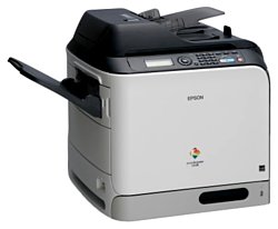
Epson AcuLaser CX28DN
Рейтинг

 Снят с производства
Тип устройства
МФУ
Технология печати
лазерная
Макс. формат
A4
Число страниц в месяц
60000
Скорость печати
A4
24
Цветность печати
цветная
Общие характеристики |
|
|---|---|
Число страниц в месяц |
60 000 |
Область применения |
средний офис |
Тип |
лазерный/светодиодный |
Технология печати |
лазерная |
Тип устройства |
МФУ |
Сканер |
|
Копир |
|
Макс. формат |
A4 |
Цветность печати |
цветная |
Размещение |
настольный |
Телефон |
|
Печать фотографий |
|
Факс |
|
Принтер |
|
Пигментные чернила |
|
Прямая печать |
|
Печать без полей |
|
Система непрерывной подачи чернил |
|
Двусторонняя печать |
|
Время разогрева |
50 |
Макс, разрешение для ч/б печати |
|
| По X | 2 400 |
| По Y | 600 |
Скорость ч/б печати |
|
| A4 | 24 |
Время выхода первого отпечатка |
|
| Ч/б | 18 |
Копир |
|
Макс, количество копий за цикл |
999 |
Время выхода первой копии |
18 |
Шаг масштабирования |
0,01 |
Значение масштаба |
|
| Минимальное | 0,25 |
| Максимальное | 4 |
Макс, разрешение (ч/б) |
|
| По Y | 600 |
| По X | 600 |
Сканер |
|
Оттенки серого |
256 |
Тип датчика сканера |
контактный (CIS) |
Глубина цвета |
48 бит |
Тип сканера |
планшетный/протяжный |
Емкость устройства автоподачи оригиналов |
50 |
Стандарт WIA |
|
Отправка изображения по e-mail |
|
Стандарт TWAIN |
|
Макс. формат оригинала |
A4 |
Устройство автоподачи оригиналов |
одностороннее |
Макс, размер сканирования |
|
| По Y | 355 |
| По X | 216 |
Разрешение сканера |
|
| По Х | 600 |
| По Х (улучшенное) | 9 600 |
| По Y (улучшенное) | 9 600 |
Скорость сканирования |
|
| Цветн, | 18 |
Расходные материалы |
|
Ресурс ч/б картриджа/тонера |
8 000 |
Ресурс фотобарабана |
30 000 |
Ресурс цветного картриджа/тонера |
8 000 |
Печать на: |
|
| Рулоне |
|
| CD/DVD |
|
| Фотобумаге |
|
| Карточках |
|
| Конвертах |
|
| Глянцевой бумаге |
|
| Пленках |
|
| Матовой бумаге |
|
| Этикетках |
|
Плотность бумаги |
|
| Максимальная | 210 |
| Минимальная | 64 |
Факс |
|
PC Fax |
|
Цветной |
|
Телефон |
|
Спикерфон |
|
Стандарт DECT |
|
Автоответчик |
|
Caller ID |
|
АОН |
|
Беспроводная трубка |
|
Проводная трубка |
|
Шрифты и языки управления |
|
Языки управления |
|
| PPDS |
|
|
|
|
| PostScript 2 |
|
| PCL 5e |
|
| PostScript |
|
| PostScript 3 |
|
| PCL 5c |
|
| PCL 6 |
|
Количество установленных шрифтов |
|
| PCL | 93 |
| PostScript | 138 |
Лотки |
|
Подача бумаги |
|
| Максимальная | 850 |
| Стандартная | 350 |
Вывод бумаги |
|
| Стандартный | 250 |
Финишер |
|
Степлер |
|
Электронная сортировка |
|
Сортер |
|
Сортировка со сдвигом |
|
Брошюровщик |
|
Интерфейсы |
|
Wi-Fi 802.11n |
|
LPT |
|
Инфракрасный порт |
|
RS-232 |
|
Устройство для чтения карт памяти |
|
Bluetooth |
|
Wi-Fi |
|
AirPrint |
|
FireWire (IEEE 1394) |
|
USB |
|
Ethernet (RJ-45) |
|
Веб-интерфейс |
|
Версия USB |
2,0 |
Память/Процессор |
|
Частота процессора |
500 |
Объем памяти |
256 |
Макс, объем памяти |
768 |
Дополнительная информация |
|
Работа от аккумулятора |
|
Экран |
|
Мин. системные требования |
Intel Pentium III |
Поддержка ОС |
|
| DOS |
|
| Windows |
|
| Mac OS |
|
| Linux |
|
Потребляемая мощность |
|
| В режиме ожидания | 51 |
| При работе | 790 |
Габариты |
|
Высота |
578 |
Глубина |
590 |
Ширина |
539 |
Вес |
50 |
Модули
MECH-081
MECH-261
CASE-022ADF
MECH-101
MECH-061ADF
MECH-022
MECH-041ADF
MECH-031
MECH-021ADF
CASE-041ADF
MECH-071
MECH-051
MECH-011
MECH-051ADF
MECH-131
CASE-031SC
MECH-031ADF
MECH-181
MECH-041
ELEC-011
CASE-011
MECH-091
MECH-121
MECH-211
MECH-201
MECH-161
CASE-011ADF
MECH-061
MECH-141
CASE-021SC
MECH-151
MECH-171
MECH-011ADF
MECH-191
CASE-031ADF
MECH-111
CASE-011SC
Детали MECH-181

| Деталь: | GUIDE |
| Парткод: | 1510469 |
| Деталь: | REGULATING PLATE |
| Парткод: | 1510470 |
| Деталь: | BRAKE |
| Парткод: | 1510471 |
| Деталь: | GUIDE |
| Парткод: | 1510472 |
| Деталь: | GUIDE |
| Парткод: | 1510473 |
| Деталь: | REGULATING PLATE |
| Парткод: | 1510474 |
| Деталь: | LEVER |
| Парткод: | 1510475 |
| Деталь: | FRICTION SHEET |
| Парткод: | 1242317 |
| Деталь: | REGULATING PLATE ASSY |
| Парткод: | 1510476 |
| Деталь: | HOLDER ASSY |
| Парткод: | 1598892 |
| Деталь: | SEAL |
| Парткод: | 1598893 |
| Деталь: | SEAL |
| Парткод: | 1598894 |
| Деталь: | STOP RING |
| Парткод: | 1009578 |
| Деталь: | GEAR 19T |
| Парткод: | 1598895 |
| Деталь: | LABEL PROHIBITION |
| Парткод: | 1508889 |
| Деталь: | CABLE TIE |
| Парткод: | 1508890 |
| Деталь: | WIRING |
| Парткод: | 2126041 |
| Деталь: | PHOTO INTERRUPTER |
| Парткод: | 2125413 |
| Деталь: | TIMING BELT 200L |
| Парткод: | 1510538 |
| Деталь: | TIMING BELT 152L |
| Парткод: | 1510539 |
| Деталь: | TIMING BELT 180L |
| Парткод: | 1510540 |
| Деталь: | ADF FRAME ASSY |
| Парткод: | 2125414 |
| Деталь: | ADF FRAME ASSY |
| Парткод: | 2130720 |
| Деталь: | ACTUATOR |
| Парткод: | 1510483 |
| Деталь: | ROLLER |
| Парткод: | 1508851 |
| Деталь: | PHOTO INTERRUPTER |
| Парткод: | 2108404 |
| Деталь: | SEPARATION ROLLER ASSY |
| Парткод: | 1508858 |
| Деталь: | SENSOR WIRING/7 |
| Парткод: | 2125862 |
| Деталь: | SWITCH |
| Парткод: | 2144029 |
| Деталь: | WIRE HARNESS ASSY |
| Парткод: | 2125841 |
| Деталь: | WIRE HARNESS ASSY |
| Парткод: | 2125842 |
| Деталь: | PWB ASSY |
| Парткод: | 2125388 |
| Деталь: | PHOTO INTERRUPTER |
| Парткод: | 2108404 |
| Деталь: | LEVER |
| Парткод: | 1510441 |
| Деталь: | DUCT ASSY |
| Парткод: | 1510444 |
| Деталь: | LEVER |
| Парткод: | 1508834 |
| Деталь: | SEPARATION PAD ASSY |
| Парткод: | 1508897 |
| Деталь: | FRICTION SHEET |
| Парткод: | 1510555 |
| Деталь: | ROLLER |
| Парткод: | 1510556 |
| Деталь: | FAN MOTOR |
| Парткод: | 2125389 |
| Деталь: | PHOTO INTERRUPTER |
| Парткод: | 2108404 |
| Деталь: | WIRE HARNESS ASSY |
| Парткод: | 2125846 |
| Деталь: | WIRE HARNESS ASSY |
| Парткод: | 2125847 |
| Деталь: | WIRE HARNESS ASSY |
| Парткод: | 2125848 |
| Деталь: | WIRE HARNESS ASSY |
| Парткод: | 2125849 |
| Деталь: | WIRING |
| Парткод: | 2126045 |
| Деталь: | PWB ASSY |
| Парткод: | 2125419 |
| Деталь: | ACTUATOR |
| Парткод: | 1510549 |
| Деталь: | ACTUATOR |
| Парткод: | 1510550 |
| Деталь: | ROLLER |
| Парткод: | 1510552 |
| Деталь: | PWB ASSY |
| Парткод: | 2125420 |
| Деталь: | WIRING |
| Парткод: | 2126047 |
| Деталь: | MAT ASSY |
| Парткод: | 1508898 |
| Деталь: | SDH COVER ASSY |
| Парткод: | 2125421 |
| Деталь: | 250 SHEET TRAY ASSY |
| Парткод: | 1508849 |
| Деталь: | SEPARATION ROLLER ASSY |
| Парткод: | 1508850 |
| Деталь: | ROLLER |
| Парткод: | 1508851 |
| Деталь: | LEVER |
| Парткод: | 1510467 |
| Деталь: | LABEL PAPER STACK |
| Парткод: | 1510468 |
| Деталь: | HANDLE |
| Парткод: | 1508854 |
| Деталь: | WIRE HARNESS ASSY |
| Парткод: | 2125851 |
| Деталь: | WIRE HARNESS ASSY |
| Парткод: | 2125852 |
| Деталь: | WIRE HARNESS ASSY |
| Парткод: | 2125853 |
| Деталь: | PHOTO INTERRUPTER |
| Парткод: | 2108404 |
| Деталь: | STOP PLATE |
| Парткод: | 1510462 |
| Деталь: | GUIDE PLATE |
| Парткод: | 1510463 |
| Деталь: | Sensor Wiring/2 |
| Парткод: | 2125854 |
| Деталь: | PHOTO SENSING ELEMENT |
| Парткод: | 2125390 |
| Деталь: | GUIDE PLATE |
| Парткод: | 1510464 |
| Деталь: | RAIL |
| Парткод: | 1510465 |
| Деталь: | TRANSFER BELT UNIT |
| Парткод: | 2125391 |
| Деталь: | FAN MOTOR |
| Парткод: | 2125384 |
| Деталь: | FIXING WIRING/3 |
| Парткод: | 2126032 |
| Деталь: | MICRO-SWITCH |
| Парткод: | 2108261 |
| Деталь: | HOLDER |
| Парткод: | 1510436 |
| Деталь: | LEVER |
| Парткод: | 1510437 |
| Деталь: | CLAW |
| Парткод: | 1510438 |
| Деталь: | RUBBER FOOT |
| Парткод: | 1083060 |
| Деталь: | CLAW |
| Парткод: | 1510439 |
| Деталь: | SWITCH |
| Парткод: | 2022925 |
| Деталь: | FIXING WIRING/4 |
| Парткод: | 2126033 |
| Деталь: | GUIDE ASSY |
| Парткод: | 1510557 |
| Деталь: | HINGE |
| Парткод: | 1510430 |
| Деталь: | HINGE |
| Парткод: | 1510432 |
| Деталь: | HOLDER |
| Парткод: | 1510433 |
| Деталь: | HOLDER |
| Парткод: | 1510434 |
| Деталь: | HUMIDITY CONVERTION EL. |
| Парткод: | 2125399 |
| Деталь: | SOLID STATE SWITCH |
| Парткод: | 2077417 |
| Деталь: | PHOTO INTERRUPTER |
| Парткод: | 2108404 |
| Деталь: | SENSOR WIRING/1 |
| Парткод: | 2125868 |
| Деталь: | CLUTCH |
| Парткод: | 2126081 |
| Деталь: | MICRO-SWITCH |
| Парткод: | 2108261 |
| Деталь: | SOLID STATE SWITCH |
| Парткод: | 2125400 |
| Деталь: | GEAR 15T |
| Парткод: | 1508870 |
| Деталь: | LEVER |
| Парткод: | 1508871 |
| Деталь: | GEAR 17T |
| Парткод: | 1508872 |
| Деталь: | CONTROLLER FLAT CABLE/1 |
| Парткод: | 2125877 |
| Деталь: | PWB ASSEMBLY(PWB-A ASSY) |
| Парткод: | 2125497 |
| Деталь: | FAN MOTOR |
| Парткод: | 2125410 |
| Деталь: | CONTROLLER |
| Парткод: | 2134195 |
| Деталь: | CONTROLLER(PP SEC WW) |
| Парткод: | 2139092 |
| Деталь: | FLAT CABLE |
| Парткод: | 2125878 |
| Деталь: | WIRE HARNESS ASSY |
| Парткод: | 2125879 |
| Деталь: | DOOR |
| Парткод: | 1508798 |
| Деталь: | COVER |
| Парткод: | 1508799 |
| Деталь: | REAR COVER |
| Парткод: | 1508800 |
| Деталь: | COVER |
| Парткод: | 1508801 |
| Деталь: | CLEANING PAD |
| Парткод: | 1510380 |
| Деталь: | CLEANING MATERIAL |
| Парткод: | 1510381 |
| Деталь: | COVER |
| Парткод: | 1508802 |
| Деталь: | FRONT COVER ASSY |
| Парткод: | 1615210 |
| Деталь: | LEVER |
| Парткод: | 1510383 |
| Деталь: | COVER |
| Парткод: | 1508804 |
| Деталь: | LEFT COVER ASSY |
| Парткод: | 1508805 |
| Деталь: | COVER |
| Парткод: | 1508806 |
| Деталь: | COVER |
| Парткод: | 1508855 |
| Деталь: | REGULATING PLATE |
| Парткод: | 1510477 |
| Деталь: | REGULATING PLATE |
| Парткод: | 1510478 |
| Деталь: | TRAY ASSY |
| Парткод: | 1508856 |
| Деталь: | TRAY |
| Парткод: | 1508857 |
| Деталь: | FRICTION SHEET |
| Парткод: | 1510479 |
| Деталь: | LEVER |
| Парткод: | 1510480 |
| Деталь: | LEVER |
| Парткод: | 1510481 |
| Деталь: | SENSOR WIRING/9 |
| Парткод: | 2125860 |
| Деталь: | LEVER |
| Парткод: | 1510482 |
| Деталь: | SENSOR WIRING/10 |
| Парткод: | 2125861 |
| Деталь: | FAN MOTOR |
| Парткод: | 2108356 |
| Деталь: | ROLLER |
| Парткод: | 1510487 |
| Деталь: | ROLL |
| Парткод: | 1510488 |
| Деталь: | PHOTO INTERRUPTER |
| Парткод: | 2108404 |
| Деталь: | TRANSFER ROLLER |
| Парткод: | 1508860 |
| Деталь: | CLAW |
| Парткод: | 1510489 |
| Деталь: | SEAL |
| Парткод: | 1508885 |
| Деталь: | WIRE HARNESS ASSY |
| Парткод: | 2125869 |
| Деталь: | HV TRANSFORMER |
| Парткод: | 2125408 |
| Деталь: | PAPERFEED WIRING/3 |
| Парткод: | 2125870 |
| Деталь: | HV TRANSFORMER |
| Парткод: | 2125409 |
| Деталь: | WIRE HARNESS ASSY |
| Парткод: | 2125871 |
| Деталь: | POWER SUPPLY WIRING/3 |
| Парткод: | 2148984 |
| Деталь: | BRUSHLESS MOTOR/30 |
| Парткод: | 2125405 |
| Деталь: | Brushless motor |
| Парткод: | 2125406 |
| Деталь: | CLUTCH |
| Парткод: | 2126080 |
| Деталь: | LEVER |
| Парткод: | 1510506 |
| Деталь: | PAPER TAKE-UP DRIVE ASSY |
| Парткод: | 2126083 |
| Деталь: | GEAR 19T |
| Парткод: | 1508877 |
| Деталь: | GEAR 19T |
| Парткод: | 1508878 |
| Деталь: | GEAR 27T |
| Парткод: | 1508879 |
| Деталь: | MAIN DRIVE ASSY |
| Парткод: | 2126084 |
| Деталь: | PHOTO INTERRUPTER |
| Парткод: | 2108404 |
| Деталь: | GUIDE |
| Парткод: | 1510499 |
| Деталь: | ROLL |
| Парткод: | 1510500 |
| Деталь: | Neutralizing Brush |
| Парткод: | 1510501 |
| Деталь: | LEVER |
| Парткод: | 1508864 |
| Деталь: | TOP COVER |
| Парткод: | 1508887 |
| Деталь: | TRAY |
| Парткод: | 1508888 |
| Деталь: | RUBBER FOOT |
| Парткод: | 1510535 |
| Деталь: | POWER SUPPLY/230V |
| Парткод: | 2135910 |
| Деталь: | PHOTO INTERRUPTER |
| Парткод: | 2108404 |
| Деталь: | Relay harness |
| Парткод: | 2125855 |
| Деталь: | PRINT HEAD ASSY |
| Парткод: | 2125394 |
| Деталь: | SENSOR WIRING/4 |
| Парткод: | 2125856 |
| Деталь: | ACTUATOR |
| Парткод: | 1510466 |
| Деталь: | SEAL |
| Парткод: | 1508862 |
| Деталь: | SENSOR WIRING/15 |
| Парткод: | 2125867 |
| Деталь: | PHOTO INTERRUPTER |
| Парткод: | 2108404 |
| Деталь: | ACTUATOR |
| Парткод: | 1508863 |
| Деталь: | PANEL SHEET(FRENCH) |
| Парткод: | 1508812 |
| Деталь: | COVER/IR |
| Парткод: | 1508813 |
| Деталь: | PANEL ASSY |
| Парткод: | 2125395 |
| Деталь: | TIMING BELT 500L |
| Парткод: | 1510492 |
| Деталь: | TIMING BELT 354L |
| Парткод: | 1510493 |
| Деталь: | TIMING BELT 190L |
| Парткод: | 1510494 |
| Деталь: | ROLLER |
| Парткод: | 1510495 |
| Деталь: | ROLLER |
| Парткод: | 1510496 |
| Деталь: | GUIDE |
| Парткод: | 1510497 |
| Деталь: | ROLLER |
| Парткод: | 1510498 |
| Деталь: | FUSING UNIT 230V |
| Парткод: | 2125398 |
| Деталь: | Cover/Upper |
| Парткод: | 1508892 |
| Деталь: | PICK-UP ROLLER |
| Парткод: | 1508893 |
| Деталь: | ROLLER |
| Парткод: | 1508894 |
| Деталь: | FOOK/RIGHT |
| Парткод: | 1510541 |
| Деталь: | ACTUATOR |
| Парткод: | 1510543 |
| Деталь: | ACTUATOR |
| Парткод: | 1510544 |
| Деталь: | PWB ASSY |
| Парткод: | 2125417 |
| Деталь: | WIRING |
| Парткод: | 2126043 |
| Деталь: | CLUTCH |
| Парткод: | 1508895 |
| Деталь: | HOOK/LEFT |
| Парткод: | 1510546 |
| Деталь: | HANDLE |
| Парткод: | 1508896 |
| Деталь: | COVER ASSY |
| Парткод: | 2125418 |
| Деталь: | PICK UP ROLLER ASSY |
| Парткод: | 1516573 |
| Деталь: | MOTOR |
| Парткод: | 2125404 |
| Деталь: | HOPPER DRIVE ASSY |
| Парткод: | 2126068 |
| Деталь: | WASTE TONER DRIVE ASSY |
| Парткод: | 1510503 |
| Деталь: | REGULATING PLATE/RIGHT |
| Парткод: | 1510561 |
| Деталь: | LABEL MAX LEVEL |
| Парткод: | 1510562 |
| Деталь: | REGULATING PLATE/LEFT |
| Парткод: | 1510563 |
| Деталь: | Neutralizing Brush |
| Парткод: | 1510564 |
| Деталь: | LABEL INDICATION |
| Парткод: | 1510565 |
| Деталь: | TRAY |
| Парткод: | 1510567 |
| Деталь: | PHOTO INTERRUPTER |
| Парткод: | 2108404 |
| Деталь: | ACTUAOTR |
| Парткод: | 1510485 |
| Деталь: | SOLID STATE SWITCH |
| Парткод: | 2036389 |
| Деталь: | CLUTCH |
| Парткод: | 2126080 |
| Деталь: | CONVEYANCE WIRING/1 |
| Парткод: | 2125864 |
| Деталь: | CONVEYANCE WIRING/3 |
| Парткод: | 2125865 |
| Деталь: | WIRING |
| Парткод: | 2126028 |
| Деталь: | TAPE |
| Парткод: | 1508807 |
| Деталь: | WIRING |
| Парткод: | 2126029 |
| Деталь: | WIRING |
| Парткод: | 2126030 |
| Деталь: | PWB ASSY |
| Парткод: | 2125364 |
| Деталь: | GROUND |
| Парткод: | 1510393 |
| Деталь: | FRAME |
| Парткод: | 1510394 |
| Деталь: | TAPE |
| Парткод: | 1510395 |
| Деталь: | TIMING BELT |
| Парткод: | 1510396 |
| Деталь: | FLAT CABLE |
| Парткод: | 2125365 |
| Деталь: | MOTOR |
| Парткод: | 2125366 |
| Деталь: | COVER/ADF |
| Парткод: | 1510397 |
| Деталь: | WIRING |
| Парткод: | 2126031 |
| Деталь: | EXPOSURE UNIT |
| Парткод: | 2126079 |
| Деталь: | REED SWITCH |
| Парткод: | 2125367 |
| Деталь: | OPTICAL UNIT |
| Парткод: | 2133206 |
| Деталь: | LEVER |
| Парткод: | 1510398 |
Коды ошибок
0010
0017
0018
001B
0045
0046
004A
004C
004E
0060
0094
0096
0300
0310
0500
0502
0503
0510
0520
0650
0F50
0F52
0F53
0F54
0F55
1038
13C0
13DD
13E2
13E3
13F0
14A3
3C00 ... 3C10
3FFF
4FFF
C002
C003
C013
C015
C022
C025
C026
C027
C050
C051
C052
C053
C060
CF01
FFFF
Описание
| Error code: | 0010 |
| Display: | P MOTOR 1 |
| Description: | Network I/F Initialize has not been completed. |
| Causes: | Network I/F does not work correctly. Firmware for Network I/F is not installed. |
| Remedy: | Check the firmware is installed into Network I/F. Main Board replacement |
| Error code: | 0017 |
| Display: | P MOTOR 2 |
| Description: | Intermediate transport motor malfunction • The intermediate transport motor does not rotate evenly even after the lapse of a given period of time while it is being started. • The motor lock signal remains HIGH for a given period of consecutive time while the intermediate transport motor is being rotated. |
| Causes: | • Transport motor (M2) • Printer control board (PRCB) |
| Remedy: | 1 Check the M3 connector for proper connection and correct as necessary. 2 Check M3 for proper drive coupling and correct as necessary. 3 Check the MFPB connector for proper connection and correct as necessary. 4 M3 operation check MFPB PJ27MFPB-3 to 7 C-5. 5 Change M3. 6 Change MFPB. 7 Change DCPU. |
| Error code: | 0018 |
| Display: | D MOTOR 2 |
| Description: | Color PC Drum Motor’s failure to turn • The Motor Lock signal remains HIGH for a predetermined continuous period of time while the Motor is turning. |
| Causes: | • Developing motor (M1) • Printer control board (PRCB) |
| Remedy: | 1 Check the connector of motor for proper connection and correct as necessary. 2 Check the connector of motor for proper drive coupling and correct as necessary. 3 Check the PWB-M connector for proper connection and correct as necessary. 4 M2 operation check PWB-M CNDM3-5 (REM) PWB-M CNDM3-8 (LOCK) C-23. 5 Change PWB-M. |
| Error code: | 001B |
| Display: | Toner rack failure CODE (001B) Turn power off, on |
| Description: | Toner Rack Failure |
| Causes: | • Rack Positioning Sensor, PL5.1.12 • Engine Control Board, PL13.0.20 |
| Remedy: | 1 Check the Rack Motor connector P/J5 on the Engine Control Board. Is the connector seated properly? Go to step 2. Reseat the connector. If the problem persists, go to step 2. 2 Check the Engine Control Board connector P/J5. Is the connector seated properly? Go to step 3. Reseat the connector. If the problem persists, go to step 3. 3 Check the Rack Positioning Sensor at PJ5-11. Is the sensor on? Go to step 4. Replace the sensor. If the problem persists, go to step 4. 4 Replace the Engine Control Board. Complete. |
| Error code: | 0045 |
| Display: | Scanner fan failure CODE (0045) Turn power off, on |
| Description: | Scanner Fan Failure • The Exit Tray Cooling Fan Motor does not rotate evenly even after the lapse of a given period of time while it is being started. • The fan motor lock signal remains HIGH for a given period of consecutive time while the exit tray cooling fan motor is being rotated. |
| Causes: | • Engine Control Board, PL13.0.20 • Image Processor Board, PL2.0.4 |
| Remedy: | 1 Check the Engine Control Board connector P/J24. Is the connector seated properly? Go to step 2. Reseat the connector. If the problem persists, go to step 2. 2 Clean the Exit Tray Cooling Fan air intake Check the fan for possible overload and correct as necessary. Does the problem persist? Go to step 3. Complete. 3 Replace the Exit Tray Cooling Fan. NOTE During replacement, check if the fan is obstructed and correct if necessary. If the problem persists, replace the fan. Does the problem persist? Go to step 3. Complete. 4 Replace the Image Processor Board. Complete. |
| Error code: | 0046 |
| Display: | FUSER FAN |
| Description: | Fusing Cooling Fan Motor/1’s failure to turn • The Fan Lock signal remains HIGH for a predetermined continuous period of time while the Motor remains stationary. |
| Causes: | Fusing cooling fan motor (FM1) Print control board (PRCB) |
| Remedy: | 1 Check the connector of motor for proper connection and correct as necessary. 2 Check the fan for possible overload and correct as necessary. 3 M11 operation check PWB-M CNDM1-12 (ON) PWB-M CNDM1-14 (LOCK) K to L-1 to 2. 4 Change PWB-M. |
| Error code: | 004A |
| Display: | Duplex fan failure CODE (004A) Turn power off, on |
| Description: | Duplex Unit Fan Failure The Duplex Unit Fan Motor lock signal remains HIGH for a predetermined consecutive period of time while the cooling fan motor remains energized. |
| Causes: | • Engine Control Board, PL13.0.20 • Duplex Unit, PL14.1 |
| Remedy: | 1 Check the Engine Control Board connector P/J21. Is the connector seated properly? Go to step 2. Reseat the connector. If the problem persists, go to step 2. 2 Replace the Engine Control Board. Does the problem persist? Go to step 3. Complete. 3 Replace the Duplex Unit. Complete. |
| Error code: | 004C |
| Display: | Exhaust fan failure CODE (004C) Turn power off, on |
| Description: | Exhaust Fan Failure The Ventilation Fan Motor does not rotate evenly even after the lapse of a given period of time while it is starting. |
| Causes: | • Ventilation Fan Motor, PL7.2.20 • Engine Control Board, PL13.0.20 • Power Supply, PL13.0.17 |
| Remedy: | 1 Check the Engine Control Board connector P/J16. Is the connector seated properly? Go to step 2. Reseat the connector. If the problem persists, go to step 2. 2 Check the operation of the Ventilation Fan Motor. Is the motor faulty? Replace the motor. If the problem persists, go to step 5. Go to step 5. 3 On the Engine Control Board, check for +24 VDC at P/J2-1, 5, and 7. Check for +5 VDC at P/J2-2. Are the voltages present and within specification? Go to step 4. Replace the Power Supply. If the problem persists, go to step 4. 4 Replace the Engine Control Board. Complete. |
| Error code: | 004E |
| Display: | LVPS fan failure CODE (004E) Turn power off, on |
| Description: | LVPS Fan Failure • The Power Supply Cooling Fan Motor does not rotate evenly even after the lapse of a given period of time while it is being started. • The motor lock signal remains HIGH for a given period of consecutive time while the Power Supply Cooling Fan Motor is being rotated. |
| Causes: | • Power Supply Cooling Fan Motor, PL12.0.11 • Engine Control Board, PL13.0.20 • Power Supply, PL13.0.17 |
| Remedy: | 1 Check the High Voltage Board connectors CN1 and CN2, and the Engine Control Board connector P/J17. Are the connectors seated properly? Go to step 2. Reseat the connector(s). If the problem persists, go to step 2. 2 Check the Power Supply Cooling Fan Motor control signals at CN2. Are the signals operating correctly? Replace the motor. If the problem persists, go to step 3. Go to step 3. 3 Check the Power Supply Cooling Fan Motor control signals at PJ17 on the Engine Control Board. Are the control signals operating correctly? Replace the High Voltage Board. If the problem persists, go to step 4. Go to step 4. 4 On the Engine Control Board, check for +24 VDC at P/J2-1, 5, and 7. Check for +5 VDC at P/J2-2. Are the voltages present and within specification? Go to step 5. Replace the Power Supply. If the problem persists, go to step 5. 5 Replace the Engine Control Board. Complete. |
| Error code: | 0060 |
| Display: | FUSER MOTOR |
| Description: | Engine PWB mismatch Unmatching engine and engine sub boards. Defective engine subboard |
| Causes: | Defective engine sub PWB. |
| Remedy: | Engine PWB 1. Turn the main power swtch off and after 5 seconds, then turn power on. 2. Replace the engine PWB. |
| Error code: | 0094 |
| Display: | Trans. roll failure CODE (0094) Turn power off, on |
| Description: | Transfer Roll Failure Possible causes: • The 2nd Image Transfer Retraction Position Sensor(PS3) is not activated (retracted position) within a given period of time after the retraction sequence of the 2nd transfer roller has been started. • The 2nd Image Transfer Retraction Position Sensor is not deactivated (pressed position) within a given period of time after the pressure sequence of the 2nd transfer roller has been started. |
| Causes: | • 2nd Image Transfer Retraction Position Sensor (PS3), PL4.0.9 • 2nd Image Transfer Retraction Position Solenoid (SD4), PL7.2.23 • Main Motor, PL9.1.6 • Engine Control Board, PL13.0.20 |
| Remedy: | 1 Check the Main Motor connector CN37. Is the connector seated properly? Go to step 2. Reseat the connector. If the problem persists, go to step 2. 2 Check the Main Motor for proper drive coupling and correct as necessary. Does the problem persist? Go to step 3. Complete. 3 Check the 2nd Image Transfer Retraction Position Solenoid connector CN5. Is the connector seated properly? Go to step 4. Reseat the connector. If the problem persists, go to step 4. 4 Check the 2nd Image Transfer Retraction Position Solenoid for proper drive coupling and correct as necessary. Does the problem persist? Go to step 5. Complete. 5 Check the 2nd Image Transfer Retraction Position Sensor control signal for a voltage change at P/J12-3 on the Engine Control Board. Is the signal operating correctly? Go to step 6. Replace the Engine Control Board. If the problem persists, go to step 6. 6 Replace the 2nd Image Transfer Retraction Position Solenoid. Does the problem persist? Go to step 7. Complete. 7 Replace the 2nd Image Transfer Retraction Position Sensor. Complete. |
| Error code: | 0096 |
| Display: | XFER DETACH 1 |
| Description: | Transfer Belt Separation • The 1st Image Transfer Pressure/Retraction Position Sensor doesn’t turn ON (Retracting) even after the lapse of a given period of time after the 1st Image Transfer Pressure/Retraction Clutch has turned ON during the Transfer Belt is retracting. • The 1st Image Transfer Pressure/Retraction Position Sensor doesn’t turn OFF (Pressuring) even after the lapse of a given period of time after the 1st Image Transfer Pressure/Retraction Clutch has turned ON during the Transfer Belt is pressuring. |
| Causes: | • 1st transfer pressure sensor (PS17) • Transport motor (M2) • 1st transfer pressure solenoid (SD1) • Printer control board (PRCB) |
| Remedy: | 1 Check the M1 connector for proper connection and correct as necessary. 2 PC6 I/O check, Sensor check 3 CL3 operation check PWB-M CNDM1-11 (ON) K to L-2. 4 M1 operation check PWB-M CNDM1-5 (REM) PWB-M CNDM1-8 (LOCK) K to L-2. 5 Change PWB-M. |
| Error code: | 0300 |
| Display: | POLYGON MOTOR |
| Description: | Polygon motor malfunction |
| Causes: | • The polygon motor does not rotate evenly even after the lapse of a given period of time after it has been started. • The motor lock signal remains HIGH for a given period of consecutive time while the polygon motor is being rotated. |
| Remedy: | 1 Check the cable and connector for proper connection and correct as necessary. - - 2 Change PH unit. - - 3 Change PRCB. - - |
| Error code: | 0310 |
| Display: | LASER ERROR |
| Description: | Laser malfunction |
| Causes: | • The SOS signal is not detected within a given period of time after the output of the laser has been started. |
| Remedy: | 1 Check the cable and connector for proper connection and correct as necessary. - - 2 Change PH unit. - - 3 Change PRCB. - - |
| Error code: | 0500 |
| Display: | FUSER ERROR |
| Description: | Fuser warm-up failure |
| Causes: | • The thermistor /1 does not detect the specified temperature and the warm-up cycle is not completed even after the lapse of a given period of time after the cycle has been started. |
| Remedy: | 1 Change fuser unit. - - 2 For C110: 1. Main switch is turned ON. 2. Open the top cover. 3. Press the following keys in this order. ROTATE TONER key -ATTENTION key - ATTENTION key - ROTATE TONER key. 4. Main switch is turned OFF/ON. For C130n: 1. Main switch is turned ON. 2. Execute [SERVICE MENU] - [FUSER UNLOCK]. See P.103 - - 3 Change PRCB. - - 4 Change DCPU. - - |
| Error code: | 0502 |
| Display: | Thermistor failure CODE (0502) Turn power off, on |
| Description: | 0502 Thermistor Failure, 0510 Fuser Failure, and 0520 Fuser Failure 0502 Thermistor Failure The temperature detected by the thermistor does not reach an expected level after the warm-up cycle starts. |
| Causes: | • Fuser, PL4.0.13 • Engine Control Board, PL13.0.20 • Power Supply, PL13.0.17 |
| Remedy: | 1 Check that the Fuser is installed correctly. Does the problem persist? Go to step 2. Complete. 2 Check the Engine Control Board connectors P/J2, P/J3, and P/J6. Are the connectors seated properly? Go to step 3 Reseat the connectors. If the problem persists, go to step 3. 3 Check the Low Voltage Power Supply connectors CN3, CN5, and CN7. Are the connectors seated properly? Go to step 4. Reseat the connectors. If the problem persists, go to step 4. 4 Replace the Fuser (8-9). Does the problem persist? Go to step 5. Complete. 5 Replace the Engine Control Board. Does the problem persist? Go to step 6. Complete. 6 Replace the Power Supply. Complete. |
| Error code: | 0503 |
| Display: | TERMISTOR2 |
| Description: | Thermistor resistance failure |
| Causes: | • The difference between the temperature detected by thermistor/1 and that detected by thermistor/2 exceeds a predetermined value. |
| Remedy: | 1 Change fuser unit. - - 2 For C110: 1. Main switch is turned ON. 2. Open the top cover. 3. Press the following keys in this order. ROTATE TONER key -ATTENTION key - ATTENTION key - ROTATE TONER key. 4. Main switch is turned OFF/ON. For C130n: 1. Main switch is turned ON. 2. Execute [SERVICE MENU] - [FUSER UNLOCK]. See P.103 - - 3 Change PRCB. - - 4 Change DCPU. - - |
| Error code: | 0510 |
| Display: | Fuser failure CODE (0510) Turn power off, on |
| Description: | 0502 Thermistor Failure, 0510 Fuser Failure, and 0520 Fuser Failure 0510 Fuser Failure The temperature detected by the thermistor remains lower than expected for a given period of time or longer. |
| Causes: | • Fuser, PL4.0.13 • Engine Control Board, PL13.0.20 • Power Supply, PL13.0.17 |
| Remedy: | 1 Check that the Fuser is installed correctly. Does the problem persist? Go to step 2. Complete. 2 Check the Engine Control Board connectors P/J2, P/J3, and P/J6. Are the connectors seated properly? Go to step 3 Reseat the connectors. If the problem persists, go to step 3. 3 Check the Low Voltage Power Supply connectors CN3, CN5, and CN7. Are the connectors seated properly? Go to step 4. Reseat the connectors. If the problem persists, go to step 4. 4 Replace the Fuser (8-9). Does the problem persist? Go to step 5. Complete. 5 Replace the Engine Control Board. Does the problem persist? Go to step 6. Complete. 6 Replace the Power Supply. Complete. |
| Error code: | 0520 |
| Display: | Fuser failure CODE (0520) Turn power off, on |
| Description: | 0502 Thermistor Failure, 0510 Fuser Failure, and 0520 Fuser Failure 0520 Fuser Failure The temperature detected by the thermistor remains higher than expected for a given period of time or longer. |
| Causes: | • Fuser, PL4.0.13 • Engine Control Board, PL13.0.20 • Power Supply, PL13.0.17 |
| Remedy: | 1 Check that the Fuser is installed correctly. Does the problem persist? Go to step 2. Complete. 2 Check the Engine Control Board connectors P/J2, P/J3, and P/J6. Are the connectors seated properly? Go to step 3 Reseat the connectors. If the problem persists, go to step 3. 3 Check the Low Voltage Power Supply connectors CN3, CN5, and CN7. Are the connectors seated properly? Go to step 4. Reseat the connectors. If the problem persists, go to step 4. 4 Replace the Fuser (8-9). Does the problem persist? Go to step 5. Complete. 5 Replace the Engine Control Board. Does the problem persist? Go to step 6. Complete. 6 Replace the Power Supply. Complete. |
| Error code: | 0650 |
| Display: | Scanner home failure CODE (0650) Turn power off, on |
| Description: | Scanner Home Failure • A low motor lock signal is not detected even after the lapse of a predetermined period of time after the Polygon Motor has been started. • The motor lock signal remains HIGH for a predetermined consecutive period of time while the Polygon Motor remains energized. |
| Causes: | • Engine Control Board, PL13.0.20 • Image Processor Board, PL2.0.4 |
| Remedy: | 1 Check connector P/J2 on the Image Processor Board. Is the connector seated properly? Go to step 2. Reseat the connector. If the problem persists, go to step 2. 2 Replace the Scanner. Does the problem persist? Go to step 3. Complete. 3 Replace the Engine Control Board. Does the problem persist? Go to step 4. Complete. 4 Replace the Power Supply. Complete. |
| Error code: | 0F50 |
| Display: | PT SENSOR |
| Description: | OHP sensor malfunction • It is determined that the OHP sensor is faulty through a check made at the end of the predrive. |
| Causes: | OHP sensor (PS7) Print control board (PRCB) |
| Remedy: | 1 Check the PRCB connector for proper connection and correct as necessary. 2 PS7 sensor check PRCB PJ15-5 (ON) C to D-6. 3 Change PRCB. |
| Error code: | 0F52 |
| Display: | TE SENSOR Y |
| Description: | Toner level sensor /Y malfunction • An error occurs on the toner level sensor board (TLSB). |
| Causes: | • Toner level sensor/Y (PS13) • Printer control board (PRCB) |
| Remedy: | 1 Check the TLSB and MFPB for proper connection and correct as necessary. 2 Change TLSB. 3 Change MFPB. |
| Error code: | 0F53 |
| Display: | TE SENSOR M |
| Description: | Toner level sensor /M malfunction • An error occurs on the toner level sensor board (TLSB). |
| Causes: | • Toner level sensor/M (PS14) • Printer control board (PRCB) |
| Remedy: | 1 Check the TLSB and MFPB for proper connection and correct as necessary. 2 Change TLSB. 3 Change MFPB. |
| Error code: | 0F54 |
| Display: | TE SENSOR C |
| Description: | Toner level sensor /C malfunction • An error occurs on the toner level sensor board (TLSB). |
| Causes: | • Toner level sensor/C (PS15) • Printer control board (PRCB) |
| Remedy: | 1 Check the TLSB and MFPB for proper connection and correct as necessary. 2 Change TLSB. 3 Change MFPB. |
| Error code: | 0F55 |
| Display: | TE SENSOR K |
| Description: | Toner level sensor /K malfunction • An error occurs on the toner level sensor board (TLSB). |
| Causes: | • Toner level sensor/K (PS16) • Printer control board (PRCB) |
| Remedy: | 1 Check the TLSB and MFPB for proper connection and correct as necessary. 2 Change TLSB. 3 Change MFPB. |
| Error code: | 1038 |
| Display: | Interface failure CODE (1038) Turn power off, on |
| Description: | Interface Failure. • Engine Control Board to Image Processor Board connection failure. • The copier determines that there is an error if the Engine Control Board fails to send an acknowledgement signal to the Image Processor Board for a given period of time or more. • An error command signal is transmitted from the Image Processor Board to Engine Control Board. • An error status signal is transmitted from the Engine Control Board to Image Processor Board. |
| Causes: | • Engine Control Board, PL13.0.20 • Image Processor Board, PL2.0.4 |
| Remedy: | 1 Check every connector on the Engine Control Board and the Image Processor Board. Are the connectors seated properly? Go to step 2. Reseat the connectors. If the problem persists, go to step 2. 2 Replace the Image Processor Board. Does the problem persist? Go to step 3. Complete. 3 Change the Engine Control Board. Complete. |
| Error code: | 13C0 |
| Display: | Engine board failure CODE (13C0) Turn power off, on |
| Description: | Print Control Board Malfunction |
| Causes: | • Engine Control Board, PL13.0.20 |
| Remedy: | 1 Replace the Engine Control Board. Complete. |
| Error code: | 13DD |
| Display: | Initial toner failed CODE (13DD) Replace toner Contact Xerox for unit exchange |
| Description: | Initial Toner Failure The printer determines that an initial toner cartridge has been installed. The printer is programmed to only use initial toner cartridges one time. |
| Remedy: | Install a Xerox Standard or High Capacity cartridge. |
| Error code: | 13E2 |
| Display: | Engine ROM failure CODE (13E2) Turn power off, on |
| Description: | Engine ROM Failure Flash ROM writing is found faulty during a check. |
| Causes: | • Engine Control Board, PL13.0.20 • Image Processor Board, PL2.0.4 |
| Remedy: | 1 Check the Engine Control Board connectors. Are the connectors seated properly? Go to step 2. Reseat the connectors. If the problem persists, go to step 2. 2 Replace the Engine Control Board. Does the problem persist? Go to step 3. Complete. 3 Replace the Image Processor Board. Complete. |
| Error code: | 13E3 |
| Display: | FLASH DEVICE |
| Description: | Flash ROM device fault • An erase error occurs during erasing of data in flash ROM. |
| Causes: | • Printer control board (PRCB) • MFP board (MFPB) |
| Remedy: | 1 Check the MFPB for proper connection and correct as necessary. 2 Change PRCB. 3 Change MFPB. |
| Error code: | 13F0 |
| Display: | ENGINE ERR |
| Description: | Engine control failure |
| Causes: | • An undefined malfunction occurs in the engine section (PRCB, etc.). |
| Remedy: | 1 Check the cable and connector for proper connection and correct as necessary. - - 2 Change PRCB. - - 3 Change MFPB. |
| Error code: | 14A3 |
| Display: | Scanner head failure CODE (14A3) Turn power off, on |
| Description: | Scanner Head Failure The intensity of the light emitted from the exposure lamp of the scanner falls short of the specified value. |
| Causes: | • Scanner, PL2.0.4 • Image Processor Board, PL13.0.29/30 |
| Remedy: | 1 Check the connectors on the Image Processor Board. Are the connectors seated properly? Go to step 2. Reseat the connectors. If the problem persists, go to step 2. 2 Replace the Scanner. Does the problem persist? Go to step 3. Complete. 3 Change the Image Processor Board. Complete. |
| Error code: | 3C00 ... 3C10 |
| Description: | Trouble related to security • Contact the responsible people of KONICA MINOLTA when not returning in power switch OFF/ON. |
| Error code: | 3FFF |
| Display: | Control ROM failure CODE (3FFF) Turn power off, on |
| Description: | Control ROM Failure • The copier determines that there is an error if writing to the flash ROM fails during upgrading of the firmware. • When the power switch is turned ON, the error indicator lights up steadily and a corresponding message appears on the display. • If this error message appears, no operations are possible. It is not possible to upgrade the firmware from a PC connected through USB connection. |
| Causes: | • Engine Control Board, PL13.0.20 • Image Processor Board, PL13.0.29/30 |
| Remedy: | 1 Identify the specific firmware that is responsible for the error, and then rewrite the firmware. Does the problem persist? Go to step 2. Complete. 2 Unplug the NVRAM chip on the Engine Control Board, and then plug the chip back in. Does the problem persist? Go to step 3. Complete. 3 Change the Engine Control Board. Does the problem persist? Go to step 4. Complete. 4 Change the Image Processor Board. Complete. |
| Error code: | 4FFF |
| Description: | Controller connect error • MFP board/1 (MFPB/1) to MFP board/2 (MFPB/2) connection failure. |
| Causes: | MFP board/1 (MFPB/1) MFP board/2 (MFPB/2) |
| Remedy: | 1 Turn OFF and ON the power switch. 2 Check the MFPB/1 connector for proper connection and correct as necessary. 3 Check the MFPB/2 connector for proper connection and correct as necessary. 4 Check for proper connection between MFPB/1 and MFPB/2 and correct as necessary. 5 Change MFPB/2. 6 Change MFPB/1. |
| Error code: | C002 |
| Display: | RAM ERROR |
| Description: | RAM (standard) error at startup • RAM error at Standard Memory is detected during printer start-up. |
| Causes: | • MFP board (MFPB) • Standard memory |
| Remedy: | 1 Turn OFF the Power Switch of the printer and turn it ON again (Restart of the printer.) 2 Check connection state of the extension memory and correct as necessary. 3 Check the PWB-P connector for proper connection and correct as necessary. 4 Change the extension memory. 5 Change PWB-P. |
| Error code: | C003 |
| Display: | RAM ERROR |
| Description: | Memory copy PCB 2 problem* 1 • Problems with data from memory copy PCB 2. |
| Causes: | Defective memory copy PCB 2. |
| Remedy: | Replace memory copy PCB 2 and check for correct operation. |
| Error code: | C013 |
| Display: | H/W ADDRESS |
| Description: | MAC address error at startup (MAC address is invalid) • Invalid Mac address is detected during printer start-up. |
| Causes: | MFP board (MFPB) |
| Remedy: | 1 Turn OFF the Power Switch of the printer and turn it ON again (Restart of the printer.) 2 Check the PWB-P connector for proper connection and correct as necessary. 3 Change PWB-P. |
| Error code: | C015 |
| Display: | BOOT ROM |
| Description: | Backup memory read/write problem (engine PCB) • Read and write data does not match. |
| Causes: | Defective backup RAM or engine PCB. |
| Remedy: | Replace the engine PCB and check for correct operation. |
| Error code: | C022 |
| Display: | NVRAM ERROR |
| Description: | Developer unit mixer motor-YMC locking error: The developer unit mixer motor-YMC is not rotating normally |
| Causes: | Developer unit mixer motor-YMC LGC board |
| Remedy: | (1) Pull out the EPU tray and perform the output check (03-115) to check if the 3 outputs of the YMCdeveloper unit mixer are rotating normally. When it is not rotating (2) Is the connector of the YMC-developer unit mixer motor connected securely? (3) Check if the harness or connector of the YMC-drum motor is disconnected or open-circuited. (4) Check if the YMC-developer unit mixer motor is abnormal. (5) Check if the drive gear array has any abnormality such as breakage. When it is rotating (6) Check if developer material is excessively supplied to each YMC-developer unit. (7) Check if the drive gear array of each YMC-developer unit has any abnormality such as breakage. |
| Error code: | C025 |
| Display: | CONTROLLER ROM |
| Description: | Controller ROM error • Lead error of destination setting file is detected during the printer starting. |
| Causes: | MFP board (MFPB) |
| Error code: | C026 |
| Display: | CONTROLLER ROM |
| Description: | Memory PCB communication problem • There is no reply after five retries at transmitting. • There is no reply after five retries at receiving. |
| Causes: | Poor contact in the connector terminals. Defective main PCB or memory PCB. |
| Remedy: | Check the connection of connector CN3 on the main PCB and the connector on memory PCB. Repair or replace if necessary. Replace the main PCB or memory PCB and check for correct operation. |
| Error code: | C027 |
| Display: | CONTROLLER ROM |
| Description: | Controller ROM error • Final check sum error is detected during the printer starting. |
| Causes: | MFP board (MFPB) |
| Remedy: | 1 Turn OFF the Power Switch of the printer and turn it ON again (Restart of the printer.) 2 Check the PWB-P connector for proper connection and correct as necessary. 3 If this error message is displayed after update of firmware, conduct the firmware update procedures again. 4 Change PWB-P. |
| Error code: | C050 |
| Display: | HDD ERROR |
| Description: | Optional second paper feeder communication problem • Communication fails five times successively. |
| Causes: | Paper feeder installed incorrectly. Defective main PCB or drawer main PCB. |
| Remedy: | Check the installation state of the paper feeder and adjust it if it is not properly installed. Replace the main PCB or drawer main PCB and check for correct operation. |
| Error code: | C051 |
| Display: | HDD DISK FULL |
| Description: | Optional third paper feeder communication problem • Communication fails five times successively. |
| Causes: | Paper feeder installed incorrectly. Defective main PCB or drawer main PCB. |
| Remedy: | Check the installation state of the paper feeder and adjust it if it is not properly installed. Replace the main PCB or drawer main PCB and check for correct operation. |
| Error code: | C052 |
| Display: | CARD ERROR |
| Description: | Compact Flash access error • When correct access to the Compact Flash is failed during access. |
| Causes: | MFP board (MFPB) Compact flash card |
| Remedy: | 1 Turn OFF the Power Switch of the printer and turn it ON again (Restart of the printer.) 2 Check the Compact Flash for proper connection and correct as necessary. 3 Check the PWB-P connector for proper connection and correct as necessary. 4 Change Compact Flash. 5 Change PWB-P. |
| Error code: | C053 |
| Display: | CARD FULL |
| Description: | Compact Flash full error • Range for user space is full during access to the Compact Flash. |
| Causes: | MFP board (MFPB) Compact flash card |
| Remedy: | 1 Turn OFF the Power Switch of the printer and turn it ON again (Restart of the printer.) 2 Check the Compact Flash for proper connection and correct as necessary. 3 Change Compact Flash. |
| Error code: | C060 |
| Display: | UPDATE ERROR |
| Description: | Detect hopping Motor lock error |
| Causes: | Hopping motor does not rotate nomary. |
| Remedy: | Power OFF/ON Turn off the Power of the printer and back on. |
| Error code: | CF01 |
| Display: | Controller failure CODE (CF01) Turn power off, on |
| Description: | Controller Failure |
| Remedy: | The printer determined that there is an NVRAM failure. Contact a Xerox representative to correct this error. |
| Error code: | FFFF |
| Display: | I/F COMM ERROR |
| Description: | Interface Communication error • Correct communication is failed when receiving/sending the command between PWB-A and PWB-P. |
| Causes: | Print control board (PRCB) MFP board (MFPB) |
| Remedy: | 1 Turn OFF the Power Switch of the printer and turn it ON again (Restart of the printer.) 2 Check the PWB-P connector for proper connection and correct as necessary 3 Check the PWB-M connector for proper connection and correct as necessary. 4 Change PWB-M. |
