
Brother HL-L6202DW
Рейтинг


Модули
PCB
PERIODICAL MAINTENANCE PARTS
PAPER CASSETTE
COVERS & LABELS 2
FRAME R UNIT
FRAME
FRAME L & DRIVE UNIT
LASER UNIT
DX
COVERS & LABELS 1
FIXING UNIT
PAPER FEEDER
Детали PCB
| Деталь: | MAIN PCB ASSY |
| Парткод: | D0000S001 |
| Цена: | 9 200 ₽ |
| Деталь: | MAIN PCB ASSY |
| Парткод: | D000VD020 |
| Деталь: | MAIN PCB ASSY |
| Парткод: | D001PE020 |
| Деталь: | MAIN PCB ASSY |
| Парткод: | D000D1020 |
| Деталь: | MAIN PCB ASSY |
| Парткод: | D000VH020 |
| Деталь: | MAIN PCB ASSY |
| Парткод: | D000VH021 |
| Деталь: | MAIN PCB ASSY |
| Парткод: | D000VD001 |
| Цена: | 8 100 ₽ |
| Деталь: | MAIN PCB ASSY |
| Парткод: | D000VD040 |
| Деталь: | MAIN PCB ASSY |
| Парткод: | D000D1001 |
| Цена: | 7 700 ₽ |
| Деталь: | MAIN PCB ASSY |
| Парткод: | D000D1040 |
| Деталь: | MAIN PCB ASSY |
| Парткод: | D000VJ042 |
| Деталь: | MAIN PCB ASSY |
| Парткод: | D000VG001 |
| Цена: | 7 800 ₽ |
| Деталь: | MAIN PCB ASSY |
| Парткод: | D000VG041 |
| Деталь: | MAIN PCB ASSY |
| Парткод: | D000VF040 |
| Деталь: | MAIN PCB ASSY |
| Парткод: | D000VF001 |
| Деталь: | MAIN PCB ASSY |
| Парткод: | D000VH003 |
| Деталь: | MAIN PCB ASSY |
| Парткод: | D001PJ001 |
| Деталь: | MAIN PCB ASSY |
| Парткод: | D0000S040 |
| Деталь: | WIRELESS LAN PCB ASSY |
| Парткод: | LD1969001 |
| Деталь: | LOW-VOLTAGE POWER SUPPLY PCB ASSY |
| Парткод: | D0013K001 |
| Деталь: | LOW-VOLTAGE POWER SUPPLY PCB ASSY |
| Парткод: | D000WM001 |
| Деталь: | LOW-VOLTAGE POWER SUPPLY PCB ASSY |
| Парткод: | D0001B001 |
| Деталь: | LOW-VOLTAGE POWER SUPPLY PCB ASSY |
| Парткод: | D000J7001 |
| Деталь: | LOW-VOLTAGE POWER SUPPLY PCB ASSY |
| Парткод: | D003DH001 |
| Цена: | 8 300 ₽ |
| Деталь: | LOW-VOLTAGE ASSY POWER SUPPLY PCB |
| Парткод: | D0001B001 |
| Деталь: | LOW-VOLTAGE ASSY POWER SUPPLY PCB |
| Парткод: | D000J7001 |
| Деталь: | LOW-VOLTAGE ASSY POWER SUPPLY PCB |
| Парткод: | D003DH001 |
| Цена: | 8 300 ₽ |
| Деталь: | LOW-VOLTAGE ASSY POWER SUPPLY PCB |
| Парткод: | D000J9001 |
| Деталь: | LOW-VOLTAGE ASSY POWER SUPPLY PCB |
| Парткод: | D000JY001 |
| Деталь: | LOW-VOLTAGE ASSY POWER SUPPLY PCB |
| Парткод: | D000K0001 |
| Деталь: | LOW-VOLTAGE ASSY POWER SUPPLY PCB |
| Парткод: | D003DK001 |
| Цена: | 8 800 ₽ |
| Деталь: | LOW-VOLTAGE ASSY POWER SUPPLY PCB |
| Парткод: | D003DJ001 |
| Деталь: | HIGH-VOLTAGE POWER SUPPLY PCB ASSY |
| Парткод: | D0000V001 |
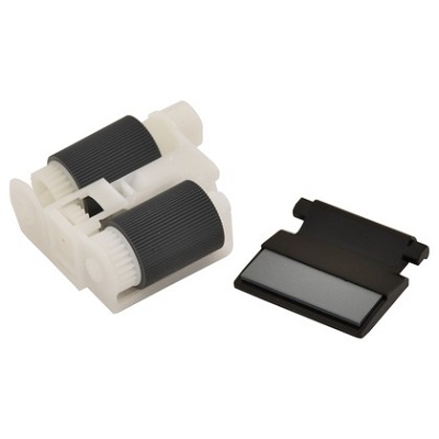
| Деталь: | PF KIT MP |
| Парткод: | D008GD001 |
| Цена: | 1 500 ₽ |
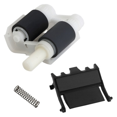
| Деталь: | PF KIT 1/2/3/4/5 |
| Парткод: | D008GE001 |
| Цена: | 2 100 ₽ |
| Деталь: | PAPER TRAY (SP) |
| Парткод: | D008XD001 |
| Деталь: | PAPER TRAY (SP) |
| Парткод: | D008XE001 |
| Деталь: | PAPER TRAY (SP) |
| Парткод: | D00551001 |
| Деталь: | PAPER TRAY (SP) |
| Парткод: | D00690001 |
| Деталь: | PAPER TRAY (SP) |
| Парткод: | D00690002 |
| Деталь: | IDLE GEAR Z18M10 |
| Парткод: | LY4242001 |
| Деталь: | IDLE GEAR 50 Z18M10 |
| Парткод: | LU9365001 |
| Деталь: | LIFT GEAR Z27M10 |
| Парткод: | LY4241001 |
| Деталь: | LIFT GEAR Z48M10 |
| Парткод: | LY4516001 |
| Деталь: | LIFT GEAR Z48M11 |
| Парткод: | LY4516001 |
| Деталь: | LIFT GEAR Z48M12 |
| Парткод: | LY4516001 |
| Деталь: | LIFT GEAR Z48M13 |
| Парткод: | LY4516001 |
| Деталь: | LIFT GEAR Z48M14 |
| Парткод: | LY4516001 |
| Деталь: | LIFT GEAR Z48M15 |
| Парткод: | LY4516001 |
| Деталь: | FRONT COVER ASSY |
| Парткод: | D003F2001 |
| Деталь: | FRONT COVER ASSY DL CHN DNH |
| Парткод: | D013FM001 |
| Деталь: | FRONT COVER ASSY |
| Парткод: | D008G1001 |
| Деталь: | FRONT COVER ASSY |
| Парткод: | D00056001 |
| Деталь: | FRONT COVER ASSY |
| Парткод: | D005LY001 |
| Деталь: | FRONT COVER ASSY |
| Парткод: | D006WJ001 |
| Деталь: | FRONT COVER ASSY |
| Парткод: | D003KL001 |
| Деталь: | FRONT COVER ASSY |
| Парткод: | D005NK001 |
| Деталь: | FRONT COVER ASSY |
| Парткод: | D005NL001 |
| Деталь: | FRONT COVER ASSY |
| Парткод: | D005Y9001 |
| Деталь: | FRONT COVER ASSY |
| Парткод: | D003KB001 |
| Деталь: | FRONT COVER ASSY |
| Парткод: | D003R8001 |
| Деталь: | FRONT COVER ASSY |
| Парткод: | D005MY001 |
| Деталь: | FRONT COVER ASSY |
| Парткод: | D005MZ001 |
| Деталь: | FRONT COVER ASSY |
| Парткод: | D004VF001 |
| Деталь: | FRONT COVER ASSY |
| Парткод: | D003R8002 |
| Деталь: | FRONT COVER ASSY |
| Парткод: | D004NP002 |
| Деталь: | FRONT COVER ASSY |
| Парткод: | D000DW001 |
| Деталь: | FRONT COVER ASSY |
| Парткод: | D0067A001 |
| Деталь: | FRONT COVER ASSY |
| Парткод: | D004NP003 |
| Деталь: | FRONT COVER ASSY |
| Парткод: | D00655001 |
| Деталь: | FRONT COVER ASSY |
| Парткод: | D006RN001 |
| Деталь: | FRONT COVER ASSY |
| Парткод: | D00653001 |
| Деталь: | FRONT COVER ASSY |
| Парткод: | D005YM001 |
| Деталь: | FRONT COVER ASSY |
| Парткод: | D006X6001 |
| Деталь: | FRONT COVER ASSY |
| Парткод: | D003KU001 |
| Деталь: | MP TRAY COVER ASSY SP |
| Парткод: | D008GF001 |
| Деталь: | MP TRAY COVER ASSY SP |
| Парткод: | D008GF002 |
| Деталь: | MP TRAY COVER ASSY SP |
| Парткод: | D008GG001 |
| Деталь: | MP TRAY COVER ASSY SP |
| Парткод: | D008GG002 |
| Деталь: | TOP COVER ASSY (SP) |
| Парткод: | D0091R001 |
| Деталь: | TOP COVER ASSY (SP) |
| Парткод: | D0091P001 |
| Деталь: | TOP COVER ASSY (SP) |
| Парткод: | D0091D001 |
| Деталь: | TOP COVER ASSY (SP) |
| Парткод: | D0091C001 |
| Деталь: | TOP COVER ASSY (SP) |
| Парткод: | D0167K001 |
| Деталь: | TOP COVER ASSY (SP) |
| Парткод: | D0091V001 |
| Деталь: | TOP COVER ASSY (SP) |
| Парткод: | D0091X001 |
| Деталь: | TOP COVER ASSY (SP) |
| Парткод: | D0091H001 |
| Деталь: | TOP COVER ASSY (SP) |
| Парткод: | D006TE001 |
| Деталь: | TOP COVER ASSY (SP) |
| Парткод: | D0091F001 |
| Деталь: | TOP COVER ASSY (SP) |
| Парткод: | D0091B001 |
| Деталь: | TOP COVER ASSY (SP) |
| Парткод: | D0091L001 |
| Деталь: | TOP COVER ASSY (SP) |
| Парткод: | D0091W001 |
| Деталь: | TOP COVER ASSY (SP) |
| Парткод: | D0091N001 |
| Деталь: | TOP COVER ASSY (SP) |
| Парткод: | D00A43001 |
| Деталь: | TOP COVER ASSY (SP) |
| Парткод: | D00920002 |
| Деталь: | TOP COVER ASSY (SP) |
| Парткод: | D006XD001 |
| Деталь: | TOP COVER ASSY (SP) |
| Парткод: | D011D2001 |
| Деталь: | TOP COVER ASSY (SP) |
| Парткод: | D0091J001 |
| Деталь: | TOP COVER ASSY 6450DW(SP) |
| Парткод: | D011D3001 |
| Деталь: | BACK COVER |
| Парткод: | D0021L001 |
| Деталь: | BACK COVER |
| Парткод: | D0005J001 |
| Деталь: | BACK COVER |
| Парткод: | D0005J002 |
| Деталь: | BACK COVER |
| Парткод: | D0014D001 |
| Деталь: | BACK COVER |
| Парткод: | D0014D002 |
| Деталь: | SIDE COVER R |
| Парткод: | D0021H001 |
| Деталь: | SIDE COVER R |
| Парткод: | D00300001 |
| Деталь: | SIDE COVER R |
| Парткод: | D0005U001 |
| Деталь: | SIDE COVER R |
| Парткод: | D001VF001 |
| Деталь: | SIDE COVER R |
| Парткод: | D001VF002 |
| Деталь: | SIDE COVER R |
| Парткод: | D000DT001 |
| Деталь: | SIDE COVER R |
| Парткод: | D000DT002 |
| Деталь: | SIDE COVER L |
| Парткод: | D0039X001 |
| Деталь: | SIDE COVER L |
| Парткод: | D0039K001 |
| Деталь: | SIDE COVER L |
| Парткод: | D0005Y001 |
| Деталь: | SIDE COVER L |
| Парткод: | D001VG001 |
| Деталь: | SIDE COVER L |
| Парткод: | D001VG002 |
| Деталь: | SIDE COVER L |
| Парткод: | D000DY001 |
| Деталь: | SIDE COVER L |
| Парткод: | D000DY002 |
| Деталь: | MP PAPER GUIDE ASSY |
| Парткод: | LY4174006 |
| Деталь: | MP PAPER GUIDE ASSY |
| Парткод: | LY4174007 |
| Деталь: | MP PAPER GUIDE ASSY |
| Парткод: | D001DW001 |
| Деталь: | MP PAPER GUIDE ASSY |
| Парткод: | D001DW002 |
| Деталь: | OUTER CHUTE |
| Парткод: | D00FF5001 |
| Деталь: | FUSER COVER |
| Парткод: | D005WD001 |
| Деталь: | LABEL REAR JAM 17X55 |
| Парткод: | D004VK001 |
| Деталь: | LABEL CAUTION FRONT 14X130 |
| Парткод: | D003JF001 |
| Деталь: | LABEL CAUTION FRONT 14X70 CHN |
| Парткод: | D00SBN001 |
| Деталь: | LABEL CAUTION FRONT 14X130US3 |
| Парткод: | D003JD001 |
| Деталь: | LABEL CAUTION FRONT 14X130 US2 |
| Парткод: | D003JC001 |
| Деталь: | LABEL CAUTION FRONT 14X130 US1 |
| Парткод: | D002RV001 |
| Деталь: | LABEL H CAUTION REAR 14X72 |
| Парткод: | LY4574001 |
| Деталь: | LABEL H CAUTION REAR 14X72 CHN |
| Парткод: | D00SBP001 |
| Деталь: | LABEL H CAUTION REAR 14X42 |
| Парткод: | D0030F001 |
| Деталь: | LABEL S CAUTION REAR 14X42 |
| Парткод: | D0030G001 |
| Деталь: | PAPER STOPPER |
| Парткод: | D0005D001 |
| Деталь: | PAPER STOPPER |
| Парткод: | D0005D002 |
| Деталь: | MP DAMPER SPRING |
| Парткод: | D000TH001 |
| Деталь: | MP DAMPER SPRING |
| Парткод: | D007PP001 |
| Деталь: | TOP COVER PRINTED ASSY |
| Парткод: | D004RZ001 |
| Деталь: | TOP COVER PRINTED ASSY |
| Парткод: | D004X1001 |
| Деталь: | TOP COVER PRINTED ASSY |
| Парткод: | D013FJ001 |
| Деталь: | TOP COVER PRINTED ASSY |
| Парткод: | D0005Z001 |
| Деталь: | TOP COVER PRINTED ASSY |
| Парткод: | D004X1002 |
| Деталь: | TOP COVER PRINTED ASSY |
| Парткод: | D0005Z002 |
| Деталь: | TOP COVER PRINTED ASSY |
| Парткод: | D0053B001 |
| Деталь: | TOP COVER PRINTED ASSY |
| Парткод: | D0053B002 |
| Деталь: | TOP COVER PRINTED ASSY |
| Парткод: | D001X6001 |
| Деталь: | LCD |
| Парткод: | A51299001 |
| Деталь: | PANEL PCB ASSY |
| Парткод: | D0000P001 |
| Деталь: | LCD SHEET |
| Парткод: | D003RS001 |
| Деталь: | LCD SHEET |
| Парткод: | D003RK001 |
| Деталь: | LCD SHEET |
| Парткод: | D003J6001 |
| Деталь: | LCD SHEET |
| Парткод: | D003FA001 |
| Деталь: | LCD SHEET |
| Парткод: | D0139D001 |
| Деталь: | LCD SHEET |
| Парткод: | D004R7001 |
| Деталь: | LCD SHEET |
| Парткод: | D003EU001 |
| Деталь: | LCD SHEET |
| Парткод: | D003KS001 |
| Деталь: | LCD SHEET |
| Парткод: | D0005R001 |
| Деталь: | LCD SHEET |
| Парткод: | D003KD001 |
| Деталь: | LCD SHEET |
| Парткод: | D001X5001 |
| Деталь: | LCD SHEET |
| Парткод: | D003LU001 |
| Деталь: | LCD SHEET |
| Парткод: | D003PY001 |
| Деталь: | STACK SENSOR PCB ASSY |
| Парткод: | D000CX001 |
| Деталь: | MX COVER ASSY |
| Парткод: | D001BE004 |
| Деталь: | MX COVER ASSY |
| Парткод: | D001BE002 |
| Деталь: | LCD PANEL ASSY |
| Парткод: | D009Y2001 |
| Деталь: | LCD PANEL ASSY |
| Парткод: | D0053F002 |
| Цена: | 3 200 ₽ |
| Деталь: | LCD PANEL ASSY |
| Парткод: | D001UB001 |
| Деталь: | LCD PANEL ASSY |
| Парткод: | D003L1001 |
| Деталь: | LCD PANEL ASSY |
| Парткод: | D00XXL001 |
| Деталь: | PANEL COVER CASE UPPER (SP) |
| Парткод: | D0077L002 |
| Деталь: | PANEL COVER CASE UPPER (SP) |
| Парткод: | D0077L001 |
| Деталь: | NFC PCB ASSY |
| Парткод: | D0000T002 |
| Деталь: | KEY PCB FLAT CABLE |
| Парткод: | D000D3001 |
| Деталь: | TONER LED PCB ASSY |
| Парткод: | D0000M001 |
| Деталь: | TONER LED PCB ASSY |
| Парткод: | D0000M002 |
| Деталь: | MAIN FAN |
| Парткод: | LY4367001 |
| Деталь: | MAIN FAN |
| Парткод: | D000BE001 |
| Деталь: | RELAY FRONT PCB ASSY |
| Парткод: | D0000N001 |
| Деталь: | MAIN HVPS FLAT CABLE |
| Парткод: | D0000U001 |
| Деталь: | T1 PAPER FEED SENSOR PCB ASSY |
| Парткод: | D0050V001 |
| Деталь: | FILTER |
| Парткод: | D00RH8001 |
| Деталь: | LT/TT CONNECTOR |
| Парткод: | LM9266001 |
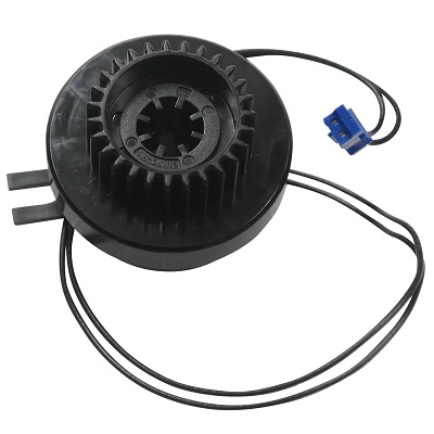
| Деталь: | REGISTRATION CLUTCH |
| Парткод: | LY4332001 |
| Цена: | 1 200 ₽ |
| Деталь: | T1 PICKUP CLUTCH |
| Парткод: | LY4335001 |
| Деталь: | PANEL PCB ASSY |
| Парткод: | D000CY001 |
| Деталь: | PANEL FLAT CABLE |
| Парткод: | D00515001 |
| Деталь: | MAIN FRAME L ASSY (SP) |
| Парткод: | D0091A001 |
| Деталь: | MAIN FRAME L ASSY (SP) |
| Парткод: | D00923001 |
| Деталь: | MAIN FRAME L ASSY (SP) |
| Парткод: | D0077C001 |
| Деталь: | MAIN FRAME L ASSY (SP) |
| Парткод: | D0091E001 |
| Деталь: | MAIN FRAME L ASSY (SP) |
| Парткод: | D0077H001 |
| Деталь: | MAIN FRAME L ASSY (SP) |
| Парткод: | D00925001 |
| Деталь: | MP SOLENOID |
| Парткод: | LU9352001 |
| Цена: | 850 ₽ |
| Деталь: | BACK COVER/DUPLEX TRAY SENSOR |
| Парткод: | D000YK001 |
| Цена: | 490 ₽ |
| Деталь: | TONER SENSOR PCB ASSY |
| Парткод: | D0000L001 |
| Цена: | 490 ₽ |
| Деталь: | EXTERNAL TEMPERATURE/HUMIDITY SENSOR |
| Парткод: | D0001C001 |
| Цена: | 800 ₽ |
| Деталь: | EJECT MOTOR |
| Парткод: | D00054001 |
| Цена: | 1 200 ₽ |
| Деталь: | INTERNAL TEMPERATURE SENSOR |
| Парткод: | D001BA001 |
| Цена: | 600 ₽ |
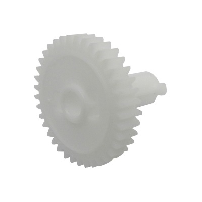
| Деталь: | DEVELOP JOINT GEAR 37 |
| Парткод: | LY4382001 |
| Цена: | 150 ₽ |
| Деталь: | DEVELOP CLUTCH 51R |
| Парткод: | LY4408001 |
| Деталь: | FUSER DRIVE GEAR 39 |
| Парткод: | LY4450001 |
| Цена: | 410 ₽ |
| Деталь: | PAPER FEED MOTOR |
| Парткод: | LY4378001 |
| Деталь: | PAPER FEED MOTOR |
| Парткод: | D000TC001 |
| Деталь: | DEVELOP JOINT |
| Парткод: | D001Y5001 |
| Деталь: | DEVELOP JOINT |
| Парткод: | LY4380001 |
| Цена: | 1 000 ₽ |
| Деталь: | MX CONNECTOR (MACHINE SIDE) |
| Парткод: | D000WD001 |
| Деталь: | LASER UNIT (SP) |
| Парткод: | D002ZC001 |
| Цена: | 11 800 ₽ |
| Деталь: | LASER UNIT (SP) |
| Парткод: | D002ZC00i |
| Деталь: | LASER UNIT (SP) |
| Парткод: | D002ZG001 |
| Цена: | 11 800 ₽ |
| Деталь: | LASER UNIT FLAT CABLE |
| Парткод: | D00010001 |
| Цена: | 200 ₽ |
| Деталь: | DUPLEX TRAY (SP) |
| Парткод: | D008UJ001 |
| Деталь: | DUPLEX TRAY (SP) |
| Парткод: | D008UG002 |
| Цена: | 4 100 ₽ |
| Деталь: | DUPLEX TRAY (SP) |
| Парткод: | D008UJ002 |
| Деталь: | DUPLEX TRAY (SP) |
| Парткод: | D008UK002 |
| Деталь: | DUPLEX TRAY (SP) |
| Парткод: | D008UH001 |
| Деталь: | DUPLEX TRAY (SP) |
| Парткод: | D008UG001 |
| Деталь: | DUPLEX TRAY (SP) |
| Парткод: | D008UK001 |
| Деталь: | FRONT COVER ASSY |
| Парткод: | D003F2001 |
| Деталь: | FRONT COVER ASSY DL CHN DNH |
| Парткод: | D013FM001 |
| Деталь: | FRONT COVER ASSY |
| Парткод: | D008G1001 |
| Деталь: | FRONT COVER ASSY |
| Парткод: | D00056001 |
| Деталь: | FRONT COVER ASSY |
| Парткод: | D005LY001 |
| Деталь: | FRONT COVER ASSY |
| Парткод: | D006WJ001 |
| Деталь: | FRONT COVER ASSY |
| Парткод: | D003KL001 |
| Деталь: | FRONT COVER ASSY |
| Парткод: | D005NK001 |
| Деталь: | FRONT COVER ASSY |
| Парткод: | D005NL001 |
| Деталь: | FRONT COVER ASSY |
| Парткод: | D005Y9001 |
| Деталь: | FRONT COVER ASSY |
| Парткод: | D003KB001 |
| Деталь: | FRONT COVER ASSY |
| Парткод: | D003R8001 |
| Деталь: | FRONT COVER ASSY |
| Парткод: | D005MY001 |
| Деталь: | FRONT COVER ASSY |
| Парткод: | D005MZ001 |
| Деталь: | FRONT COVER ASSY |
| Парткод: | D004VF001 |
| Деталь: | FRONT COVER ASSY |
| Парткод: | D003R8002 |
| Деталь: | FRONT COVER ASSY |
| Парткод: | D004NP002 |
| Деталь: | FRONT COVER ASSY |
| Парткод: | D000DW001 |
| Деталь: | FRONT COVER ASSY |
| Парткод: | D0067A001 |
| Деталь: | FRONT COVER ASSY |
| Парткод: | D004NP003 |
| Деталь: | FRONT COVER ASSY |
| Парткод: | D00655001 |
| Деталь: | FRONT COVER ASSY |
| Парткод: | D006RN001 |
| Деталь: | FRONT COVER ASSY |
| Парткод: | D00653001 |
| Деталь: | FRONT COVER ASSY |
| Парткод: | D005YM001 |
| Деталь: | FRONT COVER ASSY |
| Парткод: | D006X6001 |
| Деталь: | FRONT COVER ASSY |
| Парткод: | D003KU001 |
| Деталь: | MP TRAY COVER ASSY SP |
| Парткод: | D008GF001 |
| Деталь: | MP TRAY COVER ASSY SP |
| Парткод: | D008GF002 |
| Деталь: | MP TRAY COVER ASSY SP |
| Парткод: | D008GG001 |
| Деталь: | MP TRAY COVER ASSY SP |
| Парткод: | D008GG002 |
| Деталь: | TOP COVER ASSY (SP) |
| Парткод: | D0091X001 |
| Деталь: | TOP COVER ASSY (SP) |
| Парткод: | D0091H001 |
| Деталь: | TOP COVER ASSY (SP) |
| Парткод: | D006TE001 |
| Деталь: | TOP COVER ASSY (SP) |
| Парткод: | D0091F001 |
| Деталь: | TOP COVER ASSY (SP) |
| Парткод: | D0091B001 |
| Деталь: | TOP COVER ASSY (SP) |
| Парткод: | D0091L001 |
| Деталь: | TOP COVER ASSY (SP) |
| Парткод: | D0091W001 |
| Деталь: | TOP COVER ASSY (SP) |
| Парткод: | D0091N001 |
| Деталь: | TOP COVER ASSY (SP) |
| Парткод: | D00A43001 |
| Деталь: | TOP COVER ASSY (SP) |
| Парткод: | D00920002 |
| Деталь: | TOP COVER ASSY (SP) |
| Парткод: | D006XD001 |
| Деталь: | TOP COVER ASSY (SP) |
| Парткод: | D011D2001 |
| Деталь: | TOP COVER ASSY (SP) |
| Парткод: | D0091J001 |
| Деталь: | TOP COVER ASSY 6450DW(SP) |
| Парткод: | D011D3001 |
| Деталь: | TOP COVER ASSY (SP) |
| Парткод: | D0091R001 |
| Деталь: | TOP COVER ASSY (SP) |
| Парткод: | D0091P001 |
| Деталь: | TOP COVER ASSY (SP) |
| Парткод: | D0091D001 |
| Деталь: | TOP COVER ASSY (SP) |
| Парткод: | D0091C001 |
| Деталь: | TOP COVER ASSY (SP) |
| Парткод: | D0167K001 |
| Деталь: | TOP COVER ASSY (SP) |
| Парткод: | D0091V001 |
| Деталь: | BACK COVER |
| Парткод: | D0021L001 |
| Деталь: | BACK COVER |
| Парткод: | D0005J001 |
| Деталь: | BACK COVER |
| Парткод: | D0005J002 |
| Деталь: | BACK COVER |
| Парткод: | D0014D001 |
| Деталь: | BACK COVER |
| Парткод: | D0014D002 |
| Деталь: | SIDE COVER R |
| Парткод: | D0021H001 |
| Деталь: | SIDE COVER R |
| Парткод: | D00300001 |
| Деталь: | SIDE COVER R |
| Парткод: | D0005U001 |
| Деталь: | SIDE COVER R |
| Парткод: | D001VF001 |
| Деталь: | SIDE COVER R |
| Парткод: | D001VF002 |
| Деталь: | SIDE COVER R |
| Парткод: | D000DT001 |
| Деталь: | SIDE COVER R |
| Парткод: | D000DT002 |
| Деталь: | SIDE COVER L |
| Парткод: | D0039X001 |
| Деталь: | SIDE COVER L |
| Парткод: | D0039K001 |
| Деталь: | SIDE COVER L |
| Парткод: | D0005Y001 |
| Деталь: | SIDE COVER L |
| Парткод: | D001VG001 |
| Деталь: | SIDE COVER L |
| Парткод: | D001VG002 |
| Деталь: | SIDE COVER L |
| Парткод: | D000DY001 |
| Деталь: | SIDE COVER L |
| Парткод: | D000DY002 |
| Деталь: | MP PAPER GUIDE ASSY |
| Парткод: | LY4174006 |
| Деталь: | MP PAPER GUIDE ASSY |
| Парткод: | LY4174007 |
| Деталь: | MP PAPER GUIDE ASSY |
| Парткод: | D001DW001 |
| Деталь: | MP PAPER GUIDE ASSY |
| Парткод: | D001DW002 |
| Деталь: | OUTER CHUTE |
| Парткод: | D00FF5001 |
| Деталь: | FUSER COVER |
| Парткод: | D005WD001 |
| Деталь: | LABEL REAR JAM 17X55 |
| Парткод: | D004VK001 |
| Деталь: | LABEL CAUTION FRONT 14X130 |
| Парткод: | D003JF001 |
| Деталь: | LABEL CAUTION FRONT 14X130 US2 |
| Парткод: | D003JC001 |
| Деталь: | LABEL CAUTION FRONT 14X130 US1 |
| Парткод: | D002RV001 |
| Деталь: | LABEL CAUTION FRONT 14X70 CHN |
| Парткод: | D00SBN001 |
| Деталь: | LABEL CAUTION FRONT 14X130US3 |
| Парткод: | D003JD001 |
| Деталь: | LABEL H CAUTION REAR 14X72 |
| Парткод: | LY4574001 |
| Деталь: | LABEL H CAUTION REAR 14X72 CHN |
| Парткод: | D00SBP001 |
| Деталь: | LABEL H CAUTION REAR 14X42 |
| Парткод: | D0030F001 |
| Деталь: | LABEL S CAUTION REAR 14X42 |
| Парткод: | D0030G001 |
| Деталь: | PAPER STOPPER |
| Парткод: | D0005D001 |
| Деталь: | PAPER STOPPER |
| Парткод: | D0005D002 |
| Деталь: | MP DAMPER SPRING |
| Парткод: | D000TH001 |
| Деталь: | MP DAMPER SPRING |
| Парткод: | D007PP001 |
| Деталь: | TOP COVER PRINTED ASSY |
| Парткод: | D004RZ001 |
| Деталь: | TOP COVER PRINTED ASSY |
| Парткод: | D004X1001 |
| Деталь: | TOP COVER PRINTED ASSY |
| Парткод: | D013FJ001 |
| Деталь: | TOP COVER PRINTED ASSY |
| Парткод: | D0005Z001 |
| Деталь: | TOP COVER PRINTED ASSY |
| Парткод: | D004X1002 |
| Деталь: | TOP COVER PRINTED ASSY |
| Парткод: | D0005Z002 |
| Деталь: | TOP COVER PRINTED ASSY |
| Парткод: | D0053B001 |
| Деталь: | TOP COVER PRINTED ASSY |
| Парткод: | D0053B002 |
| Деталь: | TOP COVER PRINTED ASSY |
| Парткод: | D001X6001 |
| Деталь: | LCD |
| Парткод: | A51299001 |
| Деталь: | PANEL PCB ASSY |
| Парткод: | D0000P001 |
| Деталь: | LCD SHEET |
| Парткод: | D003RS001 |
| Деталь: | LCD SHEET |
| Парткод: | D003RK001 |
| Деталь: | LCD SHEET |
| Парткод: | D003J6001 |
| Деталь: | LCD SHEET |
| Парткод: | D003FA001 |
| Деталь: | LCD SHEET |
| Парткод: | D0139D001 |
| Деталь: | LCD SHEET |
| Парткод: | D004R7001 |
| Деталь: | LCD SHEET |
| Парткод: | D003EU001 |
| Деталь: | LCD SHEET |
| Парткод: | D003KS001 |
| Деталь: | LCD SHEET |
| Парткод: | D0005R001 |
| Деталь: | LCD SHEET |
| Парткод: | D003KD001 |
| Деталь: | LCD SHEET |
| Парткод: | D001X5001 |
| Деталь: | LCD SHEET |
| Парткод: | D003LU001 |
| Деталь: | LCD SHEET |
| Парткод: | D003PY001 |
| Деталь: | STACK SENSOR PCB ASSY |
| Парткод: | D000CX001 |
| Деталь: | MX COVER ASSY |
| Парткод: | D001BE004 |
| Деталь: | MX COVER ASSY |
| Парткод: | D001BE002 |
| Деталь: | LCD PANEL ASSY |
| Парткод: | D009Y2001 |
| Деталь: | LCD PANEL ASSY |
| Парткод: | D0053F002 |
| Цена: | 3 200 ₽ |
| Деталь: | LCD PANEL ASSY |
| Парткод: | D001UB001 |
| Деталь: | LCD PANEL ASSY |
| Парткод: | D003L1001 |
| Деталь: | LCD PANEL ASSY |
| Парткод: | D00XXL001 |
| Деталь: | PANEL COVER CASE UPPER (SP) |
| Парткод: | D0077L002 |
| Деталь: | PANEL COVER CASE UPPER (SP) |
| Парткод: | D0077L001 |
| Деталь: | NFC PCB ASSY |
| Парткод: | D0000T002 |
| Деталь: | KEY PCB FLAT CABLE |
| Парткод: | D000D3001 |
| Деталь: | FUSER UNIT (SP) |
| Парткод: | D008AE001 |
| Деталь: | FUSER UNIT (SP) |
| Парткод: | D008AL001 |
| Деталь: | FUSER UNIT (SP) |
| Парткод: | D005WR001 |
| Деталь: | FUSER UNIT (SP) |
| Парткод: | D008AH001 |
| Деталь: | FUSER UNIT (SP) |
| Парткод: | D008AK001 |
| Деталь: | FUSER UNIT (SP) |
| Парткод: | D00V9L001 |
| Деталь: | FUSER UNIT (SP) |
| Парткод: | D008AM001 |
| Деталь: | FUSER UNIT (SP) |
| Парткод: | D0096U001 |
| Цена: | 20 600 ₽ |
Коды ошибок
0102
0201
0203
0300
0305
0401
0405
0501
0502
0503
0504
0505
0506
0508
050A
050B
050C
0800
0900
0A02
0B01
0B02
1701
1801
1802
1803
1808
1901
1A01
1B01
1F00
3801
4000
4200
4500
4600
4B01
4C01
4F01
5001
5002
5003
5004
5005
5006
6001
6004
6101
6200
6801
6901
6902
6A00
6D00
6F00
7000
7100
7200
7301
7302
7401
7402
7501
7502
7601
7602
7701
7702
7800
7B01
7B02
7B03
7B04
7B05
7F00
8501
8502
8503
8504
8505
8506
8507
8508
8701
8702
8708
8709
870A
870B
870C
870D
870E
870F
8808
8809
8903
8904
8A01
8B01
9001
9002
9003
9004
9005
9006
9201
9202
9203
9204
9205
9206
9301
9302
9303
9304
9305
9306
9309
9400
9701
9702
9703
9704
9705
9706
C001
C002
C003
C004
C100
C700
C800
D800
E000
E100
E500
E600
E701
E702
E900
EC00
F900
Описание
| Error code: | 0102 |
| Display: | MAINTENANCE CALL 0102 |
| Description: | Even though the machine carries out the regular movement, the output of Head Lock Sensor does not reach the expected value. |
| Causes: | Head Lock Sensor does not work correctly or is broken. |
| Remedy: | Head Lock Sensor replacement Check the mechanical backlash or loose with the scan axis related parts. |
| Error code: | 0201 |
| Display: | Print Unable 02 Turn the power off and then back on again. |
| Description: | Head 2 is abnormally hot. Head 2 temperature has reached 58°C and above. |
| Causes: | Thermistor (Head) has a problem. Flexible Cable has short circuitted or cut-line. |
| Remedy: | Check Flexible Cable connection around Head Head replacement |
| Error code: | 0203 |
| Description: | Head 4 is abnormally hot. Head 4 temperature has reached 58°C and above. |
| Causes: | Thermistor (Head) has a problem. Flexible Cable has short circuitted or cut-line. |
| Remedy: | Check Flexible Cable connection around Head Head replacement |
| Error code: | 0300 |
| Display: | POLYGON MOTOR |
| Description: | Polygon motor malfunction |
| Causes: | • The polygon motor does not rotate evenly even after the lapse of a given period of time after it has been started. • The motor lock signal remains HIGH for a given period of consecutive time while the polygon motor is being rotated. |
| Remedy: | 1 Check the cable and connector for proper connection and correct as necessary. - - 2 Change PH unit. - - 3 Change PRCB. - - |
| Error code: | 0305 |
| Description: | ROM Checksum Failure |
| Remedy: | Replace the system board. |
| Error code: | 0401 |
| Display: | Print Unable 04 Turn the power off and then back on again. |
| Description: | BD sensor 1 damaged. |
| Remedy: | 1 Connection failure of the polygon motor harness Reconnect the polygon motor harness. 2 Laser unit failure Replace the laser unit. 3 Main PCB failure Replace the main PCB ASSY. |
| Error code: | 0405 |
| Description: | Cannot detect the synchronized signal of the polygon motor for the laser unit (first time). |
| Remedy: | 1 Connection failure of the laser unit flat cable Reconnect the laser unit flat cable. 2 Laser unit flat cable failure Replace the laser unit flat cable. 3 Laser unit failure Replace the laser unit. 4 Main PCB failure Replace the main PCB ASSY. |
| Error code: | 0501 |
| Display: | FUSER ERROR |
| Description: | Fusing Pressure Roller warm-up failure • The Fusing Pressure Roller Thermistor/1 (TH2) fails to raise a given degree of temperature even after the lapse of a given period of time after the Fusing Pressure Heater Lamp (H3) is turned ON. • The detected temperature of the Fusing Pressure Roller Thermistor/1 (TH2) is lower for a given level of degree than one of the Heating Roller Thermistor/1 (TH1) after the Front Door is opened or closed, the Main Power Switch is turned ON or TROUBLE RESET is implemented. |
| Causes: | 1 Connection failure of the center or side thermistor harness of the fuser unit 2 Connection failure of the heater harness of the fuser unit 3 Harness connection failure of the eject sensor PCB 4 Harness connection failure of the low-voltage power supply PCB 5 Eject sensor PCB failure 6 Fuser unit failure 7 Low-voltage power supply PCB failure 8 Main PCB failure |
| Remedy: | 1 Check the Fusing Unit for correct installation (whether it is secured in position). 2 Check the Fusing Unit, PWB-M and PU1 for proper connection and correct or change as necessary. 3 Change Fusing Unit. 4 Change PWB-M. 5 Change PU1. |
| Error code: | 0502 |
| Display: | Thermistor failure CODE (0502) Turn power off, on |
| Description: | 0502 Thermistor Failure, 0510 Fuser Failure, and 0520 Fuser Failure 0502 Thermistor Failure The temperature detected by the thermistor does not reach an expected level after the warm-up cycle starts. |
| Causes: | • Fuser, PL4.0.13 • Engine Control Board, PL13.0.20 • Power Supply, PL13.0.17 |
| Remedy: | 1 Check that the Fuser is installed correctly. Does the problem persist? Go to step 2. Complete. 2 Check the Engine Control Board connectors P/J2, P/J3, and P/J6. Are the connectors seated properly? Go to step 3 Reseat the connectors. If the problem persists, go to step 3. 3 Check the Low Voltage Power Supply connectors CN3, CN5, and CN7. Are the connectors seated properly? Go to step 4. Reseat the connectors. If the problem persists, go to step 4. 4 Replace the Fuser (8-9). Does the problem persist? Go to step 5. Complete. 5 Replace the Engine Control Board. Does the problem persist? Go to step 6. Complete. 6 Replace the Power Supply. Complete. |
| Error code: | 0503 |
| Display: | TERMISTOR2 |
| Description: | Thermistor resistance failure |
| Causes: | • The difference between the temperature detected by thermistor/1 and that detected by thermistor/2 exceeds a predetermined value. |
| Remedy: | 1 Change fuser unit. - - 2 For C110: 1. Main switch is turned ON. 2. Open the top cover. 3. Press the following keys in this order. ROTATE TONER key -ATTENTION key - ATTENTION key - ROTATE TONER key. 4. Main switch is turned OFF/ON. For C130n: 1. Main switch is turned ON. 2. Execute [SERVICE MENU] - [FUSER UNLOCK]. See P.103 - - 3 Change PRCB. - - 4 Change DCPU. - - |
| Error code: | 0504 |
| Display: | Print Unable 05 Turn the power off and then back on again. |
| Description: | After the center thermistor of the fuser unit was normally heated, it detected a temperature lower than the specified value. |
| Causes: | 1 Connection failure of the center or side thermistor harness of the fuser unit 2 Connection failure of the heater harness of the fuser unit 3 Harness connection failure of the eject sensor PCB 4 Harness connection failure of the low-voltage power supply PCB 5 Eject sensor PCB failure 6 Fuser unit failure 7 Low-voltage power supply PCB failure 8 Main PCB failure |
| Remedy: | < User Check > - Turn OFF the power switch. After several seconds, turn ON the power again and check that this error is reset. 1 Connection failure of the center or side thermistor harness of the fuser unit Reconnect the harness of the center thermistor or side thermistor of the fuser unit. 2 Connection failure of the heater harness of the fuser unit Reconnect the heater harness of the fuser unit. 3 Connection failure of the eject sensor PCB harness Reconnect the eject sensor PCB harness. 4 Connection failure of the low-voltage power supply PCB harness Reconnect the low-voltage power supply PCB harness. 5 Eject sensor PCB failure Replace the eject sensor PCB ASSY. 6 Fuser unit failure Replace the fuser unit. 7 Low-voltage power supply PCB failure Replace the low-voltage power supply PCB unit. 8 Main PCB failure Replace the main PCB ASSY. |
| Error code: | 0505 |
| Display: | Print Unable 05 Turn the power off and then back on again. |
| Description: | The center thermistor of the fuser unit detected a temperature rise greater than the specified value within a set period of time. |
| Causes: | 1 Connection failure of the center or side thermistor harness of the fuser unit 2 Connection failure of the heater harness of the fuser unit 3 Harness connection failure of the eject sensor PCB 4 Harness connection failure of the low-voltage power supply PCB 5 Eject sensor PCB failure 6 Fuser unit failure 7 Low-voltage power supply PCB failure 8 Main PCB failure |
| Remedy: | < User Check > - Turn OFF the power switch. After several seconds, turn ON the power again and check that this error is reset. 1 Connection failure of the center or side thermistor harness of the fuser unit Reconnect the harness of the center thermistor or side thermistor of the fuser unit. 2 Connection failure of the heater harness of the fuser unit Reconnect the heater harness of the fuser unit. 3 Connection failure of the eject sensor PCB harness Reconnect the eject sensor PCB harness. 4 Connection failure of the low-voltage power supply PCB harness Reconnect the low-voltage power supply PCB harness. 5 Eject sensor PCB failure Replace the eject sensor PCB ASSY. 6 Fuser unit failure Replace the fuser unit. 7 Low-voltage power supply PCB failure Replace the low-voltage power supply PCB unit. 8 Main PCB failure Replace the main PCB ASSY. |
| Error code: | 0506 |
| Display: | Print Unable 05 Turn the power off and then back on again. |
| Description: | The center thermistor of the fuser unit detected a temperature fall greater than the specified value within a set period of time. |
| Causes: | 1 Connection failure of the center or side thermistor harness of the fuser unit 2 Connection failure of the heater harness of the fuser unit 3 Harness connection failure of the eject sensor PCB 4 Harness connection failure of the low-voltage power supply PCB 5 Eject sensor PCB failure 6 Fuser unit failure 7 Low-voltage power supply PCB failure 8 Main PCB failure |
| Remedy: | < User Check > - Turn OFF the power switch. After several seconds, turn ON the power again and check that this error is reset. 1 Connection failure of the center or side thermistor harness of the fuser unit Reconnect the harness of the center thermistor or side thermistor of the fuser unit. 2 Connection failure of the heater harness of the fuser unit Reconnect the heater harness of the fuser unit. 3 Connection failure of the eject sensor PCB harness Reconnect the eject sensor PCB harness. 4 Connection failure of the low-voltage power supply PCB harness Reconnect the low-voltage power supply PCB harness. 5 Eject sensor PCB failure Replace the eject sensor PCB ASSY. 6 Fuser unit failure Replace the fuser unit. 7 Low-voltage power supply PCB failure Replace the low-voltage power supply PCB unit. 8 Main PCB failure Replace the main PCB ASSY. |
| Error code: | 0508 |
| Display: | Print Unable 05 Turn the power off and then back on again. |
| Description: | The side thermistor of the fuser unit did not detect a temperature rise when the heater was ON. |
| Remedy: | 1 Connection failure of the center or side thermistor harness of the fuser unit Reconnect the center or side thermistor harness of the fuser unit. 2 Connection failure of the fuser unit heater harness Reconnect the fuser unit heater harness. 3 Connection failure of the eject sensor harness Reconnect the eject sensor harness. 4 Connection failure of the lowvoltage power supply harness Reconnect the low-voltage power supply harness. 5 Eject sensor PCB failure Replace the eject sensor PCB ASSY. 6 Fuser unit failure Replace the fuser unit. 7 Low-voltage power supply PCB failure Replace the low-voltage power supply PCB ASSY. 8 Main PCB failure Replace the main PCB ASSY. |
| Error code: | 050A |
| Display: | Print Unable 05 Turn the power off and then back on again. |
| Description: | The center thermistor or side thermistor of the fuser unit detected some temperature error in the hardware. |
| Causes: | 1 Connection failure of the center or side thermistor harness of the fuser unit 2 Connection failure of the heater harness of the fuser unit 3 Harness connection failure of the eject sensor PCB 4 Harness connection failure of the low-voltage power supply PCB 5 Eject sensor PCB failure 6 Fuser unit failure 7 Low-voltage power supply PCB failure 8 Main PCB failure |
| Remedy: | < User Check > - Turn OFF the power switch. After several seconds, turn ON the power again and check that this error is reset. 1 Connection failure of the center or side thermistor harness of the fuser unit Reconnect the harness of the center thermistor or side thermistor of the fuser unit. 2 Connection failure of the heater harness of the fuser unit Reconnect the heater harness of the fuser unit. 3 Connection failure of the eject sensor PCB harness Reconnect the eject sensor PCB harness. 4 Connection failure of the low-voltage power supply PCB harness Reconnect the low-voltage power supply PCB harness. 5 Eject sensor PCB failure Replace the eject sensor PCB ASSY. 6 Fuser unit failure Replace the fuser unit. 7 Low-voltage power supply PCB failure Replace the low-voltage power supply PCB unit. 8 Main PCB failure Replace the main PCB ASSY. |
| Error code: | 050B |
| Display: | Print Unable 05 Turn the power off and then back on again. |
| Description: | When the temperature of the center thermistor of the fuser unit is lower than the idle temperature, the side thermistor of the fuser unit detected a temperature higher than the specified value. |
| Causes: | 1 Connection failure of the center or side thermistor harness of the fuser unit 2 Connection failure of the heater harness of the fuser unit 3 Harness connection failure of the eject sensor PCB 4 Harness connection failure of the low-voltage power supply PCB 5 Eject sensor PCB failure 6 Fuser unit failure 7 Low-voltage power supply PCB failure 8 Main PCB failure |
| Remedy: | < User Check > - Turn OFF the power switch. After several seconds, turn ON the power again and check that this error is reset. 1 Connection failure of the center or side thermistor harness of the fuser unit Reconnect the harness of the center thermistor or side thermistor of the fuser unit. 2 Connection failure of the heater harness of the fuser unit Reconnect the heater harness of the fuser unit. 3 Connection failure of the eject sensor PCB harness Reconnect the eject sensor PCB harness. 4 Connection failure of the low-voltage power supply PCB harness Reconnect the low-voltage power supply PCB harness. 5 Eject sensor PCB failure Replace the eject sensor PCB ASSY. 6 Fuser unit failure Replace the fuser unit. 7 Low-voltage power supply PCB failure Replace the low-voltage power supply PCB unit. 8 Main PCB failure Replace the main PCB ASSY. |
| Error code: | 050C |
| Display: | Print Unable 05 Turn the power off and then back on again. |
| Description: | When the temperature of the center thermistor of the fuser unit is higher than the idle temperature, the side thermistor of the fuser unit detected a temperature lower than the specified value. |
| Causes: | 1 Connection failure of the center or side thermistor harness of the fuser unit 2 Connection failure of the heater harness of the fuser unit 3 Harness connection failure of the eject sensor PCB 4 Harness connection failure of the low-voltage power supply PCB 5 Eject sensor PCB failure 6 Fuser unit failure 7 Low-voltage power supply PCB failure 8 Main PCB failure |
| Remedy: | < User Check > - Turn OFF the power switch. After several seconds, turn ON the power again and check that this error is reset. 1 Connection failure of the center or side thermistor harness of the fuser unit Reconnect the harness of the center thermistor or side thermistor of the fuser unit. 2 Connection failure of the heater harness of the fuser unit Reconnect the heater harness of the fuser unit. 3 Connection failure of the eject sensor PCB harness Reconnect the eject sensor PCB harness. 4 Connection failure of the low-voltage power supply PCB harness Reconnect the low-voltage power supply PCB harness. 5 Eject sensor PCB failure Replace the eject sensor PCB ASSY. 6 Fuser unit failure Replace the fuser unit. 7 Low-voltage power supply PCB failure Replace the low-voltage power supply PCB unit. 8 Main PCB failure Replace the main PCB ASSY. |
| Error code: | 0800 |
| Display: | Print Unable 08 Turn the power off and then back on again. |
| Description: | Image processing error JAM010X is detected twice. |
| Causes: | Defective main PWB. |
| Remedy: | Main PWB Replace the main PWB. |
| Error code: | 0900 |
| Display: | Print Unable 09 Turn the power off and then back on again. |
| Description: | FAX software incompatible detection error Incompatible FAX control PWB is installed. |
| Causes: | Defective FAX software. Defective FAX control PWB. |
| Remedy: | Defective FAX software. Install the fax software. Defective FAX control PWB. Replace the fax control PWB and check for correct operation. |
| Error code: | 0A02 |
| Display: | Print Unable 0A Turn the power off and then back on again. |
| Description: | The fuser fan failure was detected. |
| Causes: | 1 Harness connection failure of the main fan 2 Harness connection failure of the high-voltage power supply PCB 3 Harness connection failure between the low-voltage power supply PCB and main PCB 4 Main fan failure 5 Low-voltage power supply PCB failure 6 High-voltage power supply PCB failure 7 Main PCB failure |
| Remedy: | 1 Connection failure of the fuser fan harness Reconnect the fuser fan harness. 2 Connection failure of the high-voltage power supply PCB harness Reconnect the high-voltage power supply PCB harness. 3 Fuser fan failure Replace the fuser fan. 4 Low-voltage power supply PCB failure Replace the low-voltage power supply PCB unit. 5 High-voltage power supply PCB failure Replace the high-voltage power supply PCB ASSY. 6 Main PCB failure Replace the main PCB ASSY. |
| Error code: | 0B01 |
| Display: | Print Unable 0B Turn the power off and then back on again. |
| Description: | Error occurred in the high-voltage power supply PCB ASSY while the machine is in operation. |
| Causes: | 1 Harness connection failure of the high-voltage power supply PCB 2 High-voltage power supply PCB failure 3 Main PCB failure |
| Remedy: | < User Check > - Replace the drum unit. 1 Connection failure of the high-voltage power supply PCB harness Reconnect the high-voltage power supply PCB harness. 2 High-voltage power supply PCB failure Replace the high-voltage power supply PCB ASSY. 3 Main PCB failure Replace the main PCB ASSY. |
| Error code: | 0B02 |
| Display: | Print Unable 0B Turn the power off and then back on again. |
| Description: | Error occurred in the high-voltage power supply PCB ASSY in the ready state. |
| Causes: | 1 Harness connection failure of the high-voltage power supply PCB 2 High-voltage power supply PCB failure 3 Main PCB failure |
| Remedy: | < User Check > - Replace the drum unit. 1 Connection failure of the high-voltage power supply PCB harness Reconnect the high-voltage power supply PCB harness. 2 High-voltage power supply PCB failure Replace the high-voltage power supply PCB ASSY. 3 Main PCB failure Replace the main PCB ASSY. |
| Error code: | 1701 |
| Description: | SGRaster general error: false number of parameters (support number: 3311/alarm code: -) |
| Causes: | The number of print data parameters is incorrect. |
| Remedy: | Check the print result. When using print program such as RIP (Raster Image Processor), ask the manufacturer of the print program. |
| Error code: | 1801 |
| Description: | AID communication error |
| Causes: | An error occurs during AID communication check. • Connection failure of the AID Board. • AID Board failure |
| Remedy: | Replace the AID Board. |
| Error code: | 1802 |
| Description: | HP-GL/2 command unsupported (support number: 3302, alarm code: 0077) |
| Causes: | The printer detects unsupported HP-GL/2 command. |
| Remedy: | Check the data to print. |
| Error code: | 1803 |
| Description: | Overflow during processing HP-GL/2 data - (2) (support number: 3303, alarm code: 0074) |
| Causes: | Memory overflows during processing HP-GL/2 data. |
| Remedy: | • Decrease drawing data. • Transform the data to HP RTL data which can be operated on-the-fly.* *On-The-Fly : the mechanism of sending data to the printer from the top of the papers in sequence. The software that can create HP-GL/2 has an optional setting to select On-The- Fly. Selecting this option can reduce memory consumption. |
| Error code: | 1808 |
| Description: | Fixing Delivery Delay JAM 1 |
| Causes: | Fixing Delivery Sensor Delay |
| Remedy: | PS13 Drum Area to Fixing Area |
| Error code: | 1901 |
| Description: | Fixing Delivery Delay Jam |
| Causes: | Fixing Delivery Sensor SR3 |
| Remedy: | Pickup Cassette of the host machine |
| Error code: | 1A01 |
| Description: | A communication error occurred between the ASIC and MX control PCB in the engine. |
| Remedy: | 1 Connection failure of the MX control PCB harness Reconnect the MX control PCB harness. 2 MX connector failure (machine side or MX side) Replace the MX connector of the machine side or MX side. 3 MX control PCB failure Replace the MX control PCB. 4 Main PCB failure Replace the main PCB ASSY. |
| Error code: | 1B01 |
| Description: | Detected an MX motor failure. |
| Remedy: | 1 Connection failure of the MX motor harness Reconnect the MX motor harness. 2 MX connector failure (machine side or MX side) Replace the MX connector of the machine side or MX side. 3 MX motor failure Replace the MX motor. 4 MX control PCB failure Replace the MX control PCB. 5 Main PCB failure Replace the main PCB ASSY. |
| Error code: | 1F00 |
| Description: | When the TT was connected, TT balance sensor L/R wasn`t connected properly. |
| Remedy: | 1 Connection failure of the TT balance sensor L/R harness. Reconnect the TT balance sensor L/R harness or relay connector harness. 2 TT balance sensor L/R attachment failure Reattach the TT balance sensor L/R. 3 LT/TT connector failure (machine side or TT side) Replace the LT/TT connector of the machine side or TT side. 4 TT balance sensor L/R failure Replace the TT balance sensor L/R. 5 TT control PCB failure Replace the TT control PCB ASSY. 6 Main PCB failure Replace the main PCB ASSY. |
| Error code: | 3801 |
| Display: | Print Unable 38 Turn the power off and then back on again. |
| Description: | Temperature error occurred in the external temperature/humidity sensor. |
| Causes: | 1 External temperature/humidity sensor harness connection failure 2 External temperature/humidity sensor failure 3 Main PCB failure |
| Remedy: | 1 Connection failure of the high-voltage power supply PCB harness Reconnect the high-voltage power supply PCB harness. 2 External temperature/humidity sensor failure Replace the high-voltage power supply PCB ASSY. 3 Main PCB failure Replace the main PCB ASSY. |
| Error code: | 4000 |
| Display: | Supplies Drum End Soon. |
| Description: | Command Communication Error. |
| Causes: | The communication error occurs when the IC4 or IC22 on the Main Board is broken. And it causes the Motor Error. |
| Remedy: | Replace the Main Board. |
| Error code: | 4200 |
| Display: | Supplies Replace Drum |
| Description: | BD steady-state error The BD signal is not detected. |
| Causes: | APC PWB (LSU). Main/Engine PWB. |
| Remedy: | APC PWB (LSU) 1. Confirm that the FCC wiring connector is not distorted and connect the FCC wiring all the way in. Laser scanner unit and main/engine PWB (YC2010) 2. If the FCC wiring is disconnected, shorted or grounded, replace the FCC wiring. 3. Replace the laser scanner unit. Main/Engine PWB 1. Check the main/engine software and upgrade to the latest, if necessary. 2. Replace the main/engine PWB. |
| Error code: | 4500 |
| Display: | Maintenance Replace Fuser |
| Description: | Number of used pages for the fuser unit has reached the upper limit. (Printing is not stopped.j |
| Causes: | 1 Main PCB failure if the error code remains after replacing with a new fuser unit and resetting the fuser unit counter |
| Remedy: | 1 The fuser unit is at the end of life Replace the fuser unit. After replacing the fuser unit, refer to (Function code 88), and reset the fuser unit counter. 2 Main PCB failure if the error code remains after replacing with a new fuser unit and resetting the fuser unit counter Replace the main PCB ASSY. |
| Error code: | 4600 |
| Display: | Maintenance Replace Laser |
| Description: | LSU cleaning motor error After LSU cleaning motor is driven, the ready signal does not turn to L within 2 s. After LSU cleaning motor is stabilized, the ready signal is at the H level for 1 s continuously. |
| Causes: | Defective connector cable or poor contact in the connector. Defective drive transmission system of motor. Defective LSU cleaning motor. Defective engine PWB. |
| Remedy: | LSU cleaning motor 1. Execute LSU cleaning using Adjustment/Maintenance of the system menu. 2. Rotate the drive gear and the cleaning spiral by the hand and check that they are not unusually loaded, and replace if it is damaged. 3. Confirm that the wiring connector is firmly connected and, if necessary, connect the connector all the way in. LSU cleaning motor and Engine PWB (YC21) 4. If the wiring is disconnected, shorted or grounded, replace the wiring. 5. Replace the LSU cleaning motor. Engine PWB 1. Check the engine software and upgrade to the latest, if necessary. 2. Replace the engine PWB. |
| Error code: | 4B01 |
| Display: | Supplies Toner Low:BK |
| Description: | Dot counter of the toner cartridge (Black) or develop roller counter reaches the upper limit soon. |
| Causes: | 1 Main PCB failure if the error code remains after replacing with a new toner cartridge and resetting the toner counter |
| Remedy: | < User Check > - Prepare a new toner cartridge. 1 New toner actuator coming off Re-assemble the new toner actuator. 2 Connection failure of the new toner sensor PCB harness Reconnect the toner/new sensor PCB harness. 3 Main PCB failure Replace the main PCB ASSY. |
| Error code: | 4C01 |
| Display: | Replace Toner Open the Top Cover, replace Toner Cartridge. Black (BK). |
| Description: | Dot counter of the toner cartridge (Black) or develop roller counter has reached the upper limit was detected. |
| Causes: | 1 Process drive unit damaged 2 Main PCB failure if the error code remains after replacing with a new toner cartridge and resetting the toner counter |
| Remedy: | < User Check > - Replace the toner cartridge whose counter reached the upper limit. 1 Main PCB failure if the error code remains after replacing with a new toner cartridge and resetting the toner counter Replace the main PCB ASSY. |
| Error code: | 4F01 |
| Display: | Cartridge Error Put the Toner Cartridge back in. |
| Description: | The new toner sensor of the toner cartridge (Black) could not detect a new cartridge properly. |
| Causes: | 1 Main PCB failure if the error code remains after replacing with a new toner cartridge and resetting the toner manual |
| Remedy: | < User Check > - Replace the toner cartridge with a new toner cartridge again. - If the place where the machine is installed is not flat, relocate the machine to a flat place. 1 Connection failure of the new toner sensor PCB harness Reconnect the toner/new sensor PCB harness. 2 New toner actuator that has come off or that has been caught Re-assemble the new toner actuator. 3 New toner sensor failure Replace the toner/new sensor PCB ASSY. 4 Main PCB failure Replace the main PCB ASSY. |
| Error code: | 5001 |
| Display: | Maintenance Replace PF Kit MP |
| Description: | Number of used pages for the PF kit MP has reached the upper limit. (Printing is not stopped.) |
| Remedy: | 1 The PF kit MP is at the end of life Replace the PF kit MP. After replacing the PF kit MP (Function code 88) and reset the PF kit MP counter. 2 Main PCB failure if the error code remains after resetting the counter of the PF kit MP Replace the main PCB ASSY. |
| Error code: | 5002 |
| Display: | Maintenance Replace PF Kit1 |
| Description: | Number of used pages for the PF kit 1 has reached the upper limit. (Printing is not stopped.) |
| Causes: | 1 PF kit 1 worn out 2 Main PCB failure |
| Remedy: | 1 The PF kit 1 is at the end of life Replace the PF kit 1. After replacing the PF kit 1 Reset counters for parts (Function code 88) and reset the PF kit 1 counter. 2 Main PCB failure if the error code remains after resetting the counter of the PF kit 1 Replace the main PCB ASSY. |
| Error code: | 5003 |
| Display: | Maintenance Replace PF Kit2 |
| Description: | Number of used pages for the PF kit 2 has reached the upper limit. (Printing is not stopped.) |
| Remedy: | 1 The PF kit 2 is at the end of life Replace the PF kit 2. After replacing the PF kit 2 Reset counters for parts (Function code 88) and reset the PF kit 2 counter. 2 Main PCB failure if the error code remains after resetting the counter of the PF kit 2 Replace the main PCB ASSY. |
| Error code: | 5004 |
| Display: | Maintenance Replace PF Kit 3. |
| Description: | Printable pages set for PF kit 3 have reached the upper limit. |
| Remedy: | 1 End of life of the applicable PF kit Replace the applicable PF kit. Reset counters for consumable parts (function code: 88) to reset the applicable PF kit counter after the replacement. 2 If the error display is not cleared after the applicable PF kit counter has been reset, the main PCB is faulty. |
| Error code: | 5005 |
| Description: | Printable pages set for PF kit 4 have reached the upper limit. |
| Remedy: | 1 End of life of the applicable PF kit Replace the applicable PF kit. Reset counters for consumable parts (function code: 88) to reset the applicable PF kit counter after the replacement. 2 If the error display is not cleared after the applicable PF kit counter has been reset, the main PCB is faulty. |
| Error code: | 5006 |
| Description: | Printable pages set for PF kit 5 have reached the upper limit. |
| Remedy: | 1 End of life of the applicable PF kit Replace the applicable PF kit. Reset counters for consumable parts (function code: 88) to reset the applicable PF kit counter after the replacement. 2 If the error display is not cleared after the applicable PF kit counter has been reset, the main PCB is faulty. |
| Error code: | 6001 |
| Display: | Cover is Open Close the Front Cover. |
| Description: | The front cover sensor detected that the front cover was open. |
| Causes: | 1 High-voltage power supply PCB harness connection failure 2 Top cover sensor failure 3 Main PCB failure |
| Remedy: | < User Check > - Close the front cover. 1 Connection failure of the front cover sensor harness Reconnect the front cover sensor harness. 2 Front cover failure Replace the front cover. 3 Front cover sensor failure Replace the front cover sensor. 4 Main PCB failure Replace the main PCB ASSY. |
| Error code: | 6004 |
| Display: | Cover is Open Close the Back Cover of the machine. |
| Description: | Engine board error When a communication error in the Engine Board (PWB-A) is detected |
| Causes: | • Engine Board (PWB-A) |
| Remedy: | 1 Replace the PWB-A. |
| Error code: | 6101 |
| Display: | No Toner Open the Front Cover, then install Toner Cartridge. Black (BK). |
| Description: | Wrapping Jam |
| Causes: | Fixing Delivery Sensor SR3, Duplex Reverse Sensor SR21 |
| Remedy: | Pickup Cassette of the host machine |
| Error code: | 6200 |
| Display: | No Drum Unit Install the Drum Unit. |
| Description: | Broken fuser edge heater wire Fuser thermistor 2 does not reach 100° C/212 °F even after 60 s during warming up. The detected temperature of fuser thermistor 2 does not reach the specified temperature (ready indication temperature) for 420 s in warming up after reached to 100° C/212 °F. |
| Causes: | Defective connector cable or poor contact in the connector. Deformed connector pin. Defective triac. Fuser thermostat triggered. Defective fuser IH. Defective engine PWB. |
| Remedy: | Fuser unit 1. Confirm that the wiring connector is firmly connected and, if necessary, connect the connector all the way in. Fuser unit and Engine PWB (YC26) 2. If the wiring is disconnected, shorted or grounded, replace the wiring. 3. Replace the Fuser unit. Engine PWB 1. Check the engine software and upgrade to the latest, if necessary. 2. Replace the engine PWB. Fuser center thermistor 1 1. Replace the Fuser unit. |
| Error code: | 6801 |
| Display: | Cooling Down Wait for a while |
| Description: | The internal temperature sensor or side thermistor of the fuser unit detected a temperature higher than the specified value. |
| Causes: | 1 Internal temperature sensor harness connection failure 2 Eject sensor PCB harness connection failure 3 Eject sensor PCB failure 4 Main PCB failure |
| Remedy: | < User Check > - Decrease the room temperature. - Place the machine away from a heater. 1 Connection failure of the internal temperature sensor harness Reconnect the internal temperature sensor harness. 2 Side thermistor of the fuser unit failure Replace the fuser unit. 3 Main PCB failure Replace the main PCB ASSY. |
| Error code: | 6901 |
| Display: | Self-Diagnostic Turn the power off, then on again. Leave the machine for 15 min. |
| Description: | Some fuser unit errors occurred at power-ON or upon recovery from sleep mode. |
| Causes: | 1 Each harness connection failure of the fuser unit 2 Eject sensor PCB harness connection failure 3 Fuser unit failure 4 Eject sensor PCB failure 5 Low-voltage power supply PCB failure 6 Main PCB failure |
| Remedy: | 1 Connection failure of each harness of the fuser unit Reconnect each harness of the fuser unit. 2 Connection failure of the eject sensor PCB harness Reconnect the eject sensor PCB harness. 3 Fuser unit failure Replace the fuser unit. 4 Eject sensor PCB failure Replace the eject sensor PCB ASSY. 5 Low-voltage power supply PCB failure Replace the low-voltage power supply PCB unit. 6 Main PCB failure Replace the main PCB ASSY. Note: - Turn OFF the power switch. After checking that the fuser unit has cooled sufficiently, turn ON the power switch again and leave the machine for ten minutes. This problem may then be cleared. - To clear the fuser unit error after the remedy of the error is taken, enter the maintenance mode and then exit from the maintenance mode using Function code 99. |
| Error code: | 6902 |
| Display: | Self-Diagnostic Will Automatically Restart within 15 minutes. |
| Description: | After the errors was detected at the fuser unit, power was turned ON again and the error is being checked. (If power is turned OFF and ON after error code 6901 occurred, this code is displayed for about 15 minutes.) |
| Causes: | 1 Each harness connection failure of the fuser unit 2 Eject sensor PCB harness connection failure 3 Fuser unit failure 4 Eject sensor PCB failure 5 Low-voltage power supply PCB failure 6 Main PCB failure |
| Remedy: | 1 Connection failure of each harness of the fuser unit Reconnect each harness of the fuser unit. 2 Connection failure of the eject sensor PCB harness Reconnect the eject sensor PCB harness. 3 Fuser unit failure Replace the fuser unit. 4 Eject sensor PCB failure Replace the eject sensor PCB ASSY. 5 Low-voltage power supply PCB failure Replace the low-voltage power supply PCB unit. 6 Main PCB failure Replace the main PCB ASSY. Note: - Turn OFF the power switch. After checking that the fuser unit has cooled sufficiently, turn ON the power switch again and leave the machine for ten minutes. This problem may then be cleared. - To clear the fuser unit error after the remedy of the error is taken, enter the maintenance mode and then exit from the maintenance mode using Function code 99. |
| Error code: | 6A00 |
| Display: | Drum ! Slide the Blue tab on Drum Unit. |
| Description: | Electric discharge that may be caused by dirt on the corona wire of the drum unit was detected. |
| Causes: | 1 Dirt on the GRID terminals of the main body 2 Dirt on the terminal of the high-voltage power supply PCB 3 High-voltage power supply PCB failure 4 Main PCB failure |
| Remedy: | < User Check > - Clean the corona wire by sliding the blue tab of the drum unit for all four colors several times. - Clean the terminal of the drum unit. - Replace the drum unit. 1 Dirt on the GRID terminals of the main body Clean the GRID terminals of the main body. 2 Dirt on the terminal of the high-voltage power supply PCB Clean the terminal of the high-voltage power supply PCB. 3 High-voltage power supply PCB failure Replace the high-voltage power supply PCB ASSY. 4 Main PCB failure Replace the main PCB ASSY. |
| Error code: | 6D00 |
| Display: | Too Many Trays Turn the power off and remove additional trays. |
| Description: | Detected more LTs than connectible limit. |
| Causes: | 1 Connection failure of the center or side thermistor harness of the fuser unit. 2 Connection failure of the heater harness of the fuser unit. 3 Connection failure of the eject sensor PCB harness. 4 Connection failure of the lowvoltage power supply PCB harness. 5 Eject sensor PCB failure. 6 Fuser unit failure. 7 Low-voltage power supply PCB failure. 8 Main PCB failure. |
| Remedy: | • Reduce LTs to acceptable numbers. • Reconnect LTs. 1 Dust around the LT/TT connector Clean the LT/TT connector. 2 Malfunction of the LT control PCB Install the latest main firmware. 3 Machine or LT/TT connector failure Replace the machine or LT/TT connector. 4 LT control PCB failure Replace a LT control PCB ASSY. 5 Main PCB failure Replace the main PCB ASSY. |
| Error code: | 6F00 |
| Display: | Print Unable ZC Turn the power off and then back on again. |
| Description: | Machine detected that supplied power was unstable. (Less than 100 times) |
| Causes: | 1 Connection failure of the center or side thermistor harness of the fuser unit. 2 Connection failure of the heater harness of the fuser unit. 3 Connection failure of the eject sensor PCB harness. 4 Connection failure of the lowvoltage power supply PCB harness. 5 Eject sensor PCB failure. 6 Fuser unit failure. 7 Low-voltage power supply PCB failure. 8 Main PCB failure. |
| Remedy: | < User Check > - Turn the power switch OFF/ON. - Insert the filter into the power supply. 1 The power supply waveform is incorrect Install a voltage stabilizer in the power supply part. |
| Error code: | 7000 |
| Display: | Jam Inside Open the Front Cover, pull out all four drum and toner cartridge assemblies and remove the jammed paper. |
| Description: | Toner motor problem The rated speed achievement signal won’t turn to L in 5 s since the motor is activated. The rated speed achievement signal turns to H every other 5 s after the machine is stabilized. |
| Causes: | Poor contact in the connector terminals. Broken the gear. Defective toner motor M/C/Y/BK. Defective engine PWB. |
| Remedy: | Poor contact in the connector terminals. Check the connection of connector YC30 on the engine PWB and the connector on the toner motor, and the continuity across the connector terminals. Repair or replace if necessary. Broken the gear. Check visually and replace the gear if necessary. Defective toner motor M/C/Y/BK. Run maintenance item U135 and check if the toner motor operates. If not, replace the toner motor. Defective engine PWB. Replace the engine PWB and check for correct operation. |
| Error code: | 7100 |
| Display: | Jam Rear Open the Back Cover and remove the jammed paper, then press [Start]. |
| Description: | Toner sensor error Sensor output value of 8 or less. |
| Causes: | Toner sensor. Toner motor. Main/Engine PWB. |
| Remedy: | Toner sensor 1. Check the toner sensor output by U150. 2. Confirm that the wiring connector is firmly connected and, if necessary, connect the connector all the way in. Toner sensor and main/engine PWB (YC9) 3. If the wiring is disconnected, shorted or grounded, replace the wiring. 4. Check that the gears of the Developer unit are not damaged and the spiral can rotate. 5. Replace the Developer unit. Toner motor 1. Draw out the toner container and execute U135 to check the toner motor operation. 2. Check the drive gear can rotate or they are not unusually loaded and, if necessary, replace. 3. Confirm that the wiring connector is firmly connected and, if necessary, connect the connector all the way in. Toner motor and main/engine PWB (YC12) 4. If the wiring is disconnected, shorted or grounded, replace the wiring. 5. Replace the Toner motor. Main/Engine PWB 1. Check the main/engine software and upgrade to the latest, if necessary. 2. Replace the main/engine PWB. |
| Error code: | 7200 |
| Display: | Jam MP Tray Remove the jammed paper from MP Tray and press [Retry]. |
| Description: | Broken outer temperature sensor 2 wire The sensor input sampling is greater than 230. |
| Causes: | Defective connector cable or poor contact in the connector. Defective outer temperature sensor. Defective engine PWB. |
| Remedy: | Outer temperature sensor 2 1. Confirm Ext/Int is displayed by U139 temperature and humidity. 2. Confirm that the wiring connector is firmly connected and, if necessary, connect the connector all the way in. Outer temperature sensor 2 and Front PWB (YC8) Front PWB (YC2) and Engine PWB (YC8) 3. If the wiring is disconnected, shorted or grounded, replace the wiring. 4. Replace the outer temperature sensor 2. Front PWB Replace the front PWB. Engine PWB 1. Check the engine software and upgrade to the latest, if necessary. 2. Replace the engine PWB. |
| Error code: | 7301 |
| Description: | Toner hopper motor error During the Toner hopper motor is driven, an event in which a locking was detected for 5 times in 200 ms intervals has occurred in 30 sets. |
| Causes: | Defective connector cable or poor contact in the connector. Defective drive transmission system of motor. Defective toner hopper sensor. Defective toner hopper motor. Defective engine PWB. |
| Remedy: | Toner hopper motor 1. If the motor won’t rotate, confirm that the wiring connector is firmly connected and, if necessary, connect the connector all the way in. Toner hopper motor and Front PWB (YC5) Front PWB (YC3) and Engine PWB (YC7) 2. If the wiring is disconnected, shorted or grounded, replace the wiring. 3. Replace the toner hopper motor. Screw sensor 1. Check that the sensor is correctly positioned. 2. Confirm that the wiring connector is firmly connected and, if necessary, connect the connector all the way in. Screw sensor and Front PWB (YC5) Front PWB (YC2) and Engine PWB (YC7) 3. Replace the Screw sensor. Engine PWB 1. Check the engine software and upgrade to the latest, if necessary. 2. Replace the engine PWB. |
| Error code: | 7302 |
| Description: | Toner hopper motor C error During the Toner hopper motor C is driven, an event in which a locking was detected for 15 times in 200 ms intervals. |
| Causes: | Defective connector cable or poor contact in the connector. Defective drive transmission system of motor Defective toner hopper sensor C. Defective toner hopper motor C. Defective engine PWB. |
| Remedy: | Toner hopper motor C 1. Check the drive gear can rotate or they are not unusually loaded and, if necessary, replace. 2. Confirm that the wiring connector is firmly connected and, if necessary, connect the connector all the way in. Toner hopper motor C and retainer PWB (YC4) Retainer PWB (YC3) and front PWB (YC6) Front PWB (YC3) and engine PWB (YC7) 3. If the wiring is disconnected, shorted or grounded, replace the wiring. 4. Replace the Toner motor C. Screw sensor C 1. Check that the sensor is correctly positioned. 2. Confirm that the wiring connector is firmly connected and, if necessary, connect the connector all the way in. Screw sensor C and Engine PWB (YC27) 3. Replace the screw sensor C. Engine PWB 1. Check the engine software and upgrade to the latest, if necessary. 2. Replace the engine PWB. |
| Error code: | 7401 |
| Description: | Developer unit type mismatch error Improper adaptation of the machine and developer unit is detected. |
| Causes: | Defective connector cable or poor contact in the connector. Different type of the developer unit is installed. |
| Remedy: | Different type of the developer unit is installed. Install the developer unit of the correct type. Developer unit 1. Confirm that the wiring connector is firmly connected and, if necessary, connect the connector all the way in. Developer unit and Front PWB (YC7) Front PWB (YC2) and Engine PWB (YC8) 2. If the wiring is disconnected, shorted or grounded, replace the wiring. |
| Error code: | 7402 |
| Description: | Developer unit C type mismatch error Absence of the developer unit C is detected. |
| Causes: | Defective connector cable or poor contact in the connector. Different type of the developer unit is installed. |
| Remedy: | Defective connector cable or poor contact in the connector. Reinsert the connector. Also check for continuity within the connector cable. If none, replace the cable. Developer unit C and front PWB (YC13) Front PWB (YC2) and engine PWB (YC10) Different type of the developer unit is installed. Install the correct developer unit. |
| Error code: | 7501 |
| Description: | When printing from the paper tray 3, the T3(LT or TT) paper feed sensor does not detect paper pass within the specified time while the T3(LT or TT) paper empty sensor detects some paper set. |
| Remedy: | • Remove the jammed paper. • Add the paper properly using the paper tray 3 paper guide. 1 Foreign object in the front of the machine Remove the foreign object. 2 Malfunction of the LT control PCB or TT control PCB Install the latest main firmware. 3 T3(LT or TT) paper pick up roller holder attachment failure Reattach the T3(LT or TT) paper pick up roller holder. 4 T3(LT or TT) paper feed actuator attachment failure Reattach the T3(LT or TT) paper feed actuator. 5 Connection failure of the T3(LT or TT) pickup clutch harness Reconnect the T3(LT or TT) pickup clutch harness. 6 Connection failure of the T3(LT or TT) paper feed sensor harness Reconnect the T3(LT or TT) paper feed sensor harness. 7 PF kit 3 failure Replace the PF kit 3. 8 T3(LT or TT) pickup clutch failure Replace the T3(LT or TT) pickup clutch. 9 T3(LT or TT) paper feed sensor PCB failure Replace the T3(LT or TT) paper feed sensor PCB ASSY. 10 T3(LT or TT) paper empty sensor PCB failure Replace the T3(LT or TT) paper empty sensor PCB ASSY. 11 T3LT control PCB failure Replace the T3LT control PCB ASSY. 12 TT control PCB failure Replace the TT control PCB ASSY. 13 TT low-voltage power supply PCB failure Replace the TT low-voltage power supply PCB ASSY. 14 Main PCB failure Replace the main PCB ASSY. |
| Error code: | 7502 |
| Description: | When printing from the paper tray 3, the registration front sensor or the T2/T3TT jam sensor does not detect paper pass within the specified time after the T3(LT or TT) paper feed sensor detected paper pass. |
| Remedy: | • Remove the jammed paper. • Add the paper properly using the paper tray 3 paper guide. • Install the latest main firmware. 1 Foreign object in the front of the machine Remove the foreign object. 2 Registration front actuator attachment failure Reattach the registration front actuator. 3 T2/T3TT jam sensor attachment failure Reattach the T2/T3TT jam sensor. 4 Connection failure of the registration front/rear sensor harness Reconnect the registration front/rear sensor harness. 5 Connection failure of the T2/ T3TT jam sensor harness Reconnect the T2/T3TT jam sensor harness. 6 Connection failure of the TT control PCB harness Reconnect the TT control PCB harness. 7 Connection failure of the T2/ T3LT control PCB harness Reconnect the T2/T3LT control PCB harness. 8 Connection failure of the T2/ T3LT release clutch harness Reconnect the T2/T3LT release clutch harness. 9 Connection failure of the T3TT release clutch harness Reconnect the T3TT release clutch harness. 10 T2/T3LT release clutch failure Replace the T2/T3LT release clutch. 11 T3TT release clutch failure Replace the T3TT release clutch. 12 Registration front/rear sensor PCB failure Replace the registration front/rear sensor PCB ASSY. 13 T2/T3TT jam sensor PCB failure Replace the T2/T3TT jam sensor PCB ASSY. 14 TT control PCB failure Replace the TT control PCB ASSY. 15 T2/T3LT control PCB failure Replace the T2/T3LT control PCB ASSY. 16 high-voltage power supply PCB failure Replace the high-voltage power supply PCB ASSY. 17 Damaged gears in the paper feeding system Replace the main frame L ASSY. 18 Damaged gears in an LT paper feeding system Replace the LT. 19 Damaged gears in the TT paper feeding system Replace the TT. 20 Main PCB failure Replace the main PCB ASSY. |
| Error code: | 7601 |
| Description: | ID sensor 1 error [Front] Dark potential error FrontDarkP and FrontDarkS are greater than 0.80V. Light potential error FrontBrightS is smaller than FrontDarkS. FrontBrightP is smaller than [FrontDarkP + 0.5V]. |
| Causes: | Defective connector cable or poor contact in the connector. Defective engine PWB. |
| Remedy: | ID sensor1 1. Execute U464 Calib for setting ID compensation operation and check the displayed values by U465 Boas Calib for ID compensation reference. 2. Clean the ID sensor on its surface. 3. Confirm that the wiring connector is firmly connected and, if necessary, connect the connector all the way in. ID sensor 1 (front) and relay PWB (YC10) Relay PWB (YC1) and Feed PWB 1 (YC14) Feed PWB 1 (YC1) and Engine PWB (YC6) 4. If the wiring is disconnected, shorted or grounded, replace the wiring. Feed PWB 1 Replace the Feed PWB 1. Engine PWB 1. Check the engine software and upgrade to the latest, if necessary. 2. Replace the engine PWB. |
| Error code: | 7602 |
| Description: | ID sensor 2 error [Rear] Dark potential error RearDarkP and RearDarkS are greater than 0.80V. Light potential error RearBrightS is smaller than RearDarkS. RearBrightP is smaller than [RearDarkP + 0.5V]. |
| Causes: | Defective connector cable or poor contact in the connector. Defective engine PWB. |
| Remedy: | ID sensor 2 1. Execute U464 Calib for setting ID compensation operation and check the displayed values by U465 Boas Calib for ID compensation reference. 2. Clean the ID sensor on its surface. 3. Confirm that the wiring connector is firmly connected and, if necessary, connect the connector all the way in. ID sensor2 (rear) and relay PWB (YC10) Relay PWB (YC1) and Feed PWB 1 (YC14) Feed PWB 1 (YC1) and Engine PWB (YC6) 4. If the wiring is disconnected, shorted or grounded, replace the wiring. Feed PWB 1 Replace the Feed PWB 1. Engine PWB 1. Check the engine software and upgrade to the latest, if necessary. 2. Replace the engine PWB. |
| Error code: | 7701 |
| Description: | Error code 7701 When printing from the paper tray 5, the T5TT paper feed sensor does not detect paper pass within the specified time while the T5TT paper empty sensor detects some paper set. |
| Remedy: | • Remove the jammed paper. • Add the paper properly using the paper tray 5 paper guide. 1 Foreign object in the front of the machine Remove the foreign object. 2 Malfunction of the TT control PCB Connect the TT and install the latest main firmware. 3 T5TT paper pick up roller holder attachment failure Reattach the T5TT paper pick up roller holder. 4 T5TT paper feed actuator attachment failure Reattach the T5TT paper feed actuator. 5 Connection failure of the T5TT pickup clutch harness Reconnect the T5TT pickup clutch harness. 6 Connection failure of the T5TT paper feed sensor harness Reconnect the T5TT paper feed sensor harness. 7 PF kit 5 failure Replace the PF kit 5. 8 T5TT pickup clutch failure Replace the T5TT pickup clutch. 9 T5TT paper feed sensor PCB failure Replace the T5TT paper feed sensor PCB ASSY. 10 T5TT paper empty sensor PCB failure Replace the T5TT paper empty sensor PCB ASSY. 11 TT control PCB failure Replace the TT control PCB ASSY. 12 TT low-voltage power supply PCB failure Replace the TT low-voltage power supply PCB ASSY. 13 Main PCB failure Replace the main PCB ASSY. |
| Error code: | 7702 |
| Description: | When printing from the paper tray 5, the registration front sensor or the T2/T3/T4/T5TT jam sensor does not detect paper pass within the specified time after the T5TT paper feed sensor detected paper pass. |
| Remedy: | • Remove the jammed paper. • Add the paper properly using the paper tray 5 paper guide. • Install the latest main firmware. 1 Foreign object in the front of the machine Remove the foreign object. 2 Registration front actuator attachment failure Reattach the registration front actuator. 3 T2/T3/T4/T5TT jam sensor attachment failure Reattach the T2/T3/T4/T5TT jam sensor. 4 Connection failure of the registration front/rear sensor harness Reconnect the registration front/rear sensor harness. 5 Connection failure of the T2/T3/ T4/T5TT jam sensor harness Reconnect the T2/T3/T4/T5TT jam sensor harness. 6 Connection failure of the TT control PCB harness Reconnect the TT control PCB harness. 7 Connection failure of the T3/T4/ T5TT release clutch harness Reconnect the T3/T4/T5TT release clutch harness. 8 T3/T4/T5TT release clutch failure Replace the T3/T4/T5TT release clutch. 9 Registration front/rear sensor PCB failure Replace the registration front/rear sensor PCB ASSY. 10 T2/T3/T4/T5TT jam sensor PCB failure Replace the T2/T3/T4/T5TT jam sensor PCB ASSY. 11 TT control PCB failure Replace the TT control PCB ASSY. 12 high-voltage power supply PCB failure Replace the high-voltage power supply PCB ASSY. 13 Damaged gears in the TT paper feeding system Replace the TT. 14 Main PCB failure Replace the main PCB ASSY. |
| Error code: | 7800 |
| Description: | Broken outer temperature sensor wire The device did not respond for more than 5 ms during reading, in 5 times. |
| Causes: | Defective connector cable or poor contact in the connector. Defective outer temperature sensor. Defective engine PWB. |
| Remedy: | Outer temperature sensor 1. Confirm that the wiring connector is firmly connected and, if necessary, connect the connector all the way in. Outer temperature sensor and Front PWB (YC8) Front PWB (YC2) and Engine PWB (YC8) 2. If the wiring is disconnected, shorted or grounded, replace the wiring. 3. Replace the Outer temperature sensor. Front PWB Replace the front PWB Engine PWB 1. Check the engine software and upgrade to the latest, if necessary. 2. Replace the engine PWB. |
| Error code: | 7B01 |
| Description: | The MX jam lower sensor does not detect paper pass within the specified time after the eject sensor detected paper pass. |
| Remedy: | • Remove the jammed paper. • Close the back cover correctly. 1 Foreign object in the rear of the machine Remove the foreign object. 2 MX flapper attachment failure Reattach the MX flapper. 3 Connection failure of the MX jam lower sensor harness Reconnect the MX jam lower sensor harness. 4 Connection failure of the MX motor harness Reconnect the MX motor harness. 5 MX switching solenoid failure Replace the MX switching solenoid. 6 MX motor failure Replace the MX motor. 7 MX control PCB failure Replace the MX control PCB ASSY. 8 Main PCB failure Replace the main PCB ASSY. |
| Error code: | 7B02 |
| Description: | The MX 1bin stack sensor does not detect paper pass within the specified time after the MX jam lower sensor detected paper pass. |
| Remedy: | • Remove the jammed paper. • Close the MX back cover correctly. 1 Foreign object in the rear of the machine Remove the foreign object. 2 MX flapper 1 attachment failure Reattach the MX flapper 1. 3 MX 1bin stack actuator attachment failure Reattach the MX 1bin stack actuator. 4 Connection failure of the MX flapper 1 solenoid harness Reconnect the MX flapper 1 solenoid harness. 5 Connection failure of the MX 1bin stack sensor harness Reconnect the MX 1bin stack sensor harness. 6 Connection failure of the MX relay PCB harness Reconnect the MX relay PCB harness. 7 MX 1bin stack sensor failure Replace the MX 1bin stack sensor. 8 MX flapper 1 solenoid failure Replace the MX flapper 1 solenoid. 9 MX relay PCB failure Replace the MX relay PCB ASSY. 10 MX control PCB failure Replace the MX control PCB ASSY. 11 Main PCB failure Replace the main PCB ASSY. |
| Error code: | 7B03 |
| Description: | The MX 2bin stack sensor does not detect paper pass within the specified time after the MX jam lower sensor detected paper pass. |
| Remedy: | • Remove the jammed paper. • Close the MX back cover correctly. 1 Foreign object in the rear of the machine Remove the foreign object. 2 MX flapper 1 or 2 attachment failure Reattach the MX flapper 1 or 2. 3 MX 2bin stack actuator attachment failure Reattach the MX 2bin stack actuator. 4 Connection failure of the MX flapper 2 solenoid harness Reconnect the MX flapper 2 solenoid harness. 5 Connection failure of the MX 2bin stack sensor harness Reconnect the MX 2bin stack sensor harness. 6 Connection failure of the MX relay PCB harness Reconnect the MX relay PCB harness. 7 MX 2bin stack sensor failure Replace the MX 2bin stack sensor. 8 MX flapper 1 or 2 solenoid failure Replace the MX flapper 1 or 2 solenoid. 9 MX relay PCB failure Replace the MX relay PCB ASSY. 10 MX control PCB failure Replace the MX control PCB ASSY. 11 Main PCB failure Replace the main PCB ASSY. |
| Error code: | 7B04 |
| Description: | The MX 3bin stack sensor does not detect paper pass within the specified time after the MX jam upper sensor detected paper pass. |
| Remedy: | • Remove the jammed paper. • Close the MX back cover correctly. 1 Foreign object in the rear of the machine Remove the foreign object. 2 MX flapper 3 attachment failure Reattach the MX flapper 3. 3 MX 3bin stack actuator attachment failure Reattach the MX 3bin stack actuator. 4 Connection failure of the MX flapper 3 solenoid harness Reconnect the MX flapper 3 solenoid harness. 5 Connection failure of the MX 3bin stack sensor harness Reconnect the MX 3bin stack sensor harness. 6 Connection failure of the MX relay PCB harness Reconnect the MX relay PCB harness. 7 MX 3bin stack sensor failure Replace the MX 3bin stack sensor. 8 MX flapper 3 solenoid failure Replace the MX flapper 3 solenoid. 9 MX relay PCB failure Replace the MX relay PCB ASSY. 10 MX control PCB failure Replace the MX control PCB ASSY. 11 Main PCB failure Replace the main PCB ASSY. |
| Error code: | 7B05 |
| Description: | The MX 4bin stack sensor does not detect paper pass within the specified time after the MX jam upper sensor detected paper pass. |
| Remedy: | • Remove the jammed paper. • Close the MX back cover correctly. 1 Foreign object in the rear of the machine Remove the foreign object. 2 MX flapper 3 attachment failure Reattach the MX flapper 3. 3 MX 4bin stack actuator attachment failure Reattach the MX 4bin stack actuator. 4 Connection failure of the MX 4bin stack sensor harness Reconnect the MX 4bin stack sensor harness. 5 Connection failure of the MX relay PCB harness Reconnect the MX relay PCB harness. 6 MX 4bin stack sensor failure Replace the MX 4bin stack sensor. 7 MX relay PCB failure Replace the MX relay PCB ASSY. 8 MX control PCB failure Replace the MX control PCB ASSY. 9 Main PCB failure Replace the main PCB ASSY. |
| Error code: | 7F00 |
| Description: | MX(2 or 4) bin sensor detected that the only one of the two removable plates is removed from the MX. |
| Remedy: | • Remove or attach both of the two removable plates. • Reattach the removable plates. 1 Connection failure of the MX 2bin detection sensor harness or MX 4bin detection sensor harness Reconnect the MX 2bin detection sensor harness or MX 4bin detection sensor harness. 2 MX 2bin detection sensor or MX 4bin detection sensor failure Replace the MX 2bin detection sensor or MX 4bin detection sensor. 3 MX control PCB failure Replace the MX control PCB ASSY. 4 Main PCB failure Replace the main PCB ASSY. |
| Error code: | 8501 |
| Display: | No Tray The paper tray cannot be detected, re-install Tray1. |
| Description: | The T1 paper feed sensor detected that the paper tray 1 is open in 2-sided printing or printing by feeding paper from the T2 paper tray unit. (before the registration of printing in the engine) |
| Causes: | 1 Foreign object around the area from which paper tray is inserted 2 Paper feed actuator that has come off or that has been caught 3 Paper feed sensor PCB harness connection failure 4 Paper feed sensor PCB failure 5 Main PCB failure |
| Remedy: | < User Check > - Check if the paper tray 1 is closed correctly. 1 T1 paper feed actuator that has come off or that has been caught Re-assemble the T1 paper feed actuator. 2 Connection failure of the T1 paper feed sensor PCB harness Reconnect the T1 paper feed sensor PCB harness. 3 T1 paper feed sensor failure Replace the T1 paper feed sensor PCB ASSY. 4 Main PCB failure Replace the main PCB ASSY. |
| Error code: | 8502 |
| Display: | No Tray T2 |
| Description: | When printing from paper tray 2 to 5, the T2(LT or TT) paper feed sensor detected open paper tray 2 (before registering printing data to engine). |
| Remedy: | • Close the appropriate paper tray correctly. 1 Malfunction of an LT control PCB or TT control PCB Install the latest main firmware. 2 An LT/TT paper feed actuator coming off or caught in some sections of the machine Reattach the appropriate LT/TT paper feed actuator. 3 An LT/TT paper feed sensor failure Replace the appropriate LT/TT paper feed sensor PCB ASSY. 4 High-voltage power supply PCB failure Replace the high-voltage power supply PCB ASSY. 5 An LT control PCB failure Replace the appropriate LT control PCB ASSY. 6 TT relay PCB failure Replace a TT relay PCB ASSY. 7 TT control PCB failure Replace the TT control PCB ASSY. 8 Main PCB failure Replace the main PCB ASSY. |
| Error code: | 8503 |
| Description: | When printing from paper tray 3 to 5, the T3(LT or TT) paper feed sensor detected open paper tray 3 (before registering printing data to engine). |
| Remedy: | • Close the appropriate paper tray correctly. 1 Malfunction of an LT control PCB or TT control PCB Install the latest main firmware. 2 An LT/TT paper feed actuator coming off or caught in some sections of the machine Reattach the appropriate LT/TT paper feed actuator. 3 An LT/TT paper feed sensor failure Replace the appropriate LT/TT paper feed sensor PCB ASSY. 4 High-voltage power supply PCB failure Replace the high-voltage power supply PCB ASSY. 5 An LT control PCB failure Replace the appropriate LT control PCB ASSY. 6 TT relay PCB failure Replace a TT relay PCB ASSY. 7 TT control PCB failure Replace the TT control PCB ASSY. 8 Main PCB failure Replace the main PCB ASSY. |
| Error code: | 8504 |
| Description: | When printing from paper tray 4 to 5, the T4(LT or TT) paper feed sensor detected open paper tray 4 (before registering printing data to engine). |
| Remedy: | • Close the appropriate paper tray correctly. 1 Malfunction of an LT control PCB or TT control PCB Install the latest main firmware. 2 An LT/TT paper feed actuator coming off or caught in some sections of the machine Reattach the appropriate LT/TT paper feed actuator. 3 An LT/TT paper feed sensor failure Replace the appropriate LT/TT paper feed sensor PCB ASSY. 4 High-voltage power supply PCB failure Replace the high-voltage power supply PCB ASSY. 5 An LT control PCB failure Replace the appropriate LT control PCB ASSY. 6 TT relay PCB failure Replace a TT relay PCB ASSY. 7 TT control PCB failure Replace the TT control PCB ASSY. 8 Main PCB failure Replace the main PCB ASSY. |
| Error code: | 8505 |
| Display: | No Tray The paper tray cannot be detected, re-install Tray1. |
| Description: | The T1 paper feed sensor detected that the paper tray 1 is open in 2-sided printing or printing by feeding paper from the T2 paper tray unit. (after the registration of printing in the engine) |
| Causes: | 1 Foreign object around the area from which paper tray is inserted 2 Paper feed actuator that has come off or that has been caught 3 Paper feed sensor PCB harness connection failure 4 Paper feed sensor PCB failure 5 Main PCB failure |
| Remedy: | < User Check > - Check if the paper tray 1 is closed correctly. 1 T1 paper feed actuator that has come off or that has been caught Re-assemble the T1 paper feed actuator. 2 Connection failure of the T1 paper feed sensor PCB harness Reconnect the T1 paper feed sensor PCB harness. 3 T1 paper feed sensor failure Replace the T1 paper feed sensor PCB ASSY. 4 Main PCB failure Replace the main PCB ASSY. |
| Error code: | 8506 |
| Display: | No Tray T2 |
| Description: | When printing from paper tray 2 to 5, the T2(LT or TT) paper feed sensor detected open paper tray 2 (after registering printing data to engine). |
| Remedy: | • Close the appropriate paper tray correctly. 1 Malfunction of an LT control PCB or TT control PCB Install the latest main firmware. 2 An LT/TT paper feed sensor failure Replace the appropriate LT/TT paper feed sensor PCB ASSY. 3 An LT control PCB failure Replace the appropriate LT control PCB ASSY. 4 TT relay PCB failure Replace a TT relay PCB ASSY. 5 TT control PCB failure Replace the TT control PCB ASSY. 6 Main PCB failure Replace the main PCB ASSY. |
| Error code: | 8507 |
| Description: | When printing from paper tray 3 to 5, the T3(LT or TT) paper feed sensor detected open paper tray 3 (after registering printing data to engine). |
| Remedy: | • Close the appropriate paper tray correctly. 1 Malfunction of an LT control PCB or TT control PCB Install the latest main firmware. 2 An LT/TT paper feed sensor failure Replace the appropriate LT/TT paper feed sensor PCB ASSY. 3 An LT control PCB failure Replace the appropriate LT control PCB ASSY. 4 TT relay PCB failure Replace a TT relay PCB ASSY. 5 TT control PCB failure Replace the TT control PCB ASSY. 6 Main PCB failure Replace the main PCB ASSY. |
| Error code: | 8508 |
| Description: | When printing from paper tray 4 to 5, the T4(LT or TT) paper feed sensor detected open paper tray 4 (after registering printing data to engine). |
| Remedy: | • Close the appropriate paper tray correctly. 1 Malfunction of an LT control PCB or TT control PCB Install the latest main firmware. 2 An LT/TT paper feed sensor failure Replace the appropriate LT/TT paper feed sensor PCB ASSY. 3 An LT control PCB failure Replace the appropriate LT control PCB ASSY. 4 TT relay PCB failure Replace a TT relay PCB ASSY. 5 TT control PCB failure Replace the TT control PCB ASSY. 6 Main PCB failure Replace the main PCB ASSY. |
| Error code: | 8701 |
| Description: | MX 1bin, 2bin, 3bin, or 4bin stack sensor or machine stack sensor detected the ejected paper full state at the start of printing. |
| Remedy: | • Remove the paper from all output trays. 1 Malfunction of the MX control PCB Install the latest main firmware. 2 Machine stack sensor failure Replace the machine stack sensor. 3 MX control PCB failure Replace the MX control PCB ASSY. 4 Main PCB failure Replace the main PCB ASSY. |
| Error code: | 8702 |
| Description: | Machine stack sensor detected the ejected paper full state at the start of printing. |
| Remedy: | • Remove the paper from the machine output tray. 1 Machine stack actuator coming off or caught in some sections of the machine Reattach the machine stack actuator. 2 Machine stack sensor failure Replace the machine stack sensor. 3 Main PCB failure Replace the main PCB ASSY. |
| Error code: | 8708 |
| Description: | MX 1bin stack sensor detected the eject paper full state at the start of printing when the MX 1bin was selected as the output tray. |
| Remedy: | • Remove the paper from the appropriate tray. 1 Malfunction of the MX control PCB Install the latest main firmware. 2 MX 1bin, 2bin, 3bin, or 4bin stack actuator coming off or caught in some sections of the machine Reattach the appropriate stack actuator. 3 MX 1bin, 2bin, 3bin, or 4bin stack sensor failure Replace the appropriate stack sensor. 4 MX control PCB failure Replace the MX control PCB ASSY. 5 Main PCB failure Replace the main PCB ASSY. |
| Error code: | 8709 |
| Description: | MX 2bin stack sensor detected the eject paper full state at the start of printing when the MX 2bin was selected as the output tray. |
| Remedy: | • Remove the paper from the appropriate tray. 1 Malfunction of the MX control PCB Install the latest main firmware. 2 MX 1bin, 2bin, 3bin, or 4bin stack actuator coming off or caught in some sections of the machine Reattach the appropriate stack actuator. 3 MX 1bin, 2bin, 3bin, or 4bin stack sensor failure Replace the appropriate stack sensor. 4 MX control PCB failure Replace the MX control PCB ASSY. 5 Main PCB failure Replace the main PCB ASSY. |
| Error code: | 870A |
| Description: | MX 3bin stack sensor detected the eject paper full state at the start of printing when the MX 3bin was selected as the output tray. |
| Remedy: | • Remove the paper from the appropriate tray. 1 Malfunction of the MX control PCB Install the latest main firmware. 2 MX 1bin, 2bin, 3bin, or 4bin stack actuator coming off or caught in some sections of the machine Reattach the appropriate stack actuator. 3 MX 1bin, 2bin, 3bin, or 4bin stack sensor failure Replace the appropriate stack sensor. 4 MX control PCB failure Replace the MX control PCB ASSY. 5 Main PCB failure Replace the main PCB ASSY. |
| Error code: | 870B |
| Description: | MX 4bin stack sensor detected the eject paper full state at the start of printing when the MX 4bin was selected as the output tray. |
| Remedy: | • Remove the paper from the appropriate tray. 1 Malfunction of the MX control PCB Install the latest main firmware. 2 MX 1bin, 2bin, 3bin, or 4bin stack actuator coming off or caught in some sections of the machine Reattach the appropriate stack actuator. 3 MX 1bin, 2bin, 3bin, or 4bin stack sensor failure Replace the appropriate stack sensor. 4 MX control PCB failure Replace the MX control PCB ASSY. 5 Main PCB failure Replace the main PCB ASSY. |
| Error code: | 870C |
| Description: | Machine stack sensor or MX 1bin stack sensor detected the eject paper full state at the start of printing when the MX 1bin was selected as the output tray and "Use Std. Tray when full" setting was ON. |
| Remedy: | • Remove the paper from the appropriate output tray. 1 Malfunction of the MX control PCB Install the latest main firmware. 2 MX 1bin, 2bin, 3bin, or 4bin stack actuator coming off or caught in some sections of the machine Reattach the appropriate stack actuator. 3 MX 1bin, 2bin, 3bin, or 4bin stack sensor failure Replace the appropriate stack sensor. 4 MX control PCB failure Replace the MX control PCB ASSY. 5 Main PCB failure Replace the main PCB ASSY. |
| Error code: | 870D |
| Description: | Machine stack sensor or MX 2bin stack sensor detected the eject paper full state at the start of printing when the MX 2bin was selected as the output tray and "Use Std. Tray when full" setting was ON. |
| Remedy: | • Remove the paper from the appropriate output tray.1 Malfunction of the MX control PCB Install the latest main firmware. 2 MX 1bin, 2bin, 3bin, or 4bin stack actuator coming off or caught in some sections of the machine Reattach the appropriate stack actuator. 3 MX 1bin, 2bin, 3bin, or 4bin stack sensor failure Replace the appropriate stack sensor. 4 MX control PCB failure Replace the MX control PCB ASSY. 5 Main PCB failure Replace the main PCB ASSY. |
| Error code: | 870E |
| Description: | Machine stack sensor or MX 3bin stack sensor detected the eject paper full state at the start of printing when the MX 3bin was selected as the output tray and "Use Std. Tray when full" setting was ON. |
| Remedy: | • Remove the paper from the appropriate output tray. 1 Malfunction of the MX control PCB Install the latest main firmware. 2 MX 1bin, 2bin, 3bin, or 4bin stack actuator coming off or caught in some sections of the machine Reattach the appropriate stack actuator. 3 MX 1bin, 2bin, 3bin, or 4bin stack sensor failure Replace the appropriate stack sensor. 4 MX control PCB failure Replace the MX control PCB ASSY. 5 Main PCB failure Replace the main PCB ASSY. |
| Error code: | 870F |
| Description: | Machine stack sensor or MX 4bin stack sensor detected the eject paper full state at the start of printing when the MX 4bin was selected as the output tray and "Use Std. Tray when full" setting was ON. |
| Remedy: | • Remove the paper from the appropriate output tray. 1 Malfunction of the MX control PCB Install the latest main firmware. 2 MX 1bin, 2bin, 3bin, or 4bin stack actuator coming off or caught in some sections of the machine Reattach the appropriate stack actuator. 3 MX 1bin, 2bin, 3bin, or 4bin stack sensor failure Replace the appropriate stack sensor. 4 MX control PCB failure Replace the MX control PCB ASSY. 5 Main PCB failure Replace the main PCB ASSY. |
| Error code: | 8808 |
| Description: | Before the paper-edge sensor goes OFF (after the paper ejection sensor came ON), the paper ejection sensor has gone OFF. |
| Remedy: | • Close the MX back cover correctly. 1 MX back cover sensor attachment failure Reattach the MX back cover sensor. 2 Connection failure of the MX back cover sensor harness Reconnect the MX back cover sensor harness. 3 Damaged MX back cover Replace the MX back cover. 4 MX back cover sensor failure Replace the MX back cover sensor. 5 MX control PCB failure Replace the MX control PCB ASSY. 6 Main PCB failure Replace the main PCB ASSY. |
| Error code: | 8809 |
| Description: | Before the start of paper feeding, the paper-edge sensor is already ON. |
| Remedy: | • Close the MX back cover correctly. 1 MX back cover sensor attachment failure Reattach the MX back cover sensor. 2 Connection failure of the MX back cover sensor harness Reconnect the MX back cover sensor harness. 3 Damaged MX back cover Replace the MX back cover. 4 MX back cover sensor failure Replace the MX back cover sensor. 5 MX control PCB failure Replace the MX control PCB ASSY. 6 Main PCB failure Replace the main PCB ASSY. |
| Error code: | 8903 |
| Display: | 2-sided Disabled Close the Back Cover of the Machine. |
| Description: | The back cover sensor detected the open state when 2-sided printing is started. (before the registration of printing in the engine) |
| Causes: | 1 Back cover sensor harness connection failure 2 Back cover sensor installation failure 3 Breakage of boss that presses the back cover sensor 4 Back cover sensor failure 5 Main PCB failure |
| Remedy: | < User Check > - Close the back cover. 1 Connection failure of the back cover sensor harness Reconnect the back cover sensor harness. 2 Back cover sensor installation failure Re-assemble the back cover sensor. 3 Breakage of boss that presses the back cover sensor Replace the back cover. 4 Back cover sensor failure Replace the back cover sensor ASSY. 5 Main PCB failure Replace the main PCB ASSY. |
| Error code: | 8904 |
| Display: | 2-sided Disabled Close the Back Cover of the Machine. |
| Description: | The back cover sensor detected the open state during 2-sided printing. (after the registration of printing in the engine) |
| Causes: | 1 Back cover sensor harness connection failure 2 Back cover sensor installation failure 3 Breakage of boss that presses the back cover sensor 4 Back cover sensor failure 5 Main PCB failure |
| Remedy: | < User Check > - Close the back cover. 1 Connection failure of the back cover sensor harness Reconnect the back cover sensor harness. 2 Back cover sensor installation failure Re-assemble the back cover sensor. 3 Breakage of boss that presses the back cover sensor Replace the back cover. 4 Back cover sensor failure Replace the back cover sensor ASSY. 5 Main PCB failure Replace the main PCB ASSY. |
| Error code: | 8A01 |
| Display: | Size Error 2-sided Specify the correct paper. |
| Description: | The registration rear sensor detected that the fed paper was larger or smaller than the specified size in 2-sided printing. |
| Causes: | 1 Registration rear actuator catching on some position 2 Registration rear sensor failure 3 Main PCB failure |
| Remedy: | < User Check > - Use the Letter to Legal size paper. 1 Registration rear actuator caught on some position Re-assemble the registration rear actuator. 2 Registration rear sensor failure Replace the registration front/rear sensor PCB ASSY. 3 Main PCB failure Replace the main PCB ASSY. |
| Error code: | 8B01 |
| Description: | Detected that the TT was not turned ON. |
| Remedy: | • Turn ON the TT. • Reconnect the AC cord of the TT. 1 Malfunction of the TT control PCB Install the latest main firmware. 2 Connection failure of the TT lowvoltage power supply PCB harness Reconnect the TT low-voltage power supply PCB harness. 3 TT AC cord breakage Replace the AC cord. 4 TT low-voltage power supply PCB failure Replace the TT low-voltage power supply PCB ASSY. 5 TT control PCB failure Replace the TT control PCB ASSY. 6 Main PCB failure Replace the main PCB ASSY. |
| Error code: | 9001 |
| Display: | Size mismatch Reload correct paper in MP Tray, then press [Retry]. |
| Description: | The size of paper loaded in the MP tray and the one specified from the driver are not same when paper is fed from the MP tray. |
| Remedy: | < User Check > - When specifying the paper in the driver, set the paper size of the paper that is actually set. 1 Registration rear actuator caught on some position Re-assemble the registration rear actuator. 2 Registration rear sensor failure Replace the registration front/rear sensor PCB ASSY. 3 Main PCB failure Replace the main PCB ASSY. |
| Error code: | 9002 |
| Display: | Size mismatch Reload correct paper in Tray1,then press [Retry]. |
| Description: | The size of paper loaded in the paper tray 1 and the one specified from the driver are not same when paper is fed from the paper tray 1. |
| Causes: | 1 Registration rear actuator catching on some position 2 Registration rear sensor failure 3 Main PCB failure |
| Remedy: | < User Check > - When specifying the paper in the driver, set the paper size of the paper that is actually set. 1 Registration rear actuator caught on some position Re-assemble the registration rear actuator. 2 Registration rear sensor failure Replace the registration front/rear sensor PCB ASSY. 3 Main PCB failure Replace the main PCB ASSY. |
| Error code: | 9003 |
| Display: | Size mismatch Reload correct paper in Tray2,then press [Retry]. |
| Description: | The size of paper loaded in the T2 paper tray unit and the one specified from the driver are not same when paper is fed from the T2 paper tray unit. |
| Remedy: | < User Check > - When specifying the paper in the driver, set the paper size of the paper that is actually set. 1 Registration rear actuator caught on some position Re-assemble the registration rear actuator. 2 Registration rear sensor failure Replace the registration front/rear sensor PCB ASSY. 3 Main PCB failure Replace the main PCB ASSY. |
| Error code: | 9004 |
| Display: | Size Mismatch Reload correct paper in Tray 3, then press [Retry]. |
| Description: | When printing from the paper tray 3, the size of paper set in the paper tray 3 does not match the size specified by the driver. |
| Remedy: | • Change the driver setting to be matched with the size of the paper set in the paper tray. 1 Registration rear actuator caught in some sections of the machine Reattach the registration rear actuator. 2 Registration rear sensor failure Replace the registration front/rear sensor PCB ASSY. 3 Main PCB failure Replace the main PCB ASSY. |
| Error code: | 9005 |
| Description: | When printing from the paper tray 4, the size of paper set in the paper tray 4 does not match the size specified by the driver. |
| Remedy: | • Change the driver setting to be matched with the size of the paper set in the paper tray. 1 Registration rear actuator caught in some sections of the machine Reattach the registration rear actuator. 2 Registration rear sensor failure Replace the registration front/rear sensor PCB ASSY. 3 Main PCB failure Replace the main PCB ASSY. |
| Error code: | 9006 |
| Description: | When printing from the paper tray 5, the size of paper set in the paper tray 5 does not match the size specified by the driver. |
| Remedy: | • Change the driver setting to be matched with the size of the paper set in the paper tray. 1 Registration rear actuator caught in some sections of the machine Reattach the registration rear actuator. 2 Registration rear sensor failure Replace the registration front/rear sensor PCB ASSY. 3 Main PCB failure Replace the main PCB ASSY. |
| Error code: | 9201 |
| Description: | When printing from the MP tray, paper type setting in the machine does not match the setting in the driver. |
| Remedy: | • Use the same paper type setting for the machine and driver. 1 Malfunction of the main PCB Install the latest main firmware. 2 Main PCB failure Replace the main PCB ASSY. |
| Error code: | 9202 |
| Description: | When printing from the paper tray 1, paper type setting in the machine does not match the setting in the driver. |
| Remedy: | • Use the same paper type setting for the machine and driver. 1 Malfunction of the main PCB Install the latest main firmware. 2 Main PCB failure Replace the main PCB ASSY. |
| Error code: | 9203 |
| Description: | When printing from the paper tray 2, paper type setting in the machine does not match the setting in the driver. |
| Remedy: | • Use the same paper type setting for the machine and driver. 1 Malfunction of the main PCB Install the latest main firmware. 2 Main PCB failure Replace the main PCB ASSY. |
| Error code: | 9204 |
| Description: | When printing from the paper tray 3, paper type setting in the machine does not match the setting in the driver. |
| Remedy: | • Use the same paper type setting for the machine and driver. 1 Malfunction of the main PCB Install the latest main firmware. 2 Main PCB failure Replace the main PCB ASSY. |
| Error code: | 9205 |
| Description: | When printing from the paper tray 4, paper type setting in the machine does not match the setting in the driver. |
| Remedy: | • Use the same paper type setting for the machine and driver. 1 Malfunction of the main PCB Install the latest main firmware. 2 Main PCB failure Replace the main PCB ASSY. |
| Error code: | 9206 |
| Description: | When printing from the paper tray 5, paper type setting in the machine does not match the setting in the driver. |
| Remedy: | • Use the same paper type setting for the machine and driver. 1 Malfunction of the main PCB Install the latest main firmware. 2 Main PCB failure Replace the main PCB ASSY. |
| Error code: | 9301 |
| Display: | No Paper Reload paper in MP Tray. |
| Description: | When paper was fed from the MP tray, the MP paper empty sensor detected that no paper was in the MP tray. |
| Remedy: | < User Check > - Load paper to the MP tray. 1 MP paper empty actuator caught on some position Re-assemble the MP paper empty actuator. 2 Connection failure of the MP paper empty/registration front sensor PCB harness Reconnect the MP paper empty/ registration front sensor PCB harness. 3 MP paper empty sensor failure Replace the MP paper empty/registration front sensor PCB ASSY. 4 Main PCB failure Replace the main PCB ASSY. |
| Error code: | 9302 |
| Display: | No Paper Reload paper in Tray 1. |
| Description: | When paper was fed from the paper tray 1, the T1 paper feed sensor detected that no paper was in the paper tray 1. |
| Causes: | 1 Foreign object in pick-up roller 2 Paper feed sensor PCB harness connection failure 3 Paper feed actuator catching on some position 4 Paper feed sensor failure 5 Gear failure inside of process drive unit 6 Main PCB failure |
| Remedy: | < User Check > - Load paper to the paper tray. 1 T1 paper feed actuator caught on some position Re-assemble the T1 paper feed actuator. 2 Connection failure of the T1 paper feed sensor PCB harness Reconnect the T1 paper feed sensor PCB harness. 3 T1 paper feed sensor failure Replace the T1 paper feed sensor PCB ASSY. 4 Main PCB failure Replace the main PCB ASSY. |
| Error code: | 9303 |
| Display: | No Paper Reload paper in Tray 2. |
| Description: | When paper was fed from the T2 paper tray unit, the T2 paper feed sensor detected that no paper was in the T2 paper tray unit. |
| Remedy: | < User Check > - Load paper to the paper tray. 1 T2 paper feed actuator caught on some position Re-assemble the T2 paper feed actuator. 2 Connection failure of the T2 paper feed sensor PCB harness Reconnect the T2 paper feed sensor PCB harness. 3 Connection failure of the T2 relay PCB harness Reconnect the T2 relay PCB harness. 4 T2 relay PCB failure Replace the T2 relay PCB ASSY. 5 T2 connector failure Replace the T2 paper tray unit. 6 Main PCB failure Replace the main PCB ASSY. |
| Error code: | 9304 |
| Display: | No Paper T3 |
| Description: | When printing from paper tray 3, the T3(LT or TT) paper empty sensor detected that there was no paper set in paper tray 3. |
| Remedy: | • Set paper in the appropriate paper tray. 1 Malfunction of an LT control PCB or TT control PCB Install the latest main firmware. 2 Connection failure of a LT/TT paper empty sensor harness Reconnect the appropriate LT/TT paper empty sensor harness. 3 An LT/TT paper empty actuator caught in some sections of the machine Reattach the appropriate LT/TT paper empty actuator. 4 An LT/TT paper empty sensor PCB failure Replace the appropriate LT/TT paper empty sensor PCB ASSY. 5 High-voltage power supply PCB failure Replace the high-voltage power supply PCB ASSY. 6 An LT control PCB failure Replace the appropriate LT control PCB ASSY. 7 TT relay PCB failure Replace a TT relay PCB ASSY. 8 TT control PCB failure Replace the TT control PCB ASSY. 9 Main PCB failure Replace the main PCB ASSY. |
| Error code: | 9305 |
| Description: | When printing from paper tray 4, the T4(LT or TT) paper empty sensor detected that there was no paper set in paper tray 4. |
| Remedy: | • Set paper in the appropriate paper tray. 1 Malfunction of an LT control PCB or TT control PCB Install the latest main firmware. 2 Connection failure of a LT/TT paper empty sensor harness Reconnect the appropriate LT/TT paper empty sensor harness. 3 An LT/TT paper empty actuator caught in some sections of the machine Reattach the appropriate LT/TT paper empty actuator. 4 An LT/TT paper empty sensor PCB failure Replace the appropriate LT/TT paper empty sensor PCB ASSY. 5 High-voltage power supply PCB failure Replace the high-voltage power supply PCB ASSY. 6 An LT control PCB failure Replace the appropriate LT control PCB ASSY. 7 TT relay PCB failure Replace a TT relay PCB ASSY. 8 TT control PCB failure Replace the TT control PCB ASSY. 9 Main PCB failure Replace the main PCB ASSY. |
| Error code: | 9306 |
| Display: | No Paper Reload paper in Tray. |
| Description: | For printing specifying Auto, it was detected that no paper was loaded in any of the paper trays. |
| Remedy: | < User Check > - Load paper to any tray. 1 MP paper empty actuator caught on some position Re-assemble the MP paper empty actuator. 2 T1 paper feed actuator caught on some position Re-assemble the T1 paper feed actuator. 3 T2 paper feed actuator caught on some position Re-assemble the T2 paper feed actuator. 4 Connection failure of the MP paper empty/registration front sensor PCB harness Reconnect the MP paper empty/ registration front sensor PCB harness. 5 Connection failure of the T1 paper feed sensor PCB harness Reconnect the T1 paper feed sensor PCB harness. 6 Connection failure of the T2 paper feed sensor PCB harness Reconnect the T2 paper feed sensor PCB harness. 7 MP paper empty sensor failure Replace the MP paper empty/registration front sensor PCB ASSY. 8 T1 paper feed sensor failure Replace the T1 paper feed sensor PCB ASSY. 9 T2 connector failure Replace the T2 paper tray unit. 10 Main PCB failure Replace the main PCB ASSY. |
| Error code: | 9309 |
| Description: | Detected that there was no paper set in all trays when TrayAuto was selected for printing. |
| Remedy: | • Set paper in the paper tray. 1 Malfunction of an LT control PCB or TT control PCB Install the latest main firmware. 2 Connection failure of an LT/TT paper empty sensor harness Reconnect the appropriate LT/TT paper empty sensor harness. 3 Connection failure of the T1 paper feed sensor harness Reconnect the T1 paper feed sensor harness. (Models with 250-sheet only) 4 An LT/TT paper empty actuator caught in some sections of the machine Reattach the appropriate LT/TT paper empty actuator. 5 T1 paper feed actuator caught in some sections of the machine Reattach the T1 paper feed actuator. (Models with 250-sheet only) 6 Abrasion of a PF kit Replace the appropriate PF kit. 7 An LT/TT paper empty sensor PCB failure Replace the appropriate LT/TT paper empty sensor PCB ASSY. 8 T1 paper feed sensor PCB failure Replace the T1 paper feed sensor PCB ASSY. (Models with 250-sheet only) 9 T1, T2, or T3(LT or TT) pickup clutch failure Replace the T1, T2, or T3(LT or TT) pickup clutch. 10 Paper feed motor failure Replace the paper feed motor. (Models with 250-sheet only) 11 High-voltage power supply PCB failure Replace the high-voltage power supply PCB ASSY. 12 An LT control PCB failure Replace the appropriate LT control PCB ASSY. 13 TT relay PCB failure Replace a TT relay PCB ASSY. 14 TT control PCB failure Replace the TT control PCB ASSY. 15 Damaged gears in the paper feeding system Replace the main frame L ASSY. (Models with 250-sheet only) 16 Main PCB failure Replace the main PCB ASSY. |
| Error code: | 9400 |
| Description: | Firmware version of the main PCB is older than that of the TT and LT. |
| Causes: | 1 Connection failure of the T1 paper feed sensor harness. 2 T1 paper feed actuator caught in some sections of the machine. 3 T1 paper feed actuator failure. 4 T1 paper feed sensor failure. 5 High-voltage power supply PCB failure. 6 Main PCB failure. |
| Remedy: | • Install the latest main firmware. 1 Main firmware version and firmware version of the TT and LT do not match Install the latest main firmware. |
| Error code: | 9701 |
| Display: | Size Error 2-sided Press [OK]. Specify the correct paper and load the same size paper as the Printer driver setting. |
| Description: | For 2-sided printing, the tray whose paper size was not supported by 2-sided printing was selected. |
| Causes: | 1 Main PCB failure |
| Remedy: | < User Check > - The size of the paper specified from the driver shall be A4 or Letter size and load the same size of paper to the specified paper tray. 1 Main PCB failure Replace the main PCB ASSY. |
| Error code: | 9702 |
| Display: | Size Error Specify the correct paper size for Tray 1. |
| Description: | For printing by feeding paper from the paper tray 1, the size of paper specified from the driver set the size which was not supported by the paper tray 1. |
| Remedy: | < User Check > - The size of the paper specified from the driver shall be A4 or Letter size and load the same size of paper to the specified paper tray. 1 Main PCB failure Replace the main PCB ASSY. |
| Error code: | 9703 |
| Display: | Size Error Specify the correct paper size for Tray 2. |
| Description: | For printing by feeding paper from the T2 paper tray unit, the size of paper specified from the driver set the size which was not supported by the T2 paper tray unit. |
| Remedy: | < User Check > - The size of the paper specified from the driver shall be A4 or Letter size and load the same size of paper to the specified paper tray. 1 Main PCB failure Replace the main PCB ASSY. |
| Error code: | 9704 |
| Display: | Size Error Specify the correct paper size for Tray 3. |
| Description: | When printing from paper tray 3, a paper size not supported for paper tray 3 was specified from the driver. |
| Remedy: | • Select the specified paper size in the driver and set paper with the same size to the specified paper tray. 1 Main PCB failure Replace the main PCB ASSY. |
| Error code: | 9705 |
| Description: | When printing from paper tray 4, a paper size not supported for paper tray 4 was specified from the driver. |
| Remedy: | • Select the specified paper size in the driver and set paper with the same size to the specified paper tray. 1 Main PCB failure Replace the main PCB ASSY. |
| Error code: | 9706 |
| Description: | When printing from paper tray 5, a paper size not supported for paper tray 5 was specified from the driver. |
| Remedy: | • Select the specified paper size in the driver and set paper with the same size to the specified paper tray. 1 Main PCB failure Replace the main PCB ASSY. |
| Error code: | C001 |
| Display: | Log Access Error. Server Timeout, contact your administrator. |
| Description: | Drive problem (wrong speed) |
| Causes: | Defective memory PCB. |
| Remedy: | Replace memory PCB and check for correct operation. |
| Error code: | C002 |
| Display: | RAM ERROR |
| Description: | RAM (standard) error at startup • RAM error at Standard Memory is detected during printer start-up. |
| Causes: | • MFP board (MFPB) • Standard memory |
| Remedy: | 1 Turn OFF the Power Switch of the printer and turn it ON again (Restart of the printer.) 2 Check connection state of the extension memory and correct as necessary. 3 Check the PWB-P connector for proper connection and correct as necessary. 4 Change the extension memory. 5 Change PWB-P. |
| Error code: | C003 |
| Display: | RAM ERROR |
| Description: | Memory copy PCB 2 problem* 1 • Problems with data from memory copy PCB 2. |
| Causes: | Defective memory copy PCB 2. |
| Remedy: | Replace memory copy PCB 2 and check for correct operation. |
| Error code: | C004 |
| Display: | Log Access Error. Wrong Date&Time, contact your administrator. |
| Description: | The current time necessary for user authentication is unavailable due to time not being obtained. |
| Causes: | 1 Wireless LAN PCB connector connection failure 2 Wireless LAN PCB failure 3 Main PCB failure |
| Remedy: | < User Check > - Refer to User`s guide and reconfigure network settings. - Check the wiring of the LAN cables. - Check the wireless LAN settings. 1 Connection failure of the wireless LAN PCB connector Reconnect the Wireless LAN PCB connector. 2 Wireless LAN PCB failure Replace the wireless LAN PCB ASSY. 3 Main PCB failure Replace the main PCB ASSY. |
| Error code: | C100 |
| Description: | Exposure lamp problem • Check the CCD input value for the lighting status of the exposure lamp 100 ms after the exposure lamp is lit and the carriage is moved to the shading position. If the exposure lamp does not light, turn off the lamp. After 500 ms, light the lamp again and, a further 500 ms later, check the CCD input. The exposure lamp does not light after 5 retries. |
| Causes: | Poor contact of the connector terminals. Defective exposure lamp. Defective main PCB. Incorrect shading position. CCD PCB output problem. |
| Remedy: | Check the connection of connectors CN24, CN23, CN22 and CN3 on the main PCB, and the continuity across the connector terminals. Repair or replace if necessary. Replace the exposure lamp or inverter PCB. Replace the main PCB and check for correct operation. Adjust the position of the contact glass (shading plate). If the problem still occurs, replace the scanner home position switch. Replace the ISU. |
| Error code: | C700 |
| Display: | Out of Memory Press Stop Key |
| Description: | The memory is insufficient to expand the data of PC-Print. |
| Causes: | Main PCB failure |
| Remedy: | < User Check > - Print the print data stored in the memory. - Divide the print data and print it. 1 Main PCB failure Replace the main PCB ASSY. |
| Error code: | C800 |
| Display: | Print Data Full Print Data is full. Press Stop[X] Key and delete the previously stored data. |
| Description: | The memory used to store secure print data exceeded the memory size for secure print data. |
| Causes: | Main PCB failure |
| Remedy: | < User Check > - Print the print data stored in the memory. - Divide the print data and print it. 1 Main PCB failure Replace the main PCB ASSY. |
| Error code: | D800 |
| Display: | Touchscreen initialization failed Remove any material which is on the touchscreen. |
| Description: | Error occurred during touch panel initialization. |
| Causes: | 1 Touch panel ASSY harness connection failure 2 Touch panel ASSY failure 3 Main PCB failure |
| Remedy: | 1 The version of the panel firmware and the main firmware do not match Install the latest panel firmware and main firmware. 2 Connection failure of the panel PCB harness Reconnect the panel PCB harness. 3 Connection failure of the touch panel flat cable Reconnect the touch panel flat cable. 4 Connection failure of the Key PCB flat cable Reconnect the key PCB flat cable. 5 Panel PCB failure Replace the panel PCB unit. 6 Touch panel ASSY failure Replace the touch panel ASSY. 7 Key PCB failure Replace the panel cover ASSY. 8 Main PCB failure Replace the main PCB ASSY. |
| Error code: | E000 |
| Display: | E000 |
| Description: | Fuser Temperature Rising Error |
| Causes: | The temperature of Fuser does not rise up to 50C. |
| Remedy: | Error clearance 1 Have you cleared the fuser error in the Error Clear Mode? Yes Wait until the Fuser Unit is enough cooled down. Then select the Error Clear Mode and clear the concerning error. Wires 2 Are wires among Lamp (H1), Solid State Relay (SSR1) and Thermistors (TH1 & TH2) connected properly? No Connect them properly. Lamp (H1) 3 Unplug the machine, and then check the resistance of Lamp (H1) with the multimeter. Is it 15 ohm or lower? No Replace the Lamp. Thermistors (TH1 & TH2) 4 Select the Information Mode, and then check the temperature of fuser detected by Thermistors (TH1 & TH2). Item No. : 00 (Fuser temperature 1) 01 (Fuser temperature 2) Is each temperature normal? No Replace the concerning Thermistor. Confirm that the machine is turned on, and then check the voltage of the orange line (J220-4). Is it 24V? No Replace the DC Power Supply if there is no problem with the wires. DC Power Supply (DCP1) or Fuse 5 Confirm that the machine is turned off, and then check whether or not each Fuse is broken. Is any Fuse broken? Yes Replace the Fuse. Relay (RY1) 6 Select the Device Operation Mode, and then change the signal of the following signal to “H”. Signal Code : 22 (Fuser Relay) And check the resistance between the following points. Between RY1-2 and RY1-4 Between RY1-6 and RY1-8 Is the each resistance almost 0 ohm? No Replace the Relay. Solid State Relay (SSR1) 7 Select the Device Operation Mode, and then change the signal of the following signals to “H”. Signal Code : 22 (Fuser Relay) 21 (Fuser Lamp 1) Then check the voltage between J105-1 and J105-2. Is it 0V? Refer to the page 8-16 as for the Device Operation Mode.) CAUTION Change the signal of “21” (Fuser Lamp 1) to “L” after checking! No Replace the PW10520 PWB. Yes Replace the Solid State Relay |
| Error code: | E100 |
| Display: | E100 error Vacuum pump |
| Description: | Abnormal condition in vacuum pump. |
| Causes: | • PH Unit • PH Interface Board (PWB-D) • Mechanical Control Board (PWB-M) |
| Remedy: | (1) MAIN board assembly may be damaged. * Replace MAIN board assembly. |
| Error code: | E500 |
| Display: | Print Unable E5 Turn the power off and then back on again. |
| Description: | MAIN MOTOR failure MOTOR ASSY is not turning, or not turning normally. |
| Causes: | • Main Motor (M1) • Mechanical Control Board (PWB-M) • DC Power Supply (PU1) |
| Remedy: | 1. Connectors on LVPS and MCU Board Assy are correctly connected? 2. Check the connections between MAIN MOTOR <=> LVPS <=> MCU Board Assy. Disconnection/slant connection of a connector Disconnection/damage of a harness. 3. MAIN MOTOR is not turning normally due to an abnormal load on it. Check GEAR ASSY HOUSING`s Drive Transmission Path. 4. Replace MAIN MOTOR. 5. Replace LVPS. 6. Replace MCU Board Assy. |
| Error code: | E600 |
| Display: | Print Unable E6 Turn the power off and then back on again. |
| Description: | Cyan TCR Sensor adjustment failure - TCR Sensor automatic adjustment does not function properly, failing to adjust to an appropriate value. |
| Causes: | • Photoconductor Unit /C • Photoconductor Unit /M • Photoconductor Unit /Y • Toner Supply Motor Y/M (M6) • Toner Supply Motor C/K (M7) • Mechanical Control Board (PWB-M) • Controller Board (PWB-P) |
| Remedy: | 1 Clean the TCR Sensor window on the underside of the Photoconductor Unit if dirty - - 2 M6, M7 operation check PWB-M CNDM2-10 to 13 (M6) PWB-M CNDM3-10 to 13 (M7) C-22 C-23 3 Reinstall Photoconductor Unit - - 4 Change Photoconductor Unit - - 5 Change PWB-M - - 6 Change PWB-P |
| Error code: | E701 |
| Display: | Print Unable E7 Turn the power off and then back on again. |
| Description: | MP tray Rise Descent Error - The Bypass Lift-Up Sensor is not blocked even when the Vertical Transport Motor has turned for a given number of pulses after the sequence to move the Paper Lifting Plate from the standby position to the feed position was started. - The Bypass Lift-Up Sensor is not unblocked even when the Vertical Transport Motor has turned for a given number of pulses after the sequence to move the Paper Lifting Plate from the feed position to the standby position was started. |
| Causes: | • MP tray Lift-up Sensor (PC14) • Vertical Transport Motor (M2-PC) • Control Board (PWB-Z-PC) |
| Remedy: | 1 Check the M2-PC connector for proper connection and correct as necessary. - - 2 Check the connector of M2-PC for proper drive coupling and correct as necessary. - - 3 PC14 I/O check, Sensor check PWB-M CNTRY1-10 (ON) C-10 4 M2-PC operation check PWB-Z PJ5Z PC-5~8 Q-22 5 Change PWB-Z-PC. |
| Error code: | E702 |
| Display: | Print Unable E7 Turn the power off and then back on again. |
| Description: | Standard cassette Elevator failure - The Lift-Up Sensor is not blocked even after the lapse of a given period of time after the lifting motion has been started. |
| Causes: | • Lift-up Sensor (PC7-PC) • Lift-up Sensor (PC7-PC) • Control Board (PWB-Z-PC) |
| Remedy: | 1 Check the M3-PC connector for proper connection and correct as necessary. - - 2 Check the connector of M3-PC for proper drive coupling and correct as necessary. - - 3 PC7-PC I/O check, Sensor check PWB-Z PJ6Z PC-3 (ON) PWB-Z PJ4Z PC-4 to 5 V-21 to 22 4 M3-PC operation check Q-24 5 Change PWB-Z-PC. |
| Error code: | E900 |
| Display: | Print Unable E9 Turn the power off and then back on again. |
| Description: | Copy counter |
| Causes: | Mechanical Control Board (PWB-M) |
| Remedy: | 1. Any other electric appliances; generators, radiotransmitter, etc., within three meters from the printer? In such a case, noises from them may cause an error in reading/writing; therefore, change the location of them or turn them off. 2. MCU Board Assy itself has abnormality. Replace MCU Board Assy. |
| Error code: | EC00 |
| Display: | Unusable Device Remove the Device. Turn the power off and back on again. |
| Description: | Inserter feeding delay jam |
| Causes: | 1 USB host PCB failure 2 Main PCB failure |
| Remedy: | Are the pickup roller, feed roller and separation roller tainted? → YES → Clean up the rollers. NO Is the harness between the inserter control board and separation sensor open-circuited? → YES → Replace the harness. NO Is the separation sensor working improperly? → YES → Replace the separation sensor. NO Replace the inserter control board. |
| Error code: | F900 |
| Description: | Model information error |
| Remedy: | Setting Recover the machine information by means of the following procedure. Notes: The following procedure is supported in the firmware with the version “2050” or later. If the version is before “2050”, first upgrade it to “2050” or later with [4] + [9] → [1] for “SYSTEM FIRMWARE (OS Data)”. <Machine information recovery> 1. Turn the power ON while pressing [6] and the [CLEAR] button simultaneously. 2. Key in [3] to select “3. SRAM Re-Initialize Support”, and then press the [START] button. 3. After the operation is completed, shut down the equipment by pressing the [ON/OFF] button. * If it is not recovered, perform the following procedure. 4. Turn the power ON while pressing [3] and the [CLEAR] button simultaneously. 5. Enter the password on the Authentication screen. If no password is set for Service, press the [OK] button without entering anything. If the High Security Mode has been set, enter “#1048#”. 6. Key in [5] to select “5. Key Backup Restore”, and then press the [START] button. 7. Key in [2] to select “2. Key FROM to SRAM”, and then press the [START] button. 8. After the operation is completed, shut down the equipment by pressing the [ON/OFF] button. |
