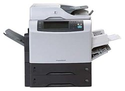
HP LaserJet M4345x
Рейтинг


 Снят с производства
Тип устройства
МФУ
Технология печати
лазерная
Макс. формат
A4
Число страниц в месяц
200000
Скорость печати
A4
43
Цветность печати
черно-белая
Общие характеристики |
|
|---|---|
Размещение |
настольный |
Тип устройства |
МФУ |
Факс |
|
Сканер |
|
Копир |
|
Печать фотографий |
|
Телефон |
|
Цветность печати |
|
Тип |
лазерный/светодиодный |
Технология печати |
лазерная |
Область применения |
большой офис |
Макс. формат |
A4 |
Число страниц в месяц |
200 000 |
Принтер |
|
Пигментные чернила |
|
Печать без полей |
|
Двусторонняя печать |
|
Прямая печать |
|
Время разогрева |
30 |
Макс, разрешение для ч/б печати |
|
| По X | 1 200 |
| По Y | 1 200 |
Скорость ч/б печати |
|
| A4 | 43 |
Время выхода первого отпечатка |
|
| Ч/б | 10 |
Копир |
|
Макс, количество копий за цикл |
999 |
Время выхода первой копии |
10 |
Шаг масштабирования |
0,01 |
Значение масштаба |
|
| Максимальное | 4 |
| Минимальное | 0,25 |
Макс, разрешение (ч/б) |
|
| По X | 600 |
| По Y | 600 |
Сканер |
|
Устройство автоподачи оригиналов |
одностороннее |
Макс. формат оригинала |
A4 |
Тип датчика сканера |
ПЗС (CCD) |
Глубина цвета |
30 бит |
Емкость устройства автоподачи оригиналов |
50 |
Оттенки серого |
256 |
Тип сканера |
планшетный/протяжный |
Макс, размер сканирования |
|
| По X | 227 |
| По Y | 302 |
Разрешение сканера |
|
| По Х | 600 |
Расходные материалы |
|
Печать на: |
|
| Этикетках |
|
| Карточках |
|
| Пленках |
|
| Глянцевой бумаге |
|
| Конвертах |
|
| Матовой бумаге |
|
| Рулоне |
|
| Фотобумаге |
|
| CD/DVD |
|
Плотность бумаги |
|
| Максимальная | 200 |
| Минимальная | 60 |
Факс |
|
Цветной |
|
PC Fax |
|
Телефон |
|
Спикерфон |
|
АОН |
|
Проводная трубка |
|
Caller ID |
|
Автоответчик |
|
Стандарт DECT |
|
Беспроводная трубка |
|
Языки управления |
|
| PostScript |
|
| PostScript 3 |
|
| PCL 5e |
|
| PCL 6 |
|
|
|
|
| PostScript 2 |
|
| PPDS |
|
| PCL 5c |
|
Лотки |
|
Подача бумаги |
|
| Максимальная | 2 100 |
| Стандартная | 1 100 |
Вывод бумаги |
|
| Максимальный | 700 |
| Стандартный | 500 |
Финишер |
|
Брошюровщик |
|
Сортировка со сдвигом |
|
Сортер |
|
Степлер |
|
Интерфейсы |
|
FireWire (IEEE 1394) |
|
LPT |
|
Устройство для чтения карт памяти |
|
RS-232 |
|
Инфракрасный порт |
|
Bluetooth |
|
Wi-Fi |
|
Версия USB |
2,0 |
USB |
|
Ethernet (RJ-45) |
|
Веб-интерфейс |
|
Количество свободных слотов расширения |
2 |
Память/Процессор |
|
Процессор |
MIPS |
Емкость жесткого диска |
40 |
Частота процессора |
480 |
Объем памяти |
256 |
Макс, объем памяти |
512 |
Дополнительная информация |
|
Экран |
|
Мин. системные требования |
|
Поддержка ОС |
|
| Linux |
|
| Windows |
|
| Mac OS |
|
| DOS |
|
Потребляемая мощность |
|
| В режиме ожидания | 280 |
| При работе | 1 265 |
Габариты |
|
Ширина |
762 |
Вес |
63,9 |
Высота |
668 |
Глубина |
566 |
Модули
Paper-feed roller assembly
REGISTRATION ASSEMBLY
Internal components (4 of 5)
Scanner flatbed-unit assembly
Multipurpose assembly
Lifter-drive assembly
ADF ASSEMBLY
ADF pickup-roller assembly
ADF mylar replacement kit
ADF separation pad
ADF pickup-roller cover
Delivery assembly
External panels and covers
3-bin mailbox accessory
Internal components (2 of 5)
ADF mylar-holder assembly
ADF internal components (2 of 3)
ADF internal components (1 of 3)
Internal components (3 of 5)
MAIN DRIVE ASSEMBLY
CASSETTE
Internal components (1 of 5)
Duplex-printing assembly
Upper-plate assembly
Internal components (5 of 5)
REVERSE ASSEMBLY
ADF input tray
Reverse-separation-guide assembly
ADF internal components (3 of 3)
Scanner-base components
Scanner covers
Stapler stacker
Paper-pickup-drive assembly
ADF separation-pad case
Fuser
Electrical, forward assembly
Детали ADF internal components (2 of 3)

| Деталь: | Paper-feed roller assembly |
| Парткод: | RM1-0012-020CN |
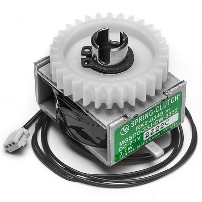
| Деталь: | Clutch, paper feed, electromagnetic (CL101) |
| Парткод: | RK2-0349-000CN |
| Цена: | 1 200 ₽ |

| Деталь: | Gear, 30T (paper-feed roller assembly) |
| Парткод: | RU5-0050-000CN |

| Деталь: | E-ring (paper-feed roller assembly) |
| Парткод: | XD9-0132-020CN |

| Деталь: | REGISTRATION ASSEMBLY |
| Парткод: | RM1-0011-060CN |

| Деталь: | Cross-member, support |
| Парткод: | RC1-2911-000CN |

| Деталь: | Upper plate assembly |
| Парткод: | For reference only |

| Деталь: | CABLE, REVERSE UNIT |
| Парткод: | RM1-1380-000CN |

| Деталь: | Reverse-separation guide assembly |
| Парткод: | RM1-1019-000CN |

| Деталь: | Bolt, hex-head |
| Парткод: | WS9-0255-000CN |

| Деталь: | Cable, output device connection |
| Парткод: | RM1-1371-000CN |

| Деталь: | Cable, output-bin full sensor |
| Парткод: | RM1-1368-000CN |

| Деталь: | Cover, front stopper |
| Парткод: | RC1-2823-000CN |

| Деталь: | Stopper, front lock |
| Парткод: | RL1-0434-000CN |

| Деталь: | Support, gas damper |
| Парткод: | RL1-0436-000CN |

| Деталь: | STOPPER, BUSHING ARM |
| Парткод: | RC1-3090-000CN |

| Деталь: | Arm, door, 1 (top cover) |
| Парткод: | RC1-2827-000CN |

| Деталь: | Cover, door arm (top cover) |
| Парткод: | RC1-2833-000CN |

| Деталь: | Arm, door, 2 (top cover) |
| Парткод: | RC1-2828-000CN |

| Деталь: | Flag, full-detect (output bin) |
| Парткод: | RC1-2863-000CN |

| Деталь: | CABLE, CONTROL PANEL |
| Парткод: | RM1-1381-000CN |

| Деталь: | Holder, output-device-full sensor flag |
| Парткод: | RC1-2864-000CN |

| Деталь: | Cover, Inner Front |
| Парткод: | RC1-3041-000CN |

| Деталь: | Scanner flatbed-unit assembly |
| Парткод: | IR4041K081NI |

| Деталь: | Screw, scanner flatbed |
| Парткод: | 040100FNBBNI |

| Деталь: | Scanner rear cover |
| Парткод: | IR4041P216NI |

| Деталь: | Multipurpose assembly |
| Парткод: | RM1-1572-000CN |
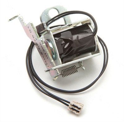
| Деталь: | Solenoid, multipurpose assembly (SL102) |
| Парткод: | RK2-0276-000CN |
| Цена: | 1 200 ₽ |
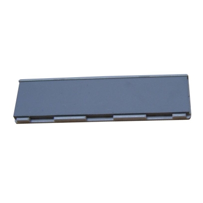
| Деталь: | Plate, main pad support (multipurpose assembly) |
| Парткод: | RL1-0007-000CN |
| Цена: | 460 ₽ |
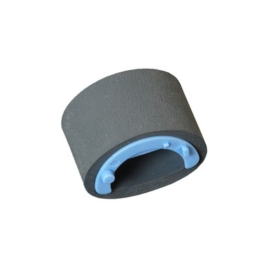
| Деталь: | Roller, pickup, multipurpose assembly |
| Парткод: | RL1-0019-000CN |
| Цена: | 60 ₽ |
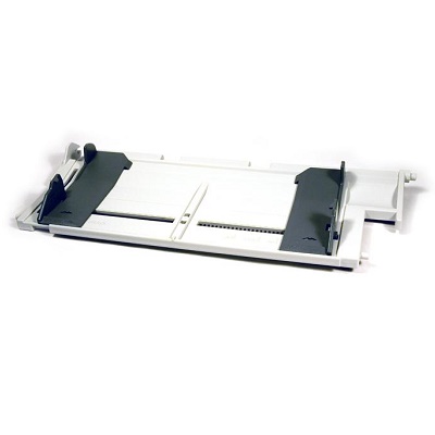
| Деталь: | Multipurpose tray assembly |
| Парткод: | RM1-0005-020CN |
| Цена: | 2 700 ₽ |

| Деталь: | Screw, tapping, truss-head, M3 x 8 |
| Парткод: | XB4-7300-809CN |

| Деталь: | Lifter-drive assembly |
| Парткод: | RM1-1029-000CN |

| Деталь: | ADF ASSEMBLY |
| Парткод: | PF2282K006NI |

| Деталь: | ADF REAR COVER |
| Парткод: | PF2282P044NI |

| Деталь: | ADF cable |
| Парткод: | PF2282K165NI |

| Деталь: | Screw, ADF |
| Парткод: | 030080FWWSNI |
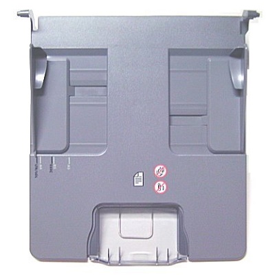
| Деталь: | ADF input tray |
| Парткод: | PF2282K042NI |

| Деталь: | ADF FRONT COVER |
| Парткод: | PF2282P059NI |

| Деталь: | ADF mylar replacement kit |
| Парткод: | Q649667901 |

| Деталь: | ADF white scan background |
| Парткод: | PF2282P339NI |

| Деталь: | ADF mylar holder assembly |
| Парткод: | PF2282K043NI |

| Деталь: | ADF white mylar backing |
| Парткод: | PF2282P025NI |

| Деталь: | ADF, springs for white mylar backing |
| Парткод: | PF2282P343NI |

| Деталь: | ADF left cover |
| Парткод: | PF2282P058NI |

| Деталь: | ADF, springs for left cover |
| Парткод: | PF2282P352NI |

| Деталь: | Screw, ADF, wave 4 x 10 |
| Парткод: | PF2245P369NI |

| Деталь: | ADF jam-access cover |
| Парткод: | PF2282P041NI |

| Деталь: | ADF hinge flaps (ESD) |
| Парткод: | PF2282K166NI |
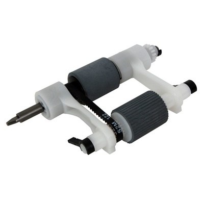
| Деталь: | ADF pickup-roller assembly |
| Парткод: | PF2282K039NI |

| Деталь: | ADF mylar replacement kit |
| Парткод: | Q649667901 |
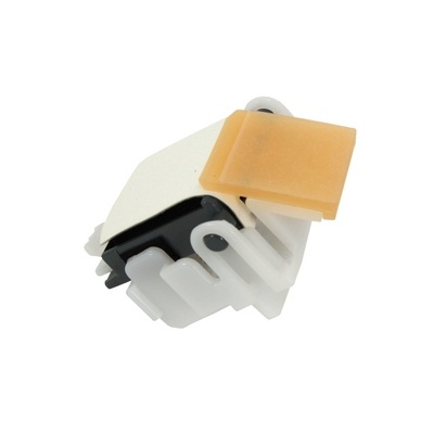
| Деталь: | ADF separation-pad assembly |
| Парткод: | PF2282K035NI |
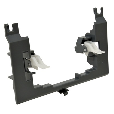
| Деталь: | ADF pickup-roller cover |
| Парткод: | PF2282K040NI |

| Деталь: | DELIVERY ASSEMBLY |
| Парткод: | RM1-1047-000CN |

| Деталь: | Cover, duplexing-unit assembly |
| Парткод: | RM1-1018-000CN |

| Деталь: | Output-bin assembly |
| Парткод: | RM1-0940-000CN |

| Деталь: | DELIVERY ASSEMBLY |
| Парткод: | RM1-1047-000CN |

| Деталь: | Cover, formatter |
| Парткод: | RC1-3035-000CN |

| Деталь: | COVER, REAR |
| Парткод: | RM1-1017-000CN |

| Деталь: | Cover, front corner |
| Парткод: | RL1-0457-000CN |

| Деталь: | Cover, right assembly |
| Парткод: | RM1-1016-000CN |

| Деталь: | Cover, right lower assembly |
| Парткод: | RM1-1033-000CN |

| Деталь: | Control-panel assembly |
| Парткод: | CB425-60127 |

| Деталь: | Cover, front assembly |
| Парткод: | RM1-1100-000CN |

| Деталь: | Screw, tapping, pan-head, M4 x 10 |
| Парткод: | XB4-7401-0007CN |

| Деталь: | Switch, power |
| Парткод: | RC1-3044-000CN |

| Деталь: | Cover, cassette, left side |
| Парткод: | RC1-3043-000CN |

| Деталь: | 3-bin mailbox replacement unit |
| Парткод: | Q5692-67901 |

| Деталь: | Jam-access door, 3-bin mailbox |
| Парткод: | RM1-0981-000CN |

| Деталь: | FRONT COVER |
| Парткод: | RM1-0985-000CN |

| Деталь: | REAR COVER |
| Парткод: | RC1-2691-000CN |

| Деталь: | Paper delivery tray assembly |
| Парткод: | RM1-0940-000CN |

| Деталь: | MBM driver board |
| Парткод: | RM1-1124-000CN |

| Деталь: | Fuser (100127 volt) |
| Парткод: | RM1-1043-000CN |

| Деталь: | Fuser (220240 volt) |
| Парткод: | RM1-1044-000CN |

| Деталь: | REVERSE ASSEMBLY |
| Парткод: | RM1-1022-000CN |

| Деталь: | Holder, door switch |
| Парткод: | RC1-3063-000CN |

| Деталь: | Microswitch (SW101) |
| Парткод: | WC4-5139-000CN |

| Деталь: | Stopper, hinge shaft |
| Парткод: | RC1-3124-000CN |

| Деталь: | CABLE, DOOR SWITCH |
| Парткод: | RM1-1397-000CN |

| Деталь: | Case, envelope-feeder connector |
| Парткод: | RC1-0245-000CN |

| Деталь: | Cable, envelope-feeder connector |
| Парткод: | RM1-1193-000CN |

| Деталь: | Hinge, door, right-side |
| Парткод: | RC1-2901-000CN |

| Деталь: | Screw, with washer, M3 x 6 |
| Парткод: | XB2-7300-607CN |
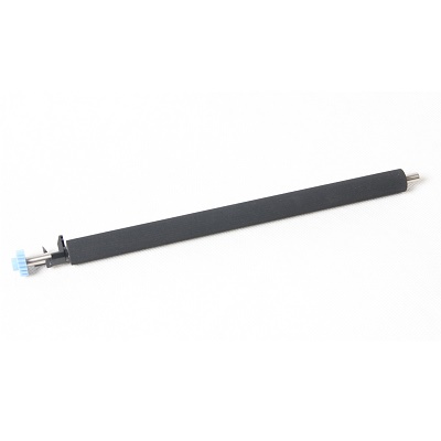
| Деталь: | Roller assembly, transfer |
| Парткод: | RM1-1110-000CN |
| Цена: | 2 800 ₽ |

| Деталь: | Sensor assembly, right door |
| Парткод: | RM1-1045-000CN |

| Деталь: | Cover, handle, lower right |
| Парткод: | RC1-2881-000CN |

| Деталь: | SPACER, SCREW |
| Парткод: | RC1-0392-000CN |

| Деталь: | Electrical/forward assembly |
| Парткод: | For reference only |

| Деталь: | Fuser entrance guide |
| Парткод: | RM1-1046-000CN |

| Деталь: | ADF mylar-holder assembly |
| Парткод: | PF2282K043NI |

| Деталь: | ADF hinge, left |
| Парткод: | PF2282K041NI |

| Деталь: | ADF hinge, right |
| Парткод: | PF2282K008NI |

| Деталь: | ADF output-bin paper stop |
| Парткод: | PF2282P061NI |

| Деталь: | Screw, ADF |
| Парткод: | NS-SCR00029NI |

| Деталь: | ADF output-bin-base cover |
| Парткод: | PF2282P060NI |

| Деталь: | Motor, DC 24-volt, (M101) |
| Парткод: | RK2-0272-000CN |

| Деталь: | Motor, DC 24-volt, (M102) |
| Парткод: | RK2-0274-000CN |

| Деталь: | Screw, tapping, M3 x 6 |
| Парткод: | XA9-1503-000CN |

| Деталь: | MAIN DRIVE ASSEMBLY |
| Парткод: | RM1-1049-000CN |

| Деталь: | LIFTER DRIVE ASSEMBLY |
| Парткод: | RM1-1029-000CN |

| Деталь: | Rod, link |
| Парткод: | RC1-2902-000CN |

| Деталь: | Multipurpose tray assembly |
| Парткод: | RM1-1572-000CN |

| Деталь: | Cover, envelope-feeder slot |
| Парткод: | RL1-0455-000CN |

| Деталь: | CASSETTE RAIL ASSEMBLY, RIGHT |
| Парткод: | RM1-1012-000CN |

| Деталь: | CASSETTE RAIL ASSEMBLY, LEFT |
| Парткод: | RM1-1011-000CN |

| Деталь: | SPRING, GROUNDING |
| Парткод: | RU5-2251-000CN |

| Деталь: | GUIDE, REAR |
| Парткод: | RC1-2884-000CN |

| Деталь: | Cover, side, rear |
| Парткод: | RC1-3042-000CN |

| Деталь: | Rod, switch, front |
| Парткод: | RC1-2980-000CN |

| Деталь: | LINK, SWITCH |
| Парткод: | RC1-3003-000CN |

| Деталь: | HOLDER, LINK |
| Парткод: | RC1-3002-000CN |

| Деталь: | Screw, tapping, truss-head, M4 x 16 |
| Парткод: | XB4-7401-605CN |

| Деталь: | MAIN DRIVE ASSEMBLY |
| Парткод: | RM1-1049-000CN |

| Деталь: | Cassette (tray 2, 3, 4 or 5) |
| Парткод: | RM1-1001000CN |

| Деталь: | Gear, 20T (cassette) |
| Парткод: | RC1-0331-000CN |
| Цена: | 320 ₽ |

| Деталь: | Lever, paper-size-sensing (cassette) |
| Парткод: | RC1-2782-000CN |

| Деталь: | Gear, 14T (cassette) |
| Парткод: | RU5-0254-000CN |

| Деталь: | Gear, 80T (cassette) |
| Парткод: | RU5-0253-000CN |

| Деталь: | Guide, cassette, front |
| Парткод: | RC1-3020-000CN |

| Деталь: | CASSETTE |
| Парткод: | RM11001000CN |

| Деталь: | Laser/Scanner assembly |
| Парткод: | RM1-1573-000CN |

| Деталь: | Screw, RS, M3 x 12 |
| Парткод: | XA9-1447-000CN |

| Деталь: | Cable, image scanner (print engine) |
| Парткод: | RM1-1398-000CN |

| Деталь: | REGISTRATION ASSEMBLY |
| Парткод: | RM1-0011-060CN |

| Деталь: | Cable, laser (print engine) |
| Парткод: | RM1-1367-000CN |

| Деталь: | Cable, beam-detect to scanner (print engine) |
| Парткод: | RM1-1372-000CN |

| Деталь: | LEVER, SHUTTER |
| Парткод: | RC1-3106-000CN |

| Деталь: | Flag, shutter |
| Парткод: | RC1-0378-000CN |

| Деталь: | SPRING, TORSION |
| Парткод: | RC1-0379-000CN |
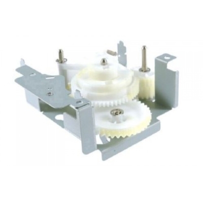
| Деталь: | Paper-pickup-drive assembly |
| Парткод: | RM1-0034-070CN |
| Цена: | 5 700 ₽ |

| Деталь: | Solenoid (SL101) |
| Парткод: | RK2-0269-000CN |

| Деталь: | GEAR, 18T |
| Парткод: | RU5-0045-020CN |

| Деталь: | GEAR, 23T |
| Парткод: | RU5-0256-000CN |

| Деталь: | Guide, paper sensing (PS101) |
| Парткод: | RM1-1010-000CN |

| Деталь: | SPRING, TENSION |
| Парткод: | RC1-0167-000CN |

| Деталь: | Photointerrupter (PS107) |
| Парткод: | WG8-5624-000CN |
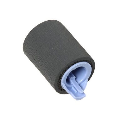
| Деталь: | Roller, paper-feed (cassette) |
| Парткод: | RM1-0037-020CN |
| Цена: | 370 ₽ |

| Деталь: | LIMITER, TORQUE |
| Парткод: | RC1-2758-000CN |

| Деталь: | Roller, paper-pickup (cassette) |
| Парткод: | RM1-0036-000CN |

| Деталь: | SPRING, TORSION |
| Парткод: | RC1-0061-000CN |

| Деталь: | Roller, paper-feed assembly |
| Парткод: | RM1-0012-020CN |

| Деталь: | Flag, paper-feed sensor |
| Парткод: | RC1-0060-000CN |

| Деталь: | Thermistor (TH3) |
| Парткод: | RK2-0359-000CN |

| Деталь: | Screw, S, M3 x 8 |
| Парткод: | XA9-1500-000CN |

| Деталь: | Fan, main cooling (FN101) |
| Парткод: | RK2-0278-000CN |

| Деталь: | Fan, reversing unit (FN103) |
| Парткод: | RK2-0280-000CN |

| Деталь: | Cover, left-side, front |
| Парткод: | RC1-3052-000CN |

| Деталь: | Complete print engine (110 volt) |
| Парткод: | CB425-69001 |

| Деталь: | Complete print engine (220 volt) |
| Парткод: | CB425-69002 |

| Деталь: | Duplex-printing assembly |
| Парткод: | Q5969-67901 |

| Деталь: | Rod, link (upper plate) |
| Парткод: | RC1-2830-000CN |

| Деталь: | Cover, rear lock (upper plate) |
| Парткод: | RC1-2821-000CN |

| Деталь: | Holder, right shutter (upper plate) |
| Парткод: | RC1-2855-000CN |

| Деталь: | Guide, legal-size (upper plate) |
| Парткод: | RC1-2854-000CN |

| Деталь: | Guide, cartridge (upper plate) |
| Парткод: | RC1-2853-000CN |

| Деталь: | Support, cartridge (upper plate) |
| Парткод: | RC1-2856-000CN |

| Деталь: | Link, handle (upper plate) |
| Парткод: | RC1-2822-000CN |

| Деталь: | Handle, lock (upper plate) |
| Парткод: | RC1-2818-000CN |

| Деталь: | Cover, lock, front (upper plate) |
| Парткод: | RC1-2820-000CN |

| Деталь: | Block, guide support (upper plate) |
| Парткод: | RC1-3102-000CN |

| Деталь: | Screw, RS, M3 x 6 |
| Парткод: | XA9-1495-000CN |

| Деталь: | Fan, DC controller (FN104) |
| Парткод: | RK2-0472-000CN |

| Деталь: | Fan, print cartridge (FN102) |
| Парткод: | RK2-0280-000CN |

| Деталь: | Power supply, PFC (100127 volt) |
| Парткод: | RM1-1013-000CN |

| Деталь: | Power supply, PFC (220240 volt) |
| Парткод: | RM1-1014-000CN |

| Деталь: | DC controller PCA |
| Парткод: | RM1-1354-000CN |

| Деталь: | SPRING, COMPRESSION |
| Парткод: | RU5-2265-000CN |

| Деталь: | Cable, optional 500-sheet feeder connection |
| Парткод: | RM1-1370-000CN |
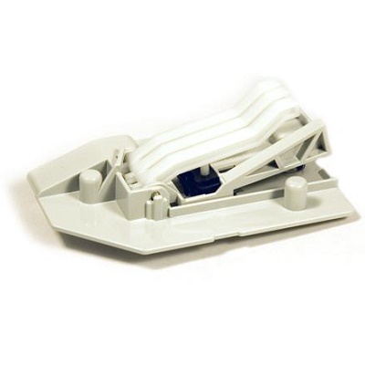
| Деталь: | Sensor assembly, paper size (SW102) |
| Парткод: | RM1-0041-020CN |
| Цена: | 1 400 ₽ |

| Деталь: | Swing-plate assembly |
| Парткод: | RM1-0043-020CN |

| Деталь: | CABLE, POWER |
| Парткод: | RM1-1375-000CN |

| Деталь: | Cable, fan docking (for DC-controller fan) |
| Парткод: | RM1-1376-000CN |

| Деталь: | Guide assembly, flat-flexible cable |
| Парткод: | RM1-1027-000CN |

| Деталь: | Formatter assembly |
| Парткод: | CB425-67901 |

| Деталь: | SCREW, STEPPED, M3 |
| Парткод: | RC1-0266-020CN |

| Деталь: | REVERSE ASSEMBLY |
| Парткод: | RM1-1022-000CN |

| Деталь: | Sensor, reverse-unit (PS109) |
| Парткод: | RM1-1570-000CN |

| Деталь: | Sensor, reverse-unit jam (PS111) |
| Парткод: | RM1-1571-000CN |

| Деталь: | Motor, crossing, (stepping) (M104) |
| Парткод: | RK2-0473-000CN |

| Деталь: | Solenoid, reverse-unit (SL105) |
| Парткод: | RK2-0485-000CN |

| Деталь: | Motor, delivery (stepping) (M106) |
| Парткод: | RK2-0475-000CN |

| Деталь: | Motor, reverse-unit (stepping) (M105) |
| Парткод: | RK2-0474-000CN |

| Деталь: | Reverse-unit PCA |
| Парткод: | RM1-1379-000CN |

| Деталь: | Solenoid, reversing-roller separation (SL106) |
| Парткод: | RK2-0486-000CN |

| Деталь: | Screw, TP, M3 x 4 |
| Парткод: | XB6-7300-406CN |

| Деталь: | ADF input tray |
| Парткод: | PF2282K042NI |

| Деталь: | Screw, ADF, button, M3 x 8 |
| Парткод: | IR4041P021NI |

| Деталь: | Reverse-separation-guide assembly |
| Парткод: | RM1-1019-000CN |

| Деталь: | ADF jam-access latch |
| Парткод: | PF2282K164NI |

| Деталь: | ADF clear plastic paper guide |
| Парткод: | PF2282P353NI |

| Деталь: | ADF pickup-roller assembly |
| Парткод: | PF2282K039NI |

| Деталь: | ADF pickup-roller cover |
| Парткод: | PF2282K040NI |

| Деталь: | Scanner controller PCA |
| Парткод: | IR4041K512NI |

| Деталь: | Scanner fan-filter cover |
| Парткод: | IR4041P217NI |

| Деталь: | Scanner-fan filter |
| Парткод: | IR4041P007NI |

| Деталь: | Scanner left cover |
| Парткод: | IR4041K114NI |

| Деталь: | Scanner, spring for left cover |
| Парткод: | IR4041P041NI |

| Деталь: | Scanner-carriage-lock cover |
| Парткод: | IR4041P214NI |

| Деталь: | Scanner top-cover flatbed flange |
| Парткод: | IR4041P125NI |

| Деталь: | Scanner right cover |
| Парткод: | IR4041P213NI |

| Деталь: | 500 sheet stapler/stacker replacement unit |
| Парткод: | Q5691-60501 |

| Деталь: | Door, jam access |
| Парткод: | RC1-2597-000CN |

| Деталь: | FRONT COVER |
| Парткод: | RM1-0942-000 |

| Деталь: | REAR COVER |
| Парткод: | RC1-2598-000CN |

| Деталь: | Jog guide assembly |
| Парткод: | RM1-0947-000CN |

| Деталь: | Stapler unit |
| Парткод: | RK2-0507-000CN |

| Деталь: | Staple cartridge |
| Парткод: | C8085-60541 |

| Деталь: | Stapler/stacker driver board |
| Парткод: | RM1-1123-000CN |

| Деталь: | Paper delivery tray assembly |
| Парткод: | RM1-0940-000CN |

| Деталь: | Paper-pickup-drive assembly |
| Парткод: | RM1-0034-070CN |
| Цена: | 5 700 ₽ |

| Деталь: | ADF separation-pad case |
| Парткод: | PF2282K034NI |

| Деталь: | ADF SEPARATION PAD |
| Парткод: | PF2282K035NI |

| Деталь: | Fuser (100127 volt) |
| Парткод: | RM1-1043-000CN |

| Деталь: | Fuser (220240 volt) |
| Парткод: | RM1-1044-000CN |

| Деталь: | SCREW, STEPPED |
| Парткод: | RS1-9004-020CN |

| Деталь: | Screw, M3 x 8 |
| Парткод: | XA9-0650-000CN |

| Деталь: | Screw, RS, M3 x 8 |
| Парткод: | XA9-1449-000CN |
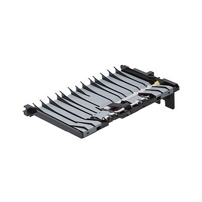
| Деталь: | Paper-feed assembly |
| Парткод: | RM1-0025-040CN |
| Цена: | 2 600 ₽ |

| Деталь: | Cable, flat-flexible (engine power supply) |
| Парткод: | RK2-0470-000CN |

| Деталь: | Cable, flat-flexible (engine power supply) |
| Парткод: | RK2-0469-000CN |

| Деталь: | Engine power supply assembly (100127 volt) |
| Парткод: | RM1-1041-000CN |

| Деталь: | Engine power supply assembly (220240 volt) |
| Парткод: | RM1-1042-000CN |

| Деталь: | Cable, duplexing-unit grounding |
| Парткод: | RM1-1400-000CN |

| Деталь: | Screw, with washer, M3 x 6 |
| Парткод: | XA9-1420-000CN |

| Деталь: | Screw, flathead, RS, M3 x 6 |
| Парткод: | XA9-1464-000CN |
Коды ошибок
10.00.YY
10.10.YY
10.32.00
11.XX
13.01.00
13.02.00
13.05.00
13.09.00
13.12.07
13.12.08
13.12.09
13.12.10
13.12.11
13.13.00
13.20.00
13.21.00
13.31.00
13.33.00
13.JJ.NT
20
21
22
30.1.1
30.1.10
30.1.15
30.1.18
30.1.19
30.1.2
30.1.22
30.1.23
30.1.24
30.1.25
30.1.29
30.1.3
30.1.36
30.1.6
30.1.7
30.1.8
40
41.2
41.3
49.XXXXX
50.1
50.2
50.3
50.4
50.5
51.10
51.20
52.0
52.1
52.2
53.10.01
54.01
54.XX
55.01.YY
55.02.YY
55.04.YY
55.05
56.1
56.2
57.01
57.03
57.04
57.05
57.07
58.2
58.3
58.4
59.0
59.1
59.2
59.4
59.A
60.XX
62
64
65.12.99
66.00.15
66.12.01
66.12.02
66.12.03
68.0
68.1
68.X
69.X
79.XXXX
8X.YYYY
Описание
| Error code: | 10.00.YY |
| Display: | 10.XX.YY SUPPLY MEMORY ERROR |
| Description: | The MFP cannot read or write to at least one print cartridge e-label or an e-label is missing from a print cartridge. E-label is damaged. |
| Remedy: | 1. Reinstall the print cartridge, or install a new HP print cartridge. 2. Verify that connector J97 on the DC controller PCA is firmly seated. |
| Error code: | 10.10.YY |
| Display: | 10.XX.YY SUPPLY MEMORY ERROR |
| Description: | The MFP cannot read or write to at least one print cartridge e-label or an e-label is missing from a print cartridge. MFP cannot communicate with the e-label. |
| Remedy: | 1. Reinstall the print cartridge, or install a new HP print cartridge. 2. Verify that connector J97 on the DC controller PCA is firmly seated. |
| Error code: | 10.32.00 |
| Display: | 10.32.00 - Unauthorized Supply |
| Description: | A supply has been installed that does not pass the authentication test for genuine HP supplies. |
| Remedy: | If you believe you purchased a genuine HP supply, visit us at www.hp.com/go/ anticounterfeit. Any repair required as a result of using non-HP supplies or unauthorized supplies are not covered under warranty. HP cannot ensure the accuracy or the availability of certain features. To continue printing, touch OK. |
| Error code: | 11.XX |
| Display: | 11.XX INTERNAL CLOCK ERROR |
| Description: | The real time clock has experienced an error. |
| Remedy: | 1. Power cycle the product to see if the message clears. 2. If possible, print a configuration page to record product information, and then perform an NVRAM initialization routine. If the initialization routine is successful, you will need to re-enter several configuration parameters (such as the page count and the serial number). 3. If the error persists, replace the formatter PCA. |
| Error code: | 13.01.00 |
| Display: | 13.01.00 Jam in Tray 1 |
| Description: | The Tray 1 pickup roller or solenoid might not be working correctly. |
| Remedy: | 1. Load paper in Tray 1, and then use the paper path test to pull paper. Verify that the roller rotates. 2. If someone has performed maintenance on the product recently, verify that the Tray 1 pickup roller, feed roller, and separation roller have been installed correctly. 3. From the DIAGNOSTICS menu, run the multipurpose tray (Tray 1) solenoid component test to verify that the solenoid moves when energized. Listen for an audible “click” when the test is initiated. If the solenoid is not being energized, verify that the solenoid connector is attached to connector J71 on the DC controller PCA. 4. If the error persists, replace the Tray 1 solenoid (SL102). |
| Error code: | 13.02.00 |
| Display: | 13.02.00 Jam inside upper right door |
| Description: | Stay jam at SR5 (top/registration sensor). SR5 continues to detect media, after the media is originally detected, longer than specified. |
| Remedy: | Clear the jam. 1. Check for paper or other obstructions to the paper path in Tray 2 and before the registration area. 2. Check SR5 (top/registration sensor) and flag for correct mechanical functionality. Repair or replace if necessary. 3. Check connector J319 on the dc controller. 4. Replace the HVPS. 5. Replace the dc controller. |
| Error code: | 13.05.00 |
| Display: | 13.05.00 JAM INSIDE TOP COVER |
| Description: | Paper failed to reach the delivery sensor within a specified period of time when a print job was initiated. When troubleshooting paper jams, always observe where the leading edge of the paper stops in the jam. |
| Remedy: | 1. Verify that nothing is obstructing paper movement within the paper path. 2. Verify that the fuser motor (M2) connector is firmly seated. The fuser motor wiring is hard-wired to the back of the ECU at connector J501. The motor connector is free-standing behind the ECU. To see if the fuser motor is functional, observe the output stacker rollers while turning on the device. If the rollers rotate, the motor is functional. If they do not rotate, verify the connection. |
| Error code: | 13.09.00 |
| Display: | 13.09.00 Jam inside left door |
| Description: | A jam is in the face-down bin. The leading edge of the media failed to reach the face-down bin delivery sensor (PS1451) within the specified time. |
| Remedy: | - Clear the jam in the area indicated. - Close the door to allow the product to attempt to clear the jam. - Reseat the connections to the DC controller. - Make sure that the delivery flags move smoothly. - Run a service test. - Replace the delivery unit. - Replace the DC controller. |
| Error code: | 13.12.07 |
| Display: | 13.12.07 Stapler jam inside front stapler door |
| Description: | Stapler jam. The stapler could not complete its cycle but was able to return to the home position. |
| Remedy: | 1. Open the front door, remove the staple cartridge, and perform the following tasks: - Lift the small tab at the green dot to release the staples. - Remove any damaged staples. - Lock the staple cartridge by pressing the small tab until it clicks into place. - Reinstall the staple cartridge. 2. If the problem persists, install a new staple cartridge. 3. If, after installing a new staple cartridge, the problem perisists, remove the staple cartridge and perform the following tasks: - Remove the front cover. - Remove the stapler. - Clear any loose or jammed staples from the stapler. - Reinstall the stapler. 4. If the problem persists, replace the stapler. |
| Error code: | 13.12.08 |
| Display: | 13.12.08 Jam in stacker bin area |
| Description: | Stapler jam. Stay jam in accumulator. SR2103 (delivery sensor) stayed activated too long. SR2103 is located in the paper path of the stapler/stacker at the exit rollers to the stacker-output bin. SR2103 is the exit sensor for the stapler/ stacker and senses media-presence as media exits the stapler/stacker into the stacker-output bin. |
| Remedy: | 1. Remove any media at the exit rollers of the stapler/stacker. 2. Open the upper left door and perform the following tasks: ?? Remove any media from the paper path. - Press down on the upper portion of the green guide and remove any media from between the green guide and the stapler/stacker exit rollers. - Check the operation of SR2103 (delivery sensor) and the sensor flag. If the sensor or the sensor flag is not working, replace the stapler/ stacker alignment assembly. 3. If, after performing the previous steps, the problem persists, replace the stapler/stacker control board. |
| Error code: | 13.12.09 |
| Display: | 13.12.09 Jam inside upper left door |
| Description: | Stapler jam. Stay jam in entry. SR2100 (inlet media sensor) stayed activated too long. SR2100 is located in the stapler/stacker feed assembly, sensing media entering the stapler/stacker. |
| Remedy: | 1. Open the lower left door and remove any paper or obstructions in the paper path. 2. Remove the stapler/stacker feed assembly and perform the following tasks. - Remove any media from SR2100. - Check the operation of the sensor flag and sensor-flag spring and make sure that the flag does not block the sensor. If the flag or the spring is damaged, replace the stapler/stacker feed assembly. - Clean SR2100 by blowing air gently into the sensing area. Check the sensor for correct mounting, cable connection, and alignment with the sensor flag. If the sensor is damaged or nor working, replace the sensor. - Check operation of the drive gears and belts at the rear of the stapler/ stacker feed assembly. Turning any of the gears should turn all of the rollers in the assembly. If the gears or belts are not working, replace the stapler/stacker feed assembly. |
| Error code: | 13.12.10 |
| Display: | 13.12.10 Jam inside upper left door |
| Description: | Stapler jam. Delay jam in entry. The page did not arrive at SR2100 (inlet media sensor) within the expected time. SR2100 is located in the stapler/stacker feed assembly, sensing media entering the stapler/stacker. |
| Remedy: | 1. Open the lower left door and remove any paper or obstructions in the paper path. 2. Turn off the device, disconnect the sensor connection at J2104 on the stapler/stacker control board, and then turn the device back on. If 13.12.11 does not appear on the control-panel display after the device warms up, replace SR2100. 3. Open the upper left door. If media is jammed in this area, replace the stapler/ stacker feed assembly. 4. Check the standard (lower) output bin to see whether media exited the device to the bin. Media exiting the device to the malfunction. - If SL2100 (flapper solenoid) is not working, replace the stapler/ stacker feed assembly. - If the flapper is broken, replace the delivery assembly. - If the SL2100 and the flapper are both working correctly, then the problem is in the stapler/stacker control board. Replace the board. 5. Open the lower left door. If media is jammed in this area, remove the stapler/ stacker feed assembly without clearing the jam. After removing the assembly, observe the location of the leading edge of the media and then perform the following tasks: - If the leading edge reached the entrance rollers of the feed assembly but stopped and jammed there, check operation of the drive gears and belts at the rear of the stapler/stacker feed assembly. Turning any of the gears should turn all of the rollers in the assembly. - If the gears or belts are not working, replace the stapler/ stacker feed assembly. - If all rollers turn correctly, replace the alignment assembly. - If the leading edge stopped at or stopped just past SR2100 (inlet media sensor), replace the stapler/ stacker feed assembly. 6. If, after performing the previous steps, the problem persists, replace the stapler/stacker control board. |
| Error code: | 13.12.11 |
| Display: | 13.12.11 Jam inside upper left door |
| Description: | Stapler jam. Initial jam at entry. At power-on, media was detected at SR2100 (inlet media sensor). SR2100 is located in the stapler/stacker feed assembly. SR2100 senses media entering the stapler/stacker. |
| Remedy: | 1. Open the upper left door and remove any media. 2. Open the lower left door and remove any media. 3. Check connection J2104 on the stapler/ stacker control board. 4. Remove the stapler/stacker feed assembly and perform the following tasks. - Remove any media from SR2100. - Check the operation of the sensor flag and sensor-flag spring and make sure that the flag does not block the sensor. If the flag or the spring is damaged, replace the stapler/stacker feed assembly. - Clean SR2100 by blowing air gently into the sensing area. Check the sensor for correct mounting, cable connection, and alignment with the sensor flag. If the sensor is damaged or nor working, replace the sensor. - Check operation of the drive gears and belts at the rear of the stapler/ stacker feed assembly. Turning any of the gears should turn all of the rollers in the assembly. If the gears or belts are not working, replace the stapler/stacker feed assembly. 5. If, after performing the previous steps, the problem persists, replace the stapler/stacker control board. |
| Error code: | 13.13.00 |
| Display: | 13.13.00 Jam inside left door |
| Description: | A jam is in the duplexer area. The trailing edge of the media did not leave the duplexer paper sensor (PS2004) within a specified time. |
| Remedy: | - Clear the jam. - Close the door to allow the product to attempt to clear the jam. - Replace the duplexer. |
| Error code: | 13.20.00 |
| Display: | 13.20.00 JAM INSIDE <LOCATION> |
| Description: | Paper has not moved past a certain paper sensor. <LOCATION> can be one of the following locations. • TRAY 2 • TOP COVER • REAR DOOR • DUPLEXER |
| Remedy: | • TRAY 2 Remove the tray, and then check the paper path for obstructions. Perform a manual sensor test and observe the prefeed sensor (PS102) status (B). Toggle the sensor flag to determine if the status changes. • TOP COVER Remove the print cartridge, and then check the paper path for obstructions. Verify that the top-of-page sensor (PS103) and the media width sensors (PS106 and PS108) are unblocked. Perform a manual sensor test and observe the status of these sensors. Toggle the sensor flags to determine if their status changes. • REAR DOOR Open or remove the rear face-up bin, and then check the paper path on each side of the fusing assembly for obstructions. Remove the fuser, if necessary. Perform a manual sensor test and observe the fuser delivery sensor (PS700) status (C). Toggle the sensor flag to determine if the status changes. • DUPLEXER Remove the duplexer, and then check the paper path for obstructions. If the message persists, replace the duplexer. |
| Error code: | 13.21.00 |
| Display: | 13.21.00 Jam inside left door |
| Description: | A door is open. |
| Remedy: | - Clear the jam. - Close the door to allow the product to attempt to clear the jam. - Run a paper path test. - Run a service test. - Check the function of the interlock switches. - Replace the left door. |
| Error code: | 13.31.00 |
| Display: | 13.31.00 JAM INSIDE FRONT DOOR |
| Description: | A jam has occurred inside the front door. |
| Remedy: | 1. Verify that nothing is obstructing paper movement within the paper path. 2. Verify that the face-up tray sensor (PS1) is functioning properly. 3. Verify that connection J505 is firmly seated on the ECU. 4. Open and close the cartridge door to clear the error message |
| Error code: | 13.33.00 |
| Display: | 13.33.00 |
| Description: | Output jam. Media did not arrive at SR7 (delivery sensor) within the specified time |
| Remedy: | 1. Clear the jam. 2. Check for paper or other obstructions between SR6 (fuser exit sensor) and SR7. 3. Check the fuser and the pressurerelease assembly for correct seating and functionality. 4. Check SR6 and SR7 for correct mechanical functionality. Replace if necessary. 5. Check connector J310 on the dc controller. 6. Replace the dc controller. |
| Error code: | 13.JJ.NT |
| Display: | 13.JJ.NT PAPER JAM OPEN INPUT TRAYS |
| Description: | A jam has occurred in an input tray. |
| Remedy: | 1. Open the top cover. 2. Remove the print cartridge and any paper. 3. Reinstall the print cartridge and close the top cover. 4. Close all trays. |
| Error code: | 20 |
| Description: | Vertical image or label drift |
| Causes: | The printer is using non-continuous labels but is configured in continuous mode. The media sensor is positioned incorrectly. The media sensor is calibrated improperly. The platen roller is dirty. Improper printhead pressure settings (toggles). Improperly loaded ribbon or media. Incompatible media. |
| Remedy: | Configure the printer for non-continuous and run calibration routine, if necessary. Ensure that the media sensor is properly positioned to read a single/consistent interlabel gap. See Calibrate Media and Ribbon Sensor Sensitivity on page 90. Clean the platen roller. See Clean the Printhead and Platen Roller on page 131. Adjust the printhead pressure to ensure proper functionality. Verify that the printer is loaded properly. Ensure that the interlabel gaps or notches are 2 to 4 mm and consistently placed. Media must not exceed minimum specifications for mode of operation. |
| Error code: | 21 |
| Description: | The bar code printed on a label does not scan. |
| Causes: | The bar code is not within specifications because the print is too light or too dark. Not enough blank space around the bar code. |
| Remedy: | Perform the FEED Self Test on page 120. Adjust the darkness or print speed settings as necessary. Leave at least 1/8 in. (3.2 mm) between the bar code and other printed areas on the label and between the bar code and the edge of the label. |
| Error code: | 22 |
| Description: | Loss of printing registration on labels. Excessive vertical drift in top-of-form registration. |
| Causes: | The platen roller is dirty. Media guides are positioned improperly. The media type is set incorrectly. The media is loaded incorrectly. |
| Remedy: | Clean the platen roller according to the instructions in Clean the Printhead and Platen Roller on page 131. Ensure that the media guides are properly positioned. Set the printer for the correct media type (gap/notch, continuous, or mark). See Set Media Type on page 81. Load media correctly. See Load Media on page 58. |
| Error code: | 30.1.1 |
| Display: | 30.1.1 |
| Description: | Flatbed cover open The scanner flatbed cover is open. |
| Remedy: | 1. If the cover is open, close the cover. 2. If the cover is closed, check the cover sensor at the right rear of the scanner for correct mechancical functionality. 3. Check connector 9 on the scanner control board. 4. Replace the lid sensor assembly or replace the scanner. |
| Error code: | 30.1.10 |
| Display: | 30.1.10 Scan failure |
| Description: | The product has experienced an ADF fan error. |
| Remedy: | - Verify that the fan is not functioning while the product is turned on. - Check for loose connections and broken, frayed, or pinched wires. - Reseat the fan connector at scanner control PCA location J109, and connector J156 on the ADF fan. - Replace the ADF fan. - Replace the SCB. |
| Error code: | 30.1.15 |
| Display: | 30.1.15 Scan failure |
| Description: | A condition has prevented the scan engine from initializing. |
| Remedy: | - Verify that all covers are installed correctly and that the ADF and the ADF feeder are closed. - Turn the product off, and then on. - If the error persists, run the sensors diagnostic test to verify that the sensors are functioning correctly. - Check the LED status on the control panel. Follow the troubleshooting instructions if the LEDs are not in the ready state. |
| Error code: | 30.1.18 |
| Display: | 30.1.18 Scan failure |
| Description: | The product has experienced an ASIC error. |
| Remedy: | - Turn the product off, and then disconnect the power cord. - Connect the power cord, and then turn the product on. - Check connections to the SCB. - Check connections to the intermediate PCA, the analog processor PCA, and the CCD driver PCA. - Replace the SCB. - Replace the flatbed optical assembly. |
| Error code: | 30.1.19 |
| Display: | 30.1.19 Scan failure |
| Description: | Lamp error |
| Remedy: | - Turn the product off, and then on. - Check to see that the scanner lamp illuminates while the product is turned on. - Check the connections to the SCB. - Replace the SCB. - Replace the flatbed optical assembly. |
| Error code: | 30.1.2 |
| Display: | 30.1.2 |
| Description: | Jam in document feeder The ADF is jammed. NOTE: Appears as 30.01.02 on the event log. |
| Remedy: | 1. Clear the jam. 2. If the ADF continues to jam, make sure that the document meets media specifications for the ADF. 3. Open the ADF cover and inspect the paper path for damage or obstructions. 4. Check the pickup rollers and separation pad for excessive wear or contamination. Replace if necessary. 5. Check the ADF paper-path sensors for correct operation. 6. Check all connectors on the ADF control board and scanner control board for loose connections. 7. If, after performing all of the previous steps, the ADF continues to jam, replace the ADF. |
| Error code: | 30.1.22 |
| Display: | 30.1.22 Scan failure |
| Description: | CP processing error. |
| Remedy: | - Turn the product off, and then disconnect the power cord. - Connect the power cord, and then turn the product on. |
| Error code: | 30.1.23 |
| Display: | 30.1.23 |
| Description: | Calibration failed A scanner calibration error has occurred. |
| Remedy: | Check the target for correctness and re-run the scanner calibration. |
| Error code: | 30.1.24 |
| Display: | 30.1.24 |
| Description: | Document feeder cover open The ADF jam-access door is open. |
| Remedy: | 1. Clear the jam and close the ADF jamaccess door. 2. Check the ADF cover sensor and the flag for correct mechanical functionality. 3. Check connector J3 on the ADF control board. 4. If the message persists, replace the ADF control board or replace the ADF. |
| Error code: | 30.1.25 |
| Display: | 30.1.25 Scan failure |
| Description: | Copy processor board error. |
| Remedy: | - Turn the product off, and then disconnect the power cord. - Connect the power cord, and then turn the product on. - Check the copy processor LED. - Check connections to the copy processor board. - Check the scan engine cable connection. - Replace the copy processor board. |
| Error code: | 30.1.29 |
| Display: | 30.1.29 ADF output bin full |
| Description: | The ADF output bin is full. |
| Remedy: | - Empty the ADF output bin. - Check the connection to the ADF output bin full sensor. - Check the connection to the scanner controller board. - Replace the ADF output bin full sensor. - Replace the scanner controller board. |
| Error code: | 30.1.3 |
| Display: | 30.1.3 |
| Description: | Document feeder pick error The ADF could not pick up the document. NOTE Appears as 30.01.03 on the event log. |
| Remedy: | 1. Clear the jam. 2. If the ADF continues to jam, make sure that the document meets media specifications for the ADF. 3. Open the ADF cover and inspect the paper path for damage or obstructions. 4. Check the pickup rollers and separation pad for excessive wear or contamination. Replace if necessary. |
| Error code: | 30.1.36 |
| Display: | 30.1.36 |
| Description: | Scanner firmware upgrade failed. |
| Remedy: | The device will automatically try to upgrade the firmware again the next time the device is turned on. Turn the MFP power off, and then on. Resend the RFU. |
| Error code: | 30.1.6 |
| Display: | 30.1.YY SCANNER FAILURE |
| Description: | An error has occurred in the scanner. An error has occurred at the scanner fan. (See the separate entry for this error.) |
| Remedy: | 1. Turn the MFP off and then on to try to clear the message. 2. If the message indicates that a jam has occurred, clear the jam. 3. Verify that the cable between the print engine and the scanner is securely connected. 4. Upgrade the firmware. 5. If you are unable to resolve the problem, replace the scanner assembly. |
| Error code: | 30.1.7 |
| Display: | 30.1.7 |
| Description: | Communication error. |
| Remedy: | 1. Turn the device off and then turn the device on. 2. Make sure that the ribbon cable between the scanner control board and the formatter is not damaged and is correctly seated. |
| Error code: | 30.1.8 |
| Display: | 30.1.8 |
| Description: | Scanner optical unit position error. |
| Remedy: | 1. Check the scanner lock to verify that it is in the unlocked position. 2. Turn the device off and then turn the device on. 3. Make sure that the optical unit moves freely and that it is attached to the belt. 4. Check the scanner motor connector at the scanner control board (connector 10). 5. If the message persists, replace the scanner. |
| Error code: | 40 |
| Display: | Scanner locked |
| Description: | 10-348 ERROR 40 FUSER MAIN LAMP FAILURE Note If this failure reoccurs three times successively, an Engine NVRAM value is set preventing further printer use until the Clear Tech Rep Fault, Clear <10-348 & 10-350> is run. |
| Causes: | 1. Deformed paper sensor actuator or faulty sensor. 2. SMPS PBA or Main PBA is defective 3. Faulty cables or connectors. |
| Remedy: | Switch printer power OFF. Remove the Fuser Assembly. Warning Fuser may be very hot. Use extreme caution to prevent burns. Measure the resistance between the Fuser Assembly connector P600-4 and P600-6. Does the resistance measure between 20K and 100K ohms? Y↓N→ Replace the Fuser Assembly. Reinstall Fuser. Remove the Rear Cover, Rear Shield and the Rear Shield Bracket. Measure the resistance between P404A-1 and P404A-2 on the Engine Control Board. Does the resistance measure between 20K and 100K ohms? Y↓N→ Repair or replace the wiring harness between the Engine Control Board and the Fuser. Replace the Engine Control Board. |
| Error code: | 41.2 |
| Display: | 41.2 Engine error |
| Description: | The product experienced an internal error. |
| Remedy: | Turn the product power off, wait at least 30 seconds, and then turn the product power on and wait for it to initialize. If you are using a surge protector, remove it. Plug the product directly into the wall socket. Turn the product power on. |
| Error code: | 41.3 |
| Display: | 41.3 UNEXPECTED SIZE IN TRAY <X> |
| Description: | You have configured the tray for a different size of paper than the print job requires. NOTE: This error can be caused by a multi feed problem. Open, and then close, the cartridge door to clear the error message. If the error persists, and the tray is correctly configured, try cleaning the Tray 1 pickup roller (or you might have to replace the roller). |
| Remedy: | 1. Reload the tray with the correct paper size. 2. Make sure the paper size that is specified in the software program, the printer driver, and the control panel are all the same. 3. Press the OK button and scroll to the TRAY <X> SIZE = <Size> option. Reconfigure the size in a tray to match the size required for the print job. 4. If the error does not clear, turn the product off and then on. 5. If the message persists, contact an HPauthorized service or support provider. |
| Error code: | 49.XXXXX |
| Display: | 49.XXXXX ERROR |
| Description: | A critical firmware error has occurred. |
| Remedy: | 1. Turn the device off and then on. 2. Try to determine whether the error occurs intermittently, while printing, or when turning on the device. 3. If the error appears while printing, determine whether it occurs when printing from a specific computer, a specific application, or a specific file. If all other computers, applications, or files can print without the error, then the problem may be only within one print job or computer. Make sure the computer has the most current printer drivers, or use a generic printer driver. 4. Check for the latest firmware image version at the bottom of the page. If this firmware image is newer than the one installed on the device and the device can receive a firmware update, download the newer firmware upgrade. 5. Try printing a job from a different software program. If the job prints, go back to the first program and try printing a different file. If the message appears only with a certain software program or print job, contact the software vendor for assistance. 6. If the message persists, contact HP Support |
| Error code: | 50.1 |
| Display: | 50.1 FUSER ERROR |
| Description: | AC power is not being provided to the fuser assembly. AC voltage is necessary to generate heat in the fuser assembly. |
| Remedy: | 1. Verify that the fuser power cable at the back of the device is connected and the ECU is fully seated. 2. If the message persists, replace the fuser assembly. |
| Error code: | 50.2 |
| Display: | 50.<X> Fuser To continue turn off then on |
| Description: | A fuser error has occurred. fuser warm up service. |
| Remedy: | - Turn the product off, and then on. - Reseat the connection to the fuser and the DC controller. - Replace the fuser. - Replace the upper cable guide assembly. - Replace the low voltage power supply. - Replace the DC controller |
| Error code: | 50.3 |
| Display: | 50.<X> Fuser To continue turn off then on |
| Description: | A fuser error has occurred. high fuser temperature |
| Remedy: | - Turn the product off, and then on. - Reseat the connection to the fuser and the DC controller. - Replace the fuser. - Replace the upper cable guide assembly. - Replace the low voltage power supply. - Replace the DC controller |
| Error code: | 50.4 |
| Display: | 50.<X> Fuser To continue turn off then on |
| Description: | A fuser error has occurred.f aulty fuser. |
| Remedy: | - Turn the product off, and then on. - Reseat the connection to the fuser and the DC controller. - Replace the fuser. - Replace the upper cable guide assembly. - Replace the low voltage power supply. - Replace the DC controller |
| Error code: | 50.5 |
| Display: | 50.<X> Fuser To continue turn off then on |
| Description: | A fuser error has occurred. inconsistent fuser. |
| Remedy: | - Turn the product off, and then on. - Reseat the connection to the fuser and the DC controller. - Replace the fuser. - Replace the upper cable guide assembly. - Replace the low voltage power supply. - Replace the DC controller |
| Error code: | 51.10 |
| Display: | 51.XY ERROR To continue turn off then on |
| Description: | A temporary printing error has occurred.beam detect error |
| Remedy: | 1. Turn the device off, and then turn the device on. 2. Reseat the connectors between the laser/scanner and the dc controller PCA (J801 and J321). 3. Make sure that the laser/scanner cartridge door interlock mechanism correctly functioning 4. Replace the laser/scanner assembly. 5. Replace the dc controller PCA. |
| Error code: | 51.20 |
| Display: | 51.20 |
| Description: | Black laser scanner error. An error with the laser/scanner assembly has occurred in the product. |
| Causes: | Black laser scanner error |
| Remedy: | action1. Reset the printer:a. Turn off the power by using the power switch, and then wait at least 30 seconds.b. Turn on the power and wait for the product to initialize.2. If you are using a surge protector:a. Power off the printer.b. Remove the surge protector.c. Plug the product directly into the wall socket and turn the product power on.3. If the error persists, replace the product. |
| Error code: | 52.0 |
| Display: | 52.XY ERROR - To Continue Turn Off Then On |
| Description: | A temporary printing error has occurred. Scanner error |
| Remedy: | 1. Turn the MFP off, and then turn the MFP on. 2. Reseat the connectors between the laser/scanner and dc controller PCA (J83 and J84). 3. Replace the laser/scanner assembly. 4. Replace the dc controller PCA. |
| Error code: | 52.1 |
| Display: | 52.XY ERROR - To Continue Turn Off Then On |
| Description: | A temporary printing error has occurred. Scanner startup error |
| Remedy: | 1. Turn the MFP off, and then turn the MFP on. 2. Reseat the connectors between the laser/scanner and dc controller PCA (J83 and J84). 3. Replace the laser/scanner assembly. 4. Replace the dc controller PCA. |
| Error code: | 52.2 |
| Display: | 52.XY ERROR - To Continue Turn Off Then On |
| Description: | A temporary printing error has occurred. Scanner rotation error |
| Remedy: | 1. Turn the MFP off, and then turn the MFP on. 2. Reseat the connectors between the laser/scanner and dc controller PCA (J83 and J84). 3. Replace the laser/scanner assembly. 4. Replace the dc controller PCA. |
| Error code: | 53.10.01 |
| Display: | 53.10.01 ERROR UNSUPPORTED RAM |
| Description: | The memory DIMM is not a supported DIMM. |
| Remedy: | Install a supported DIMM |
| Error code: | 54.01 |
| Display: | 54.<XX> Error |
| Description: | A sensor error has occurred. Temperature |
| Remedy: | Turn the MFP off, and then turn the MFP on. If the error reappears, record the message and contact support. |
| Error code: | 54.XX |
| Display: | 54.XX |
| Description: | The product has experienced an error with one of the internal sensors. |
| Remedy: | Turn the product power off, wait at least 30 seconds, and then turn the product power on and wait for it to initialize. If you are using a surge protector, remove it. Plug the product directly into the wall socket. Turn the product power on. |
| Error code: | 55.01.YY |
| Display: | 55.XX.YY DC CONTROLLER ERROR - To Continue Turn Off Then On |
| Description: | The print engine is not communicating with the formatter. Incoming parity error |
| Remedy: | Turn the MFP off, and then turn the MFP on. |
| Error code: | 55.02.YY |
| Display: | 55.XX.YY DC CONTROLLER ERROR - To Continue Turn Off Then On |
| Description: | The print engine is not communicating with the formatter. Outgoing parity error |
| Remedy: | Turn the MFP off, and then turn the MFP on. |
| Error code: | 55.04.YY |
| Display: | 55.XX.YY DC CONTROLLER ERROR - To Continue Turn Off Then On |
| Description: | The print engine is not communicating with the formatter. Communications timeout |
| Remedy: | Turn the MFP off, and then turn the MFP on. |
| Error code: | 55.05 |
| Display: | 55.05 Engine Firmware RFU Error To continue turn off then on |
| Description: | An issue caused the firmware upgrade to fail. |
| Remedy: | - Turn the product off, and then on. - Restart the firmware upgrade. - If the problem continues, try a different firmware file. |
| Error code: | 56.1 |
| Display: | 56.X ERROR - To Continue Turn Off Then On |
| Description: | The input device or output device is unknown. Unknown input device |
| Remedy: | 1. Turn the MFP off, and then turn the MFP on. 2. For 56.1 errors, reinstall all of the input devices (optional 500-sheet feeders or the envelope feeder.) For 56.2 errors, reinstall the output bin, the stapler/ stacker, or the 3-bin mailbox. 3. Remove all non-HP paper-handling devices. |
| Error code: | 56.2 |
| Display: | 56.X ERROR - To Continue Turn Off Then On |
| Description: | The input device or output device is unknown. Unknown output device |
| Remedy: | 1. Turn the MFP off, and then turn the MFP on. 2. For 56.1 errors, reinstall all of the input devices (optional 500-sheet feeders or the envelope feeder.) For 56.2 errors, reinstall the output bin, the stapler/ stacker, or the 3-bin mailbox. 3. Remove all non-HP paper-handling devices. |
| Error code: | 57.01 |
| Display: | 57.01 |
| Description: | Fan 1 error. The product has experienced an error with its internal fan. |
| Causes: | Fan 1 error |
| Remedy: | 1. Reset the printer:a. Turn off the power by using the power switch, and then wait at least 30 seconds.b. Turn on the power and wait for the product to initialize.2. If you are using a surge protector:a. Power off the printer.b. Remove the surge protector.c. Plug the product directly into the wall socket and turn the product power on.3. If the error persists, replace the internal cooling fan (HP Part #: RK2-8068-000CN).4. If the error persists, replace the product. |
| Error code: | 57.03 |
| Display: | 57.03 ERROR |
| Description: | Fan FN102 has experienced an error. |
| Remedy: | 1. Inspect fan FN102 to determine if its rotational movement is being obstructed. 2. Verify that the fan connection at connector J75 on the DC controller PCA is securely seated. 3. If the error persists, replace the fan. |
| Error code: | 57.04 |
| Display: | 57.04 ERROR |
| Description: | Fan FN101 has experienced an error. |
| Remedy: | 1. Inspect fan FN101 to determine if its rotational movement is being obstructed. 2. Verify that the fan connection at connector J64 on the power supply PCA is securely seated. 3. If the error persists, replace the fan. |
| Error code: | 57.05 |
| Display: | 57.05 ERROR |
| Description: | The duplexer fan has experienced an error. |
| Remedy: | 1. Inspect the fan to determine if its rotational movement is being obstructed. 2. If the error persists, replace the duplexer. |
| Error code: | 57.07 |
| Display: | 57.07 ERROR |
| Description: | Fan FN301 has experienced an error. |
| Remedy: | 1. Inspect fan FN301 to determine if its rotational movement is being obstructed. 2. Verify that the fan connection at connector J65 on the power supply PCA is securely seated. 3. If the error persists, replace the fan. |
| Error code: | 58.2 |
| Display: | 58.XX ERROR - To Continue Turn Off Then On |
| Description: | A memory error has been detected. Air temperature sensor (TH3) |
| Remedy: | Turn the MFP off, and then turn the MFP on. 1. Reconnect the connector J63 on the engine power supply. The air temperature sensor is the thermistor (TH3) that is mounted across the main cooling fan (FN101). 2. Replace the air-temperature sensor. 3. Replace the engine power supply. |
| Error code: | 58.3 |
| Display: | 58.XX ERROR - To Continue Turn Off Then On |
| Description: | A memory error has been detected. DC controller PCA |
| Remedy: | Turn the MFP off, and then turn the MFP on. Replace the DC controller PCA. |
| Error code: | 58.4 |
| Display: | 58.XX ERROR - To Continue Turn Off Then On |
| Description: | A memory error has been detected. Engine power supply |
| Remedy: | Turn the MFP off, and then turn the MFP on. Replace the engine power supply. |
| Error code: | 59.0 |
| Display: | 59.XY ERROR - To Continue Turn Off Then On |
| Description: | An error has occurred in one of the motors. Main motor error |
| Remedy: | 1. Turn the MFP off, and then turn the MFP on. 2. Reconnect the wire-harness on the DC controller PCA for the motor that is indicated. For the main motor, this is connector J98. For the print-cartridge motor, this is connector J86. 3. Replace the motor. 4. Replace the DC controller PCA. |
| Error code: | 59.1 |
| Display: | 59.XY ERROR - To Continue Turn Off Then On |
| Description: | An error has occurred in one of the motors. Main-motor startup errorr PCA. |
| Remedy: | 1. Turn the MFP off, and then turn the MFP on. 2. Reconnect the wire-harness on the DC controller PCA for the motor that is indicated. For the main motor, this is connector J98. For the print-cartridge motor, this is connector J86. 3. Replace the motor. 4. Replace the DC controller PCA. |
| Error code: | 59.2 |
| Display: | 59.XY ERROR - To Continue Turn Off Then On |
| Description: | An error has occurred in one of the motors. Main-motor rotation error |
| Remedy: | 1. Turn the MFP off, and then turn the MFP on. 2. Reconnect the wire-harness on the DC controller PCA for the motor that is indicated. For the main motor, this is connector J98. For the print-cartridge motor, this is connector J86. 3. Replace the motor. 4. Replace the DC controller PCA. |
| Error code: | 59.4 |
| Display: | 59.XY ERROR - To Continue Turn Off Then On |
| Description: | An error has occurred in one of the motors. Print-cartridge-motor error |
| Remedy: | 1. Turn the MFP off, and then turn the MFP on. 2. Reconnect the wire-harness on the DC controller PCA for the motor that is indicated. For the main motor, this is connector J98. For the print-cartridge motor, this is connector J86. 3. Replace the motor. 4. Replace the DC controller PCA. |
| Error code: | 59.A |
| Display: | 59.XY ERROR - To Continue Turn Off Then On |
| Description: | An error has occurred in one of the motors. Print-cartridge-motor error |
| Remedy: | 1. Turn the MFP off, and then turn the MFP on. 2. Reconnect the wire-harness on the DC controller PCA for the motor that is indicated. For the main motor, this is connector J98. For the print-cartridge motor, this is connector J86. 3. Replace the motor. 4. Replace the DC controller PCA. |
| Error code: | 60.XX |
| Display: | 60.XX ERROR |
| Description: | An error has occurred while the product was attempting to lift the tray designated by XX |
| Remedy: | 1. Open the tray, and then remove the paper. 2. Open the guides and look for any torn pieces of paper or foreign objects inside the tray. 3. Replace the paper, and then close the tray. 4. Turn the product off and then on. 5. Remove most of the paper from the tray except for a few sheets, and insert the tray into the product. Listen for the sound of the lift motor lifting the paper stack. Also, observe if the paper level indicator moves at the front of the tray. 6. Tray 2 only: If the paper stack in the tray is not being lifted, verify that the lift motor connector is firmly seated in connector J73 on the DC controller PCA. 7. If the error persists, replace the lift motor. |
| Error code: | 62 |
| Display: | Nongenuine Toner Replace Toner |
| Description: | The toner cartridge installed is not a genuine cartridge. |
| Causes: | · Loose cable connection · Defective development clutch for magenta · Defective IOD2 board · Defective MCTL board |
| Remedy: | This message appears when you selected stop at the Non Genuine Toner prompt. Install the genuine toner cartridge. |
| Error code: | 64 |
| Display: | Toner Exhausted Replace Toner 1 |
| Description: | Cover Open |
| Causes: | The Printer Cover is open or Toner Cartridge not installed. |
| Error code: | 65.12.99 |
| Display: | 65.12.99 - Output Accessory Disconnected |
| Description: | An external paper handling accessory connection was interrupted. |
| Remedy: | - Turn the product off. - Make sure that the external paper handling accessory is clear of all packing material and other obstructions. - Check the external paper handling accessory connection, ensuring it is properly seated. If the accessory uses cables, disconnect and reconnect them. - Turn the product on. |
| Error code: | 66.00.15 |
| Display: | 66.00.15 - External device failure To continue turn off then on |
| Description: | This error occurs under the following conditions: - An external device was disconnected and a different external device (different model or same model with different firmware) was reconnected. - The external device begins to restart while the product is already running. This can happen due to interruptions with the power on signal. - An upgrade to the external device is not completed within a specified time. This can cause the PHC to crash, requiring the upgrade to be restarted. |
| Remedy: | - Make sure that the stacker bin area is clear of all packing material and other obstructions. - Turn the product off, and then on. - Check the external paper handling accessory connection to see that it is properly seated. If the accessory uses cables, disconnect them, and reconnect them. |
| Error code: | 66.12.01 |
| Display: | 66.XY.ZZ OUTPUT DEVICE FAILURE |
| Description: | An error occurred in an external paperhandling accessory. Output-lift roller or paddle-motor error |
| Remedy: | 1. Turn the MFP power off. 2. Check that the accessory is properly seated on and connected to the MFP, without any gaps between the MFP and the accessory. If the accessory uses cables, disconnect and reconnect them. 3. Turn the MFP power on. 4. If this message persists, replace the output device. |
| Error code: | 66.12.02 |
| Display: | 66.XY.ZZ OUTPUT DEVICE FAILURE |
| Description: | An error occurred in an external paperhandling accessory. Jogger-motor error |
| Remedy: | 1. Turn the MFP power off. 2. Check that the accessory is properly seated on and connected to the MFP, without any gaps between the MFP and the accessory. If the accessory uses cables, disconnect and reconnect them. 3. Turn the MFP power on. 4. If this message persists, replace the output device. |
| Error code: | 66.12.03 |
| Display: | 66.XY.ZZ OUTPUT DEVICE FAILURE |
| Description: | An error occurred in an external paperhandling accessory. Stapler motor error |
| Remedy: | 1. Turn the MFP power off. 2. Check that the accessory is properly seated on and connected to the MFP, without any gaps between the MFP and the accessory. If the accessory uses cables, disconnect and reconnect them. 3. Turn the MFP power on. 4. If this message persists, replace the output device. |
| Error code: | 68.0 |
| Display: | 68.<X> Permanent storage full Permanent storage write fail. To continue, touch "OK" |
| Description: | The NVRAM or the hard disk is full. The storage device is failing to write. Touching OK to clear the message brings up 0 for the NVRAM or a 1 for the hard disk. Printing can continue, but it might produce unexpected responses. NVRAM error. |
| Remedy: | - Check the configuration. - Turn off the product and turn it on. - Reseat the hard disk. - Replace the hard disk. |
| Error code: | 68.1 |
| Display: | 68.<X> Permanent storage full Permanent storage write fail. To continue, touch "OK" |
| Description: | The NVRAM or the hard disk is full. The storage device is failing to write. Touching OK to clear the message brings up 0 for the NVRAM or a 1 for the hard disk. Printing can continue, but it might produce unexpected responses. removable disk error. |
| Remedy: | - Check the configuration. - Turn off the product and turn it on. - Reseat the hard disk. - Replace the hard disk. |
| Error code: | 68.X |
| Display: | 68.X STORAGE ERROR SETTINGS CHANGED |
| Description: | An error occurred in the product permanent storage and one or more product settings has been reset to its factory default. |
| Remedy: | Press OK to resume printing. Print a configuration page and check the product settings to determine which values have changed. If the error does not clear, turn the product off and then on. If the message persists, contact an HP-authorized service or support provider. |
| Error code: | 69.X |
| Display: | 69.X ERROR |
| Description: | A printing error occurred. |
| Remedy: | • Turn the product off and then on. • If the message persists, contact an HPauthorized service or support provider. |
| Error code: | 79.XXXX |
| Display: | 79.XXXX ERROR |
| Description: | The product detected a critical hardware error. |
| Remedy: | • Press the stop button to clear the print job from the product memory. Turn the product off and then on. • Try printing a job from a different program. If the job prints, go back to the first program and try printing a different file. If the message appears only with a certain program or print job, contact the software vendor for assistance. If the message persists with different programs and print jobs, try these steps. • Turn the product off. • Disconnect all cables to the product that connect it to the network or computer. • Remove all the memory DIMMs or thirdparty DIMMs from the product. Then reinstall the memory DIMM. • Remove the EIO device from the product. • Turn the product on. If the error no longer exists, follow these steps. • Install the DIMM and EIO device one at a time, making sure to turn the product off and then on as you install each device. • Replace the DIMM or EIO device if you determine that it causes the error. • Reconnect all cables that connect the product to the network or computer. |
| Error code: | 8X.YYYY |
| Display: | 8X.YYYY EMBEDDED JETDIRECT ERROR |
| Description: | The embedded HP Jetdirect print server has encountered a critical error. |
| Remedy: | • Turn the product off and then on. • If the message persists, contact an HPauthorized service or support provider. |
