
Brother MFC-8670DN
Рейтинг


Модули
LASER UNIT
DUPLEX
OTHERS
PAPER TRAY
FUSER UNIT
PCB
FRAME UNIT
FRAME L
COVERS
SCANNER
PANEL
PAPER FEEDER
FRAME R
ADF2
ADF1
Детали PANEL
| Деталь: | LASER UNIT (SP) |
| Парткод: | LM5750001 |
| Цена: | 16 300 ₽ |
| Деталь: | TAPTITE, CUP S M3X6 |
| Парткод: | 87320616 |
| Деталь: | LASER CAUTION LABEL |
| Парткод: | LJ0908001 |
| Деталь: | DX FEED ASSY LTR, DCP8065DN/ MFC8660DN/ MFC8860DN/ MFC8870DW/ MFC8670DN FOR US/ CAN/ BRA |
| Парткод: | LM5209001 |
| Деталь: | DX FEED ASSY A4, MFC8860DN FOR ARG/ CHL |
| Парткод: | LM5421001 |
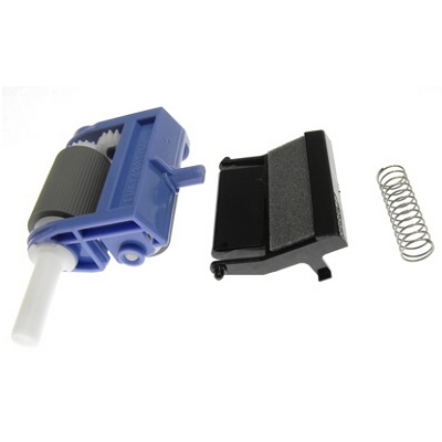
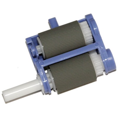
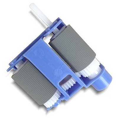
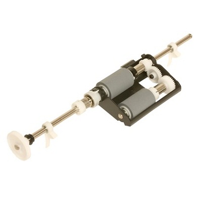
| Деталь: | ROLLER HOLDER SP ASSY |
| Парткод: | LM5852001 |
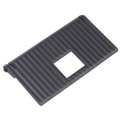
| Деталь: | MP ROLLER HOLDER SP ASSY |
| Парткод: | LM6753001 |
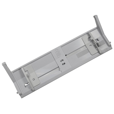
| Деталь: | PAPER TRAY UNIT |
| Парткод: | LU0691001 |

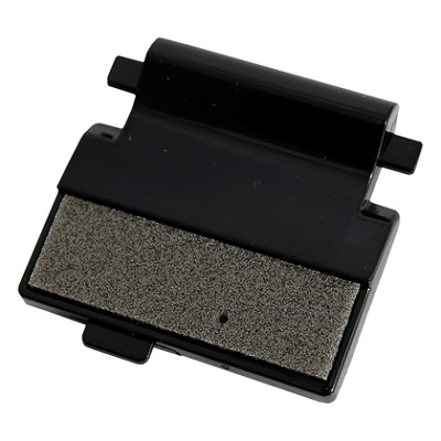
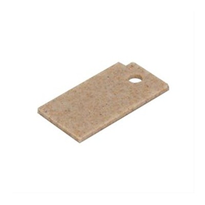
| Деталь: | SEPARATION PAD ASSY |
| Парткод: | LM5237001 |
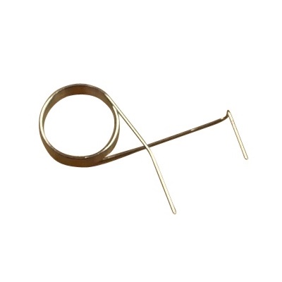
| Деталь: | SEPARATION PAD SPRING |
| Парткод: | LM5239001 |
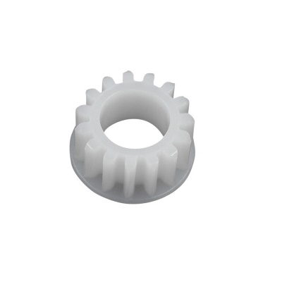
| Деталь: | GEAR 15 |
| Парткод: | LM5245001 |
| Цена: | 80 ₽ |
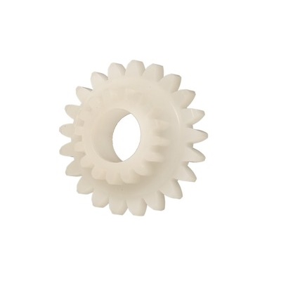
| Деталь: | GEAR 21-16 |
| Парткод: | LM5246001 |
| Цена: | 60 ₽ |
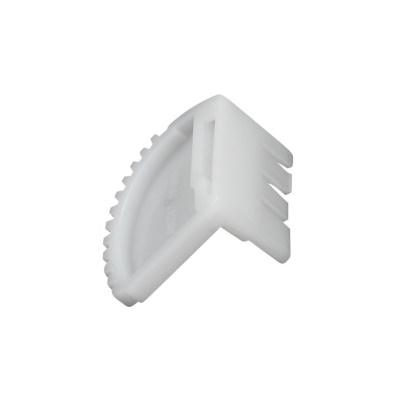
| Деталь: | LIFT GEAR 46 |
| Парткод: | LM5247001 |
| Цена: | 80 ₽ |
| Деталь: | FUSER UNIT 115V (SP) FOR US/CAN/BRA |
| Парткод: | LU0214001 |
| Деталь: | FUSER UNIT 230V (SP) FOR ARG/CHL |
| Парткод: | LU0215001 |
| Деталь: | TAPTITE BIND B M4X16 |
| Парткод: | 85411616 |
| Деталь: | TAPTITE CUP B M4X16 |
| Парткод: | LM5881001 |
| Деталь: | MAIN PCB ASSY, DCP8060 |
| Парткод: | LG6566001 |
| Деталь: | MAIN PCB ASSY, DCP8065DN |
| Парткод: | LG6567001 |
| Цена: | 36 900 ₽ |
| Деталь: | MAIN PCB ASSY, MFC8460N |
| Парткод: | LG6552001 |
| Деталь: | MAIN PCB ASSY, MFC8660DN |
| Парткод: | LG6661001 |
| Деталь: | MAIN PCB ASSY, MFC8860DN/ MFC8670DN FOR US/ CAN |
| Парткод: | LG6563001 |
| Деталь: | MAIN PCB ASSY, MFC8870DW |
| Парткод: | LG6568001 |
| Деталь: | MAIN PCB ASSY, MFC8860DN FOR ARG/ CHL/ BRA |
| Парткод: | LG6563004 |
| Деталь: | NCU PCB ASSY, MFC8460N/ MFC8660DN/ MFC8860DN/ MFC8870DW/ MFC8670DN FOR US |
| Парткод: | LG5925001 |
| Деталь: | NCU PCB ASSY, MFC8460N/ 8860DN/ 8870DW FOR CAN |
| Парткод: | LG5925002 |
| Деталь: | NCU PCB ASSY, MFC8860DN FOR ARG/ CHL |
| Парткод: | LG6190005 |
| Деталь: | NCU PCB ASSY, MFC8860DN FOR BRA |
| Парткод: | LG6190006 |
| Деталь: | BINDER 2.3X79 |
| Парткод: | LJ8657001 |
| Деталь: | PS PCB UNIT, DCP8060/ DCP8065DN/ MFC8460N/ MFC8660DN/ MFC8860DN/ MFC8670DN FOR US/ CAN/ BRA |
| Парткод: | LG6556001 |
| Деталь: | PS PCB UNIT, MFC8870DW |
| Парткод: | LG7176001 |
| Деталь: | PS PCB UNIT, DCP8060 FOR ARG/ CHL |
| Парткод: | LG6623001 |
| Деталь: | PS PCB UNIT, MFC8860DN FOR ARG/ CHL |
| Парткод: | LG7057001 |
| Деталь: | HIGH-VOLTAGE PS PCB ASSY |
| Парткод: | LJ9978001 |
| Цена: | 3 300 ₽ |
| Деталь: | TAPTITE CUP S M3X6 SR |
| Парткод: | LM5867001 |
| Деталь: | BATTERY ASSY, DCP8065DN/ MFC8460N/ MFC8660DN/ MFC8860DN/ MFC8870DW/ MFC8670DN |
| Парткод: | LG5921001 |
| Деталь: | FILTER |
| Парткод: | LM2445001 |
| Деталь: | FAN MOTOR 60 UNIT LV |
| Парткод: | LM5114001 |
| Деталь: | FAN MOTOR 60 UNIT |
| Парткод: | LM5116001 |
| Деталь: | WIRELESS PCB, MFC8870DW |
| Парткод: | LG6846001 |
| Деталь: | MAIN FRAME L UNIT, DCP8060 |
| Парткод: | LF9765001 |
| Деталь: | MAIN FRAME L UNIT, MFC8460N |
| Парткод: | LF9611001 |
| Деталь: | MAIN FRAME L UNIT, DCP8065N/ MFC8660DN/ MFC8860DN/ MFC8670DN/ MFC8870DW |
| Парткод: | LF9727001 |
| Деталь: | GEAR 17 MP ROLLER DRIVE |
| Парткод: | LM5104001 |
| Деталь: | GEAR 20 T1 ROLLER DRIVE |
| Парткод: | LM5103001 |
| Деталь: | DEVELOP JOINT |
| Парткод: | LM4227001 |
| Цена: | 190 ₽ |
| Деталь: | MAIN MOTOR ASSY AL |
| Парткод: | LM5047001 |
| Цена: | 2 500 ₽ |
| Деталь: | FUSER GEAR 39 H/ R DRIVE |
| Парткод: | LM5048001 |
| Цена: | 600 ₽ |
| Деталь: | REGISTER SOLENOID ASSY |
| Парткод: | LM5058001 |
| Деталь: | MP SOLENOID ASSY |
| Парткод: | LM5062001 |
| Цена: | 1 700 ₽ |
| Деталь: | T1 SOLENOID ASSY |
| Парткод: | LM5067001 |
| Деталь: | TONER SENSOR PCB ASSY |
| Парткод: | LJ9935001 |
| Деталь: | PT SENSOR HOLDER |
| Парткод: | UL9037001 |
| Деталь: | RELAY FRONT PCB ASSY |
| Парткод: | LJ9938002 |
| Деталь: | INTERLOCK SW ASSY |
| Парткод: | LJ9940001 |
| Деталь: | RELAY REAR PCB ASSY, DCP8060/ MFC8460N |
| Парткод: | LM9168001 |
| Деталь: | RELAY REAR PCB ASSY,DCP8065DN/ MFC8660DN/ MFC8860DN/ MFC8870DW/ MFC8670DN |
| Парткод: | LJ9942001 |
| Деталь: | NEW TONER ACTUATOR |
| Парткод: | LM5085001 |
| Деталь: | NEW TONER ACTUATOR SPRING |
| Парткод: | LM5086001 |
| Деталь: | RUBBER FOOT |
| Парткод: | LJ7403001 |
| Деталь: | CONNECTOR |
| Парткод: | LJ9945001 |
| Деталь: | EJECTOR SOLENOID, DCP8065DN/ MFC8660DN/ MFC8860DN/ MFC8870DW/ MFC8670DN |
| Парткод: | LM5011001 |
| Деталь: | TAPTITE CUP S M3X6 |
| Парткод: | 87320616 |
| Деталь: | TAPTITE BIND B M3X10 |
| Парткод: | 85311016 |
| Деталь: | TAPTITE BIND B M3x10, DCP8065DN/ MFC8860DN/ MFC8870DW/ MFC8670DN |
| Парткод: | 85311016 |
| Деталь: | THERMISTOR ASSY |
| Парткод: | LG4518001 |
| Деталь: | DEV GEAR 37R JOINT DRIVE |
| Парткод: | LM5043001 |
| Деталь: | JOINT COVER ASSY, GRAY(1581), DCP8060/ DCP8065DN FOR US/ CAN |
| Парткод: | LF9975001 |
| Деталь: | JOINT COVER ASSY PSL, GRAY(1581), DCP8060 FOR ARG/ CHL |
| Парткод: | LS0094001 |
| Деталь: | JOINT COVER ASSY, GRAY(1581), MFC8460N/ MFC8660DN/ MFC8860DN/ MFC8870DW/ MFC8670DN FOR US/ CAN/ BRA |
| Парткод: | LF9619001 |
| Деталь: | JOINT COVER ASSY PSL, GRAY(1581), MFC8860DN FOR ARG/ CHL |
| Парткод: | LS0095001 |
| Деталь: | TAPTITE, BIND B M4X12 |
| Парткод: | 85411216 |
| Деталь: | SPEAKER ASSY |
| Парткод: | LG6529001 |
| Деталь: | DRIVER PCB ASSY |
| Парткод: | LG6531001 |
| Деталь: | SIDE COVER R, GRAY(1736) |
| Парткод: | LF9624001 |
| Деталь: | SIDE COVER L, GRAY(1736) |
| Парткод: | LF9625001 |
| Деталь: | ACCESS COVER , GRAY(1736) |
| Парткод: | LM5273001 |
| Деталь: | REAR COVER |
| Парткод: | LM5274001 |
| Деталь: | OUTER CHUTE ASSY2 EL25 FOR US/ CAN/ BRA |
| Парткод: | LU0277001 |
| Деталь: | OUTER CHUTE ASSY2 EL20 FOR ARG/ CHL |
| Парткод: | LU0278001 |
| Деталь: | DX COVER, DCP8060/ MFC8460N |
| Парткод: | LM5424001 |
| Деталь: | TAPTITE CUP B M3X8 |
| Парткод: | 87310816 |
| Деталь: | BROTHER EMBLEM |
| Парткод: | LM5771001 |
| Деталь: | PROCESS UNIT OP LABEL |
| Парткод: | LM5542001 |
| Деталь: | RELEASE LABEL |
| Парткод: | LM5758001 |
| Деталь: | FUSER CAUTION LABEL |
| Парткод: | LM4639001 |
| Деталь: | PAPER STACK LEVER ASSY AL, DCP8060/ MFC8860DN FOR ARG/ CHL |
| Парткод: | LU0160001 |
| Деталь: | ALFB UNIT ASSY(SP), FOR US/CAN/BRA |
| Парткод: | LP2357001 |
| Деталь: | ALFB UNIT ASSY(SP), FOR ARG/CHL |
| Парткод: | LS0002001 |
| Деталь: | TAPTITE, CUP B M4X20 |
| Парткод: | 87412016 |
| Деталь: | PHOTO INTERRUPTER |
| Парткод: | LG2239001 |
| Деталь: | FFC CABLE ASSY |
| Парткод: | LF9629001 |
| Деталь: | SCANNER MOTOR FB |
| Парткод: | LE8632001 |
| Деталь: | PULLEY ASSY |
| Парткод: | LF9637001 |
| Деталь: | PULLEY SPRING |
| Парткод: | LE8640001 |
| Деталь: | CCD MODULE(SP) |
| Парткод: | LF2037001 |
| Деталь: | BELT |
| Парткод: | LE8642001 |
| Деталь: | TOP COVER ASSY |
| Парткод: | LF9641001 |
| Деталь: | TAPTITE, CUP B M4X12 |
| Парткод: | 87411216 |
| Деталь: | TAPTITE, PAN B M3X8 |
| Парткод: | LE2861001 |
| Деталь: | SCREW, PAN (S/P WASHER) M3X6 |
| Парткод: | 0A4300605 |
| Деталь: | TAPTITE, B 3X6 |
| Парткод: | UF5034001 |
| Деталь: | LOCK LEVER ASSY |
| Парткод: | LF2004001 |
| Деталь: | LOCK LEVER B |
| Парткод: | LE8649001 |
| Деталь: | PANEL UNIT, DCP8060/ DCP8065DN |
| Парткод: | LF9768001 |
| Деталь: | PANEL UNIT, MFC8460N/ MFC8660DN/ MFC8860DN/ MFC8870DW/ MFC8670DN |
| Парткод: | LF9704001 |
| Деталь: | PANEL COVER ASSY, DCP8060 FOR US/ CAN |
| Парткод: | LF9771001 |
| Деталь: | PANEL COVER ASSY, DCP8065DN |
| Парткод: | LF9775001 |
| Деталь: | PANEL COVER ASSY, MFC8460N |
| Парткод: | LF9712001 |
| Деталь: | PANEL COVER ASSY, MFC8660DN |
| Парткод: | LP2407001 |
| Деталь: | PANEL COVER ASSY, MFC8860DN FOR US/ CAN/ ARG/ CHL |
| Парткод: | LF9756001 |
| Деталь: | PANEL COVER ASSY, MFC8870DW |
| Парткод: | LF9778001 |
| Деталь: | PANEL COVER ASSY, DCP8060 FOR ARG/ CHL |
| Парткод: | LP2163001 |
| Деталь: | PANEL COVER ASSY, MFC8860DN FOR BRA |
| Парткод: | LP2061001 |
| Деталь: | PANEL COVER ASSY, MFC8670DN |
| Парткод: | LS1097001 |
| Деталь: | TAPTITE CUP B M4X12 |
| Парткод: | 87411216 |
| Деталь: | WIRELESS EMBLEM, MFC8870DW |
| Парткод: | LP0380001 |
| Деталь: | ADDRESS LABEL, MFC8460N/ MFC8660DN/ MFC8870DW |
| Парткод: | LF9717001 |
| Деталь: | PRINTED RUBBER KEY, DCP8060/ DCP8065DN |
| Парткод: | LF9769001 |
| Деталь: | PRINTED RUBBER KEY, MFC8460N/ MFC8660DN/ MFC8860DN/ MFC8870DW/ MFC8670DN |
| Парткод: | LF9706001 |
| Деталь: | PANEL PCB ASSY, DCP8060/ DCP8065DN |
| Парткод: | LG6547002 |
| Деталь: | LCD |
| Парткод: | LG6549001 |
| Деталь: | BACK LIGHT MODULE |
| Парткод: | LG6550001 |
| Деталь: | LCD COVER |
| Парткод: | LF9709001 |
| Деталь: | ADDRESS LABEL, MFC8460N/ MFC8660DN/ MFC8860DN/ MFC8870DW/ MFC8670DN |
| Парткод: | LF9717001 |
| Деталь: | PE EG SENSOR ASSY |
| Парткод: | LM9001001 |
| Деталь: | PE ACTUATOR |
| Парткод: | LU0684001 |

| Деталь: | EDGE ACTUATOR |
| Парткод: | LM5132001 |
| Цена: | 170 ₽ |
| Деталь: | EDGE ACTUATOR SPRING |
| Парткод: | LM5133001 |
| Деталь: | ROLLER HOLDER ASSY |
| Парткод: | LM5140001 |
| Деталь: | REGIST ACTUATOR FRONT |
| Парткод: | LM5150001 |
| Цена: | 80 ₽ |
| Деталь: | REGIST ACTUATOR REAR |
| Парткод: | LM5151001 |
| Цена: | 80 ₽ |
| Деталь: | REGIST ACTUATOR SPRING |
| Парткод: | LM5152001 |
| Цена: | 30 ₽ |
| Деталь: | MP PE SENSOR ASSY |
| Парткод: | LJ9999001 |
| Деталь: | MP ROLLER HOLDER ASSY |
| Парткод: | LM5165001 |
| Деталь: | PE ACTUATOR MP |
| Парткод: | LM5171001 |
| Деталь: | PE ACTUATOR MP B 2 |
| Парткод: | LU0027001 |
| Деталь: | MP SEPARATION SPRING |
| Парткод: | LM6490001 |
| Деталь: | SEPARATION PAD ASSY MP |
| Парткод: | LM6752001 |
| Деталь: | BINDER 2.3X79 |
| Парткод: | LJ8657001 |
| Деталь: | TRAY MP ASSY |
| Парткод: | LM5196001 |
| Цена: | 900 ₽ |
| Деталь: | MP TRAY COVER ASSY |
| Парткод: | LF9617001 |
| Деталь: | PROCESS COVER ASSY |
| Парткод: | LM5205001 |
| Деталь: | TAPTITE BIND B M3X8 |
| Парткод: | 85310816 |
| Деталь: | PROCESS COVER STOPPER |
| Парткод: | LM5124001 |
| Деталь: | SUPPORT FLAP |
| Парткод: | LM5208001 |
| Цена: | 320 ₽ |
| Деталь: | TAPTITE CUP B M4X10 |
| Парткод: | 87411016 |
| Деталь: | TONER LED PCB ASSY |
| Парткод: | LM9022001 |
| Деталь: | LED HOLDER |
| Парткод: | LM4267001 |
| Деталь: | RUBBER FOOT |
| Парткод: | LJ7403001 |
| Деталь: | ADF CHUTE ASSY, DCP8060/ MFC8460N/ MFC8660DN |
| Парткод: | LF9650001 |
| Деталь: | ADF CHUTE ASSY, DCP8065DN/ MFC8860DN/ MFC8870DW/ MFC8670DN |
| Парткод: | LF9730001 |
| Деталь: | ADF MOTOR |
| Парткод: | LE8688001 |
| Деталь: | S/ B SOLENOID ASSY, DCP8065DN/ MFC8860DN/ MFC8870DW/ MFC8670DN |
| Парткод: | LP2353001 |
| Деталь: | PF SOLENOID ASSY, DCP8065DN/ MFC8860DN/ MFC8870DW/ MFC8670DN |
| Парткод: | LP2354001 |
| Деталь: | ADF RELAY PCB, DCP8060/ MFC8460N/ MFC8660DN |
| Парткод: | LG6537001 |
| Деталь: | ADF RELAY PCB, DCP8065DN/ MFC8860DN/ MFC8870DW/ MFC8670DN |
| Парткод: | LG6537002 |
| Деталь: | UPPER MAIN CHUTE ASSY |
| Парткод: | LF9666001 |
| Деталь: | LOWER MAIN CHUTE ASSY, DCP8060/ MFC8460N/ MFC8660DN |
| Парткод: | LF9669001 |
| Деталь: | LOWER MAIN CHUTE ASSY, DCP8065DN/ MFC8860DN/ MFC8870DW/ MFC8670DN |
| Парткод: | LF9741001 |
| Деталь: | EXIT ROLLER ASSY |
| Парткод: | LF9673001 |
| Деталь: | LF ROLLER3 ASSY |
| Парткод: | LF9675001 |
| Деталь: | LF ROLLER4 ASSY |
| Парткод: | LF9677001 |
| Деталь: | FLAP ASSY, DCP8065DN/ MFC8860DN/ MFC8870DW/ MFC8670DN |
| Парткод: | LF9743001 |
| Деталь: | PAPER FEED CHUTE ASSY, DCP8060/ MFC8460N/ MFC8660DN |
| Парткод: | LF9681001 |
| Деталь: | PAPER FEED CHUTE ASSY, DCP8065DN/ MFC8860DN/ MFC8870DW/ MFC8670DN |
| Парткод: | LF9747001 |
| Деталь: | EXIT CHUTE COVER ASSY |
| Парткод: | LF9692001 |
| Деталь: | LF ROLLER1 ASSY |
| Парткод: | LP2448001 |
| Деталь: | PF ROLLER HOLDER ASSY |
| Парткод: | LS1030001 |
| Цена: | 3 100 ₽ |
| Деталь: | SB ROLLER ASSY, DCP8065DN/ MFC8860DN/ MFC8870DW/ MFC8670DN |
| Парткод: | LF9749001 |
| Деталь: | SB CHUTE ASSY, DCP8065DN/ MFC8860DN/ MFC8870DW/ MFC8670DN |
| Парткод: | LF9751001 |
| Деталь: | TAPTITE CUP S M3X8 SR |
| Парткод: | LP2378001 |
| Деталь: | TAPTITE CUP B M3X10 |
| Парткод: | 87311016 |
| Деталь: | SX CHUTE, DCP8060/ MFC8460N/ MFC8660DN |
| Парткод: | LF9850001 |
| Деталь: | LF4 FILM |
| Парткод: | LP2347001 |
| Деталь: | SCREW PAN (S/ P WASHER) M3X6 |
| Парткод: | 0A4300605 |
| Деталь: | LF ROLLER2 ASSY |
| Парткод: | LS0761001 |
| Деталь: | ACTUATOR R |
| Парткод: | LF9671001 |
| Деталь: | ACTUATOR SB, DCP8065DN/ MFC8860DN/ MFC8870DW/ MFC8670DN |
| Парткод: | LF9742001 |
| Деталь: | PHOTO INTERRUPTER |
| Парткод: | LG2239001 |
| Деталь: | PHOTO INTERRUPTER, DCP8065DN/ MFC8860DN/ MFC8870DW/ MFC8670DN |
| Парткод: | LG2239001 |
| Деталь: | ACTUATOR FRONT1 |
| Парткод: | LF9683001 |
| Деталь: | ACTUATOR FRONT2, DCP8065DN/ MFC8860DN/ MFC8870DW/ MFC8670DN |
| Парткод: | LF9748001 |
| Деталь: | SEPARATION SPRING |
| Парткод: | LF9684001 |
| Деталь: | RUBBER HOLDER |
| Парткод: | LF9685001 |
| Деталь: | SEPARATION RUBBER |
| Парткод: | LF9686001 |
| Цена: | 700 ₽ |
| Деталь: | SPRING PLATE ADF FRONT A ASSY |
| Парткод: | LE1513001 |
| Деталь: | ADF FILM |
| Парткод: | LE2470001 |
| Деталь: | PRESSURE ROLLER |
| Парткод: | LP2159001 |
| Деталь: | LF SPRING |
| Парткод: | LE2472001 |
| Деталь: | BACK SHEET ADF |
| Парткод: | LP2907001 |
| Деталь: | ADF UNIT LGL(SP), DCP8060 FOR US, MFC8460N/ MFC8660D N |
| Парткод: | LP2363001 |
| Деталь: | ADF UNIT LGL(SP), DCP8060 FOR ARG/ CHL |
| Парткод: | LS0026001 |
| Деталь: | ADF UNIT LGL(SP), MFC8860DN FOR US/ CAN/ BRA, DCP8065DN/ MFC8870DW/ MFC8670DN |
| Парткод: | LP2329001 |
| Деталь: | ADF UNIT LGL(SP), MFC8860DN FOR ARG/ CHL |
| Парткод: | LS0003001 |
| Деталь: | HINGE ASSY L |
| Парткод: | LF9703001 |
| Деталь: | TAPTITE CUP B M3X10 |
| Парткод: | 87311016 |
| Деталь: | HINGE BASE R |
| Парткод: | LE6244001 |
| Деталь: | TAPTITE BIND B M4X12 |
| Парткод: | 85411216 |
| Деталь: | DOCUMENT COVER LGL SUB ASSY |
| Парткод: | LF9644001 |
| Деталь: | TAPTITE CUP S M3X8 SR |
| Парткод: | LP2378001 |
| Деталь: | ADF SIDE COVER F |
| Парткод: | LF9696001 |
| Деталь: | ADF SIDE COVER R |
| Парткод: | LF9697001 |
| Деталь: | ADF COVER ASSY, DCP8060/ MFC8460N/ MFC8660DN |
| Парткод: | LF9700001 |
| Деталь: | ADF COVER ASSY, DCP8065DN/ MFC8860DN/ MFC8870W/ MFC8670DN |
| Парткод: | LF9754001 |
| Деталь: | DOCUMENT HOLD ASSY |
| Парткод: | LE8834001 |
| Деталь: | DOCUMENT HOLD SPRING |
| Парткод: | LF2026001 |
| Деталь: | TAPTITE CUP B M3X10 |
| Парткод: | LP2320001 |
| Деталь: | ADF HARNESS ASSY ALFB DX, DCP8065DN/ MFC8860DN/ 8870DW/ MFC8670DN FOR US/ CAN/ BRA |
| Парткод: | LG6545001 |
| Деталь: | ADF HARNESS ASSY ALFB DX, MFC8860DN FOR ARL/ CHL |
| Парткод: | LG7199001 |
| Деталь: | ADF HARNESS ASSY ALFB SX, DCP8060/ MFC8460N/ 8660DN FOR US/ CAN |
| Парткод: | LG6575001 |
| Деталь: | ADF HARNESS ASSY ALFB SX, DCP8060 FOR ARG/ CHL |
| Парткод: | LT0007001 |
| Деталь: | DOCUMENT EJECTION TRAY |
| Парткод: | LF9647001 |
| Деталь: | DOCUMENT COVER SENSOR |
| Парткод: | LG3218001 |
| Деталь: | PRESSER ROLLER |
| Парткод: | UF9009001 |
| Деталь: | EJECTION ROLLER B4 |
| Парткод: | UL6244002 |
| Деталь: | HINGE ARM R |
| Парткод: | LE6245001 |
| Деталь: | TAPTITE, CUP B M3X10 |
| Парткод: | 87311016 |
Коды ошибок
56
57
5A
5B
5C
5D
60
68
69
6A
6B
6C
6E
6F
71
72
73
74
75
76
77
78
79
7A
7B
7D
80
81
82
83
84
85
86
88
8A
8B
8C
A1
A2
A3
A4
A5
A6
AA
AC
AF
B1
B2
B3
B4
B5
B6
B7
B8
B9
BB
BD
BE
BF
D0 … DF
E6
E8
EA
Описание
| Error code: | 56 |
| Display: | Toner Empty |
| Description: | The toner cartridge has run out. The machine stops printing. |
| Causes: | Harness connection failure of back cover switch ASSY. Eject actuator failure. Eject sensor PCB ASSY failure. Main PCB failure |
| Remedy: | Replace the toner cartridge with a new one. |
| Error code: | 57 |
| Display: | Toner Low |
| Description: | The toner cartridge is almost empty. |
| Remedy: | Take out the toner cartridge and thoroughly shake it. By doing this, you can temporarily reestablish printing operations. |
| Error code: | 5A |
| Display: | Unable to print 5A |
| Description: | HVPS PCB failure (Developing bias voltage failure) |
| Causes: | HVPS PCB ASSY harness connection failure. HVPS PCB failure. Main PCB failure |
| Remedy: | 1 HVPS PCB ASSY harness connection failure Check the harness connection between the HVPS PCB and main PCB. Then, reconnect them. 2 HVPS PCB failure Replace the HVPS PCB ASSY. 3 Main PCB failure Replace the main PCB ASSY. |
| Error code: | 5B |
| Display: | Unable to print 5B |
| Description: | New toner detection lever malfunction |
| Causes: | New toner detection switch harness connection failure. New toner detection switch failure. Main PCB failure |
| Remedy: | 1 New toner detection switch harness connection failure Check the harness connection of the new toner detection switch. Then, reconnect it. 2 New toner detection switch failure Replace the new toner harness ASSY. 3 Main PCB failure Replace the main PCB ASSY. |
| Error code: | 5C |
| Description: | It was detected that the size of the paper was less than the specified value. |
| Causes: | 1 Engine PCB failure. 2 Main PCB failure. |
| Remedy: | 1 Engine PCB failure Replace the engine PCB ASSY. 2 Main PCB failure Replace the main PCB ASSY. |
| Error code: | 5D |
| Display: | Unable to print 5D |
| Description: | Overcurrent protection was activated in the driver IC during Purge cam operation. |
| Causes: | The driving current has exceeded the limit due to an abnormal load applied to the maintenance unit. |
| Remedy: | 1 Foreign materials in the Maintenance unit part Remove foreign materials. 2 Maintenance unit defective Replace the Maintenance unit. 3 Main PCB defective Replace the Main PCB ASSY. |
| Error code: | 60 |
| Display: | Nongenuine Toner |
| Description: | Imaging Unit Motor Failure, Code 60 |
| Causes: | • Imaging Unit Drive Motor • Engine Control Board |
| Remedy: | 1 1. Enter service diagnostics and run the Imaging Unit Motor test. 2. Does the motor operate correctly? Go to step 7. Go to step 2. 2 1. Is the voltage at J210-5 +5 VDC? Go to step 3. Replace the engine control board. 3 1. Is the voltage at J210-7 +24 VDC? Go to step 4. Use the +24 VDC wirenets to troubleshoot and resolve the missing voltage. 4 1. Enter service diagnostics. 2. While running the Imaging Unit Motor test, check the voltage at J210-1 and J210-2. 3. Is the voltage 0 VDC while the test is running? Go to step 5. Replace the engine control board. 5 Is the frequency between J210-4 and ground between 1 KHz and 1.3 KHz? Replace the imaging unit drive motor. Go to step 6. 6 1. Check for a short to ground at J210-4. 2. Is the wire grounded? Repair or replace the wiring harness. Replace the engine control board. 7 1. Enter service diagnostics. 2. While running the Imaging Unit Motor test, check the voltage at J210-9. 3. Is the voltage +5 VDC while the test is running? Replace the imaging unit drive motor. Replace the engine control board. |
| Error code: | 68 |
| Display: | TOP FAN MOTOR LOCK ERROR |
| Description: | Orange light on An error has occurred at the top fan. |
| Causes: | Fuser unit harness connection failure. Fuser unit failure. LVPS PCB unit failure. Main PCB failure. |
| Remedy: | 1) Check the harness connected between the Engine controller and the exit board. (If the harness is out, insert it to the connector.) 2) Check the harness connected between the exit board and the top fan. (If the harness is out, insert it to the connector.) 3) In the Engine diagnostic mode, operate the top fan to check the fan is operating. (If it is not operating, replace the top fan.) 4) Check the No. 1 pin of the exit board whether 24V is outputted and check the D5 whether it is normal. (If 24V is not outputted or the part is abnormal, replace the exit board.) 5) Replace the Engine controller. |
| Error code: | 69 |
| Display: | Sleep Mode |
| Description: | Sleep Mode |
| Causes: | It means that the printer fuser is turned off, and the power consumption is minimized. |
| Remedy: | 1) Check the harness connected between the Engine controller and the paper size board. (If the harness is out, insert it to the connector.) 2) In the Engine diagnostic mode, operate the MPF trans sensor to check if it is operating. (If it is not operating, replace the paper size board.) 3) Replace the MPF transfer. |
| Error code: | 6A |
| Description: | Fuser unit failure (The side thermistor does not detect 60°C within the specified time.) |
| Causes: | Fuser unit harness connection failure. Fuser unit failure. LVPS PCB unit failure. Main PCB failure. |
| Remedy: | 1 Fuser unit harness connection failure Check the harness connection of the fuser unit and reconnect it. 2 Fuser unit failure Replace the fuser unit. 3 LVPS PCB unit failure Replace the LVPS PCB unit. 4 Main PCB failure Replace the main PCB ASSY. |
| Error code: | 6B |
| Description: | Fuser unit failure (The center thermistor does not detect 100°C within the specified time.) |
| Causes: | Fuser unit harness connection failure. Fuser unit failure. LVPS PCB unit failure. Main PCB failure. |
| Remedy: | 1 Fuser unit harness connection failure Check the harness connection of the fuser unit and reconnect it. 2 Fuser unit failure Replace the fuser unit. 3 LVPS PCB unit failure Replace the LVPS PCB unit. 4 Main PCB failure Replace the main PCB ASSY. |
| Error code: | 6C |
| Display: | Unable to Print 6C |
| Description: | Fuser unit failure (The center thermistor detects higher temperature than the specified value.) |
| Causes: | Fuser unit harness connection failure. Fuser unit failure. LVPS PCB unit failure. Main PCB failure. |
| Remedy: | 1 Fuser unit harness connection failure Check the harness connection of the fuser unit and reconnect it. 2 Fuser unit failure Replace the fuser unit. 3 LVPS PCB unit failure Replace the LVPS PCB unit. 4 Main PCB failure Replace the main PCB ASSY. |
| Error code: | 6E |
| Description: | Fuser unit failure (The center thermistor does not detect temperature rising within the specified time.) |
| Causes: | Fuser unit harness connection failure. Fuser unit failure. LVPS PCB unit failure. Main PCB failure. |
| Remedy: | 1 Fuser unit harness connection failure Check the harness connection of the fuser unit and reconnect it. 2 Fuser unit failure Replace the fuser unit. 3 LVPS PCB unit failure Replace the LVPS PCB unit. 4 Main PCB failure Replace the main PCB ASSY. |
| Error code: | 6F |
| Display: | Unable to Print 6F |
| Description: | Fuser unit failure (The center and side thermistors detect extremely high temperature.) |
| Causes: | Fuser unit harness connection failure. Fuser unit failure. LVPS PCB unit failure. Main PCB failure. |
| Remedy: | 1 Fuser unit harness connection failure Check the harness connection of the fuser unit and reconnect it. 2 Fuser unit failure Replace the fuser unit. 3 LVPS PCB unit failure Replace the LVPS PCB unit. 4 Main PCB failure Replace the main PCB ASSY. |
| Error code: | 71 |
| Display: | Paper Jam 0 |
| Description: | Paper Jam 0 |
| Causes: | The front part of paper is jammed between pickup unit and Feed sensor. |
| Error code: | 72 |
| Display: | Paper Jam 1 |
| Description: | Engine Firmware Failure The Engine Control Board detected a firmware error. |
| Causes: | • Engine Control Board, Pl9.1.16 • EEPROM Board, PL9.1.12 |
| Remedy: | 1 Cycle printer power. Does the error persist? Go to Step 2. Complete 2 Is P/J144 on the EEPROM Board properly seated and defect free? Go to Step 3. Reseat P/J144 or replace the EEPROM Board. 3 Turn printer power off and then back on. Does the error persist? Replace the Engine Control Board. Complete |
| Error code: | 73 |
| Display: | Paper Jam 2 |
| Description: | Paper Jam 2 |
| Causes: | The front part of paper is jammed just after passing through the discharge sensor. |
| Error code: | 74 |
| Display: | [TRAY x] [PAPER SIZE] EMPTY |
| Description: | F/W Overrun detect |
| Causes: | · Loose cable connection · Defective cleaner clutch · Defective IOD2 board · Defective IOD1 board · Defective MCTL board |
| Remedy: | 1) Check the harness connected between the Engine controller and the TA board. (If the harness is out, insert it to the connector.) 2) Check the harness connected between the TA board and the Pickup unit. (If the harness is out, insert it to the connector.) 3) Check the harness connected between the Pickup unit and the cassette sensing board. (If the harness is out, insert it to the connector.) 4) Check the pickup unit. (If it is inferior part or warped part, replace it.) 5) Check the damage of the cassette sensing B . (If it is damaged, replace the cassette sensing board.) 6) In the Engine diagnostic mode, operate the running count of the paper if it is under 39. (If it is over 39, replace the Pickup unit.) 7) Replace the TA board. |
| Error code: | 75 |
| Display: | [TRAY x] NOT INSTALLED |
| Description: | VIC Limutter |
| Causes: | · Loose cable connection · Defective fusing unit clutch · Defective IOD2 board · Defective MCTL board |
| Remedy: | 1) Check for any warping or damage to the cassette (In the case of warping or damage, replace the cassette) |
| Error code: | 76 |
| Display: | Out Bin Full |
| Description: | Fuser Firmware Failure A failure was detected in the Fuser Firmware. |
| Causes: | • Fuser, PL5.1.1 • FSR/ADC Harness, PL5.2.28 • Engine Control Board, PL9.1.16 |
| Remedy: | 1 Check the Fuser for damage. Is the Fuser damaged? Replace the Fuser. Go to Step 2. 2 Check the Fuser connection for damage. Any broken or bent pins? Repair or replace the parts. Go to Step 3. 3 Replace the Fuser. Does the error persist? Go to Step 4. Complete 4 Check all pins on the FSR/ADC Harness PL5.2.28 for continuity. 1. Disconnect P/J36 and P/J361. 2. Check continuity between J36 <=> J361. Replace the Engine Control Board. Replace the FSR/ ADC Harness. |
| Error code: | 77 |
| Display: | WAIT IMAGE |
| Description: | Image Density Failure The engine detected a low-density image condition. |
| Causes: | • Transfer Roller, PL5.1.4 • CTD (ADC) Sensor PL5.2.19 • Engine Control Board PL9.1.16 • FSR/ADC Harness PL5.2.28 |
| Remedy: | 1 Clean the CTD (ADC) Sensor. Does the error persist? Go to Step 2. Complete 2 Check the following for evidence of fault or damage: Transfer Roller Assembly, PL5.1.4 CTD (ADC) Sensor, PL5.2.19 Replace any damaged parts. Go to Step 3. 3 Check the CTD (ADC) Sensor connector. Is P/J136 connected to the harness? Go to Step 4. Reseat the connector to the sensor. 4 Replace the CTD (ADC) Sensor. Does the error persist? Go to Step 5. Complete 5 Check all pins on the FSR/ADC Harness PL5.2.28 for continuity. 1. Disconnect P/J36 and P/J136 2. Check continuity between J36 <=> J136 Replace the Engine Control Board Replace the FSR/ ADC Harness. |
| Error code: | 78 |
| Display: | WRONG PAPER SIZE [PAPER] IN [TRAY x] |
| Description: | Waste Cartridge Full Detection Sensor Failure, Code 78 |
| Causes: | • Waste Cartridge • Waste Cartridge Full Sensor • Engine Control Board |
| Remedy: | 1 1. Remove the waste cartridge sensor holder without disconnecting the harnesses. 2. Measure the voltage between the yellow wire on the waste cartridge full sensor and frame ground, alternately interrupting the sensor. 3. Does the voltage toggle between +5 and 0 VDC? Go to step 5. Go to step 2. 2 1. Measure the voltage between the gray wire and frame ground. 2. Does the voltage measure +5 VDC? Go to step 4. Go to step 3. 3 1. Remove the rear cover and rear shield. 2. Measure the voltage at J407B-17 on the engine control board. 3. Does the voltage measure +5 VDC? Inspect the wiring harness for damage and replace, if necessary. Replace the engine control board. 4 1. Measure the voltage between the violet wire and frame ground. 2. Does the voltage measure 0 VDC? Replace the waste cartridge full sensor. Inspect the wiring harness for damage and replace, if necessary. 5 1. Remove the rear cover and rear shield. 2. Measure the voltage at J407B-16 on the engine control board. 3. Alternately interrupt the sensor 4. Does the voltage toggle between +5 and 0 VDC? Replace the engine control board. Inspect the wiring harness for damage and replace, if necessary. |
| Error code: | 79 |
| Display: | 79 |
| Description: | No detection of the internal temperature thermistor. |
| Causes: | Harness connection failure of internal temperature thermistor. Internal temperature thermistor failure. Main PCB failure |
| Remedy: | 1 Harness connection failure of internal temperature thermistor Check the harness connection of the internal temperature thermistor, and reconnect it. 2 Internal temperature thermistor failure Replace the internal temperature thermistor. 3 Main PCB failure Replace the main PCB ASSY. |
| Error code: | 7A |
| Display: | Unable to clean 7A |
| Description: | No detection of the main motor lock signal. |
| Causes: | Main motor failure. Main PCB failure. |
| Remedy: | 1 Main motor failure Replace the main motor ASSY. 2 Main PCB failure Replace the main PCB ASSY. |
| Error code: | 7B |
| Display: | Unable to clean 7B |
| Description: | Main PCB failure |
| Causes: | Main PCB failure |
| Remedy: | 1 Main PCB failure Replace the main PCB ASSY. |
| Error code: | 7D |
| Display: | Unable to clean 7D |
| Description: | Dirt on drum unit |
| Causes: | Dirt or dust on drum unit electrodes. HVPS PCB failure. Main PCB failure. |
| Remedy: | 1 Dirt or dust on drum unit electrodes Clean the electrodes on the drum unit. ( p.271 "Electrodes location on the drum unit") 2 HVPS PCB failure Replace the HVPS PCB ASSY. 3 Main PCB failure Replace the main PCB ASSY. |
| Error code: | 80 |
| Display: | ERROR 80 FORMAT |
| Description: | Engine Logic Board Failure, Code 80 |
| Remedy: | 1. Cycle power to the printer to clear the error. 2. Did this clear the error? Complete Replace the engine control board or the image processor board. |
| Error code: | 81 |
| Display: | 81 |
| Description: | Controller to Engine Communications Failure, Code 81 |
| Remedy: | 1. Cycle power to the printer to clear the error. 2. Turn the printer off. 3. Remove the Image processor board, IP board cover and metal cover. 4. Inspect the orange ribbon cable between the relay board and the engine control board. 5. Is the connector fully seated and free from damage? Replace in the following order: • Image processor board • Electrical chassis assembly • Engine control board |
| Error code: | 82 |
| Display: | h`******** |
| Description: | Engine Logic Board RAM/ROM Failure, Code 82 |
| Remedy: | 1. Cycle power to the printer to clear the error. 2. Did this clear the error? Complete. Replace the engine control board. |
| Error code: | 83 |
| Display: | h`******** |
| Description: | Engine Logic Board NVRAM Failure, Code 83 |
| Remedy: | 1. Cycle power to the printer to clear the error. 2. Did this clear the error? Complete. Replace in the following order: • engine control board • image processor board |
| Error code: | 84 |
| Display: | h`******** |
| Description: | Controller to Engine Logic Board Time Failure, Code 84 |
| Remedy: | 1. Cycle power to the printer to clear the error. 2. Did this clear the error? Complete. Replace the engine control board. |
| Error code: | 85 |
| Display: | ROM HASH |
| Description: | Engine Logic Board Micro Pitch Failure, Code 85 |
| Remedy: | 1. Cycle power to the printer to clear the error. 2. Did this clear the error? Complete. Replace in the following order: • engine control board • image processor board |
| Error code: | 86 |
| Description: | High-Voltage Power Supply Failure, Code 86 |
| Remedy: | 1. Cycle power to the printer to clear the error. 2. Did this clear the error? Complete. Replace in the following order: • T3 HVPS • image processor board |
| Error code: | 88 |
| Display: | Paper Jam |
| Description: | Lower Tray Communication Failure, Code 88 |
| Causes: | • Engine Control Interface Board • Tray module board • Engine Control board |
| Remedy: | 1 Is J668-1 on the tray module board +5 VDC? Go to step 2. Use the wirenets to troubleshoot and repair the open wire. 2 Is J668-3 on the tray module board +24 VDC? Go to step 3. Use the wirenets to troubleshoot and repair the open wire. 3 1. Check the following connectors for continuity: • P669-1 to J534A-15 • P669-2 to J534A-14 • P669-3 to J534A-13 • P669-4 to J534A-12 • P669-5 to J534A-11 • P669-6 to J534A-10 2. Do all checks indicate continuity? Replace in the following order: • engine control interface board • tray module board • engine control board Check and repair broken wires or bad connectors. |
| Error code: | 8A |
| Display: | Paper Jam |
| Description: | Paper jam in Tray 1 (T1) (It is detects by the registration front sensor) |
| Causes: | Harness connection failure of registration front sensor PCB ASSY. Paper feed roller worn out. Registration front sensor PCB failure. Main PCB failure. |
| Remedy: | 1 Harness connection failure of registration front sensor PCB ASSY Check the harness connection of the registration front sensor PCB ASSY in the appropriate tray, and reconnect it. 2 Paper feed roller worn out Replace the paper feed roller. 3 Registration front sensor PCB failure Check the sensor performance following the procedure ( p.183 "Operational Check of Sensors (Function code 32)"). If any problem occurs, replace the registration front sensor PCB ASSY. 4 Main PCB failure Replace the main PCB ASSY. |
| Error code: | 8B |
| Display: | Unable to Print 8B |
| Description: | Paper jam in Tray 2 |
| Causes: | Dirt on edge sensor. Harness connection failure of high voltage power supply PCB ASSY. Paper feeding kit worn out (MP/ Tray 1/ Tray 2). Registration front sensor failure. Main PCB failure |
| Remedy: | Clean the edge sensor. Check the harness connection of the high voltage power supply PCB ASSY in the appropriate tray, and reconnect it. Replace the paper feeding kit of the appropriate tray. Procedure described in "4.10 Sensor Operational Check (Function code 32)" in Chapter 6. If any problem occurs, replace the high voltage power supply PCB ASSY. Replace the main PCB ASSY. |
| Error code: | 8C |
| Display: | Paper Jam |
| Description: | Paper jam in MP Tray |
| Causes: | Dirt on edge sensor. Harness connection failure of high voltage power supply PCB ASSY. Paper feeding kit worn out (MP/ Tray 1/ Tray 2). Registration front sensor failure. Main PCB failure |
| Remedy: | Clean the edge sensor. Check the harness connection of the high voltage power supply PCB ASSY in the appropriate tray, and reconnect it. Replace the paper feeding kit of the appropriate tray. Procedure described in "4.10 Sensor Operational Check (Function code 32)" in Chapter 6. If any problem occurs, replace the high voltage power supply PCB ASSY. Replace the main PCB ASSY. |
| Error code: | A1 |
| Display: | Cover is Open |
| Description: | Jam at Door A |
| Causes: | • Tray 1 (MPT) Feed Roller, PL10.1.53 • Tray 1 (MPT) Pick Roller, PL10.1.43 • Tray 1 (MPT) Retard Roller, PL10.1.16 • Registration Clutch #1, PL8.1.85 • Tray 2 Registration Motor, PL4.2.36 • Tray 2 Feed Motor, PL4.2.35 • Front Sensor Board, PL4.2.97 |
| Remedy: | 1 Check the following for evidence of fault, dirt, debris, or damage: • Tray 1 (MPT) Feed Rollers • Registration Rollers • Sensor Actuator Is there any damage or debris? Clean or replace the appropriate parts. Go to Step 2. 2 Test the Registration #1 Sensor. Run the Service Diagnostics Registration Entrance Sensor test. Does the sensor operate correctly? Go to Step 3. Replace the actuator. If the error persists, replace the Front Sensor Board. 3 Test the Feed Motor, Registration Motor, and Registration Clutch #1. Do the components function correctly? Replace the Engine Control Board. Go to Step 4. 4 Check the harness for each motor and clutch. Are the wiring harnesses properly connected and free from defects? Replace the Engine Control Board. Replace the wiring harness and/or the problem motor/ clutch. |
| Error code: | A2 |
| Display: | DOCUMENT JAM |
| Description: | Jam at Door A |
| Causes: | • Duplex Unit, PL16.1.0 |
| Remedy: | 1 Check the following for evidence of fault, dirt, debris, or damage: • Door A • Door D • Duplex Unit Rollers • Duplex Unit connector • Duplex Sensors and Actuators Is there any damage or debris? Clean or replace the appropriate parts. Go to Step 2. 2 Test the Duplex Unit sensors. Run the Service Diagnostics for each of the four Duplex Unit sensors. Do the sensors and actuators function correctly Go to Step 3. Replace the damaged sensor. 3 Test the Duplex Unit motors. Run the Service Diagnostics Duplex Motor tests. Do the motors function correctly Go to Step 4. Replace the Duplex Unit 4 Inspect the wiring harness for the Duplex Unit. Is the wiring harness properly connected and free from defects? Replace the Duplex Unit. Replace the Engine Control Board. |
| Error code: | A3 |
| Display: | DOCUMENT JAM |
| Description: | Jam at Door A Misfeed at Tray 1 (MPT) Media reached the Duplex Reverse Sensor, but a second sheet was detected entering the feed path from Tray 1 (MPT). This error represents a misfeed jam for media fed from Tray 1 (MPT). |
| Causes: | • Tray 1 (MPT) Feed Roller, PL10.1.53 • Tray 1 (MPT) Pick Roller, PL10.1.43 • Tray 2 Registration Motor, PL4.2.36 • Tray 2 Feed Motor, PL4.2.35 • Front Sensor Board, PL4.2.97 |
| Remedy: | 1 Check the following for evidence of fault, dirt, debris, or damage: • Tray 1 (MPT) Feed Rollers • Registration Rollers • Sensor Actuator Is there any damage or debris? Clean or replace the appropriate parts. Go to Step 2. 2 Test the Registration #1 Sensor. Run the Service Diagnostics Registration Entrance Sensor test. Does the sensor operate correctly? Go to Step 3. Replace the actuator. If the error persists, replace the Front Sensor Board. 3 Test the Feed Motor, Registration Motor, and Registration Clutch #1. Do the components function correctly? Replace the Engine Control Board. Go to Step 4. 4 Check each motor and clutch harness. Are the harnesses properly connected and free from defects? Replace the Engine Control Board. Replace the harness and/or problem motor/ clutch. |
| Error code: | A4 |
| Display: | Cover is Open |
| Description: | Sorter problem |
| Causes: | • Defective engine gate array • Defective fuse cut circuit on the engine board |
| Remedy: | Correct catching of the ADF cover open sensor. Replace the ADF cover. Replace the ADF cover open sensor. Replace the ADF relay PCB ASSY. Replace the main PCB ASSY. |
| Error code: | A5 |
| Display: | Unable to Scan A5 |
| Description: | ADF interlock |
| Causes: | Scanning failure. |
| Remedy: | 1 Scanning failure Turn the power switch off and on. Then, try scanning again. |
| Error code: | A6 |
| Display: | A6-Bypass Feeder Jam |
| Description: | Paper did not exit the Multi-sheet Bypass Feeder properly, causing a paper jam. Open Cover A and refer to the labels on the printer to clear the jam. |
| Causes: | FB unit failure. Main PCB failure. |
| Remedy: | 1. Ensure the correct weight and type of paper is loaded in the feeder. Also ensure the paper is loaded correctly in the feeder. 2. Clean the bypass feeder’s pick roller. 3. Test the main feed motor as described in “Motor and clutch tests”. Replace the main feed motor. 5. Replace the engine controller board. |
| Error code: | AA |
| Description: | Toner Cartridge Drive motor (sleeve motor) is not phase-locked and is not rotating at normal speed. |
| Causes: | Toner Cartridge Drive motor (sleeve motor) unlocked |
| Remedy: | Replace the main PCB ASSY. |
| Error code: | AC |
| Display: | Unable to Scan AC |
| Description: | OPC home and IT home are not synchronous. |
| Causes: | OPC asynchronous with intermediate transfer unit |
| Remedy: | 1 White level data failure Carry out maintenance 55 to obtain white level data. 2 White reference tape of document pressure bar of ADF cover stained Clean the white reference tape of document pressure bar of ADF cover. 3 Second side CIS unit defective Replace the second side CIS unit. 4 White reference tape of document pressure bar of ADF cover damage, broken Replace the ADF cover. 5 Main PCB defective Replace the main PCB ASSY. |
| Error code: | AF |
| Display: | Unable to Scan AF |
| Description: | FB unit home position failure |
| Causes: | FB unit failure. Main PCB failure. |
| Remedy: | 1 FB unit failure Replace the FB unit. 2 Main PCB failure Replace the main PCB ASSY. |
| Error code: | B1 |
| Description: | Jam at Door B Misfeed at Tray 2 Media reached Feed-Out Sensor #2, but did not arrive at the Transfer Unit Entrance Sensor on time. This error represents a misfeed jam for media fed from Tray 2. |
| Causes: | • Feeder Assembly, PL4.2.0 • Registration Sensor #2, PL4.2.89 • Registration Clutch #2, PL4.2.87 • Tray 2 Registration Motor, PL4.2.36 • Tray 2 Feed Motor, PL4.2.35 • Feeder Board, PL4.2.97 |
| Remedy: | 1 Check the following for evidence of fault, dirt, debris, or damage: • Door B • Tray 2 Feed Rollers • Registration Rollers • Transport Rollers • Sensor Actuators Is there any damage or debris? Clean or replace the appropriate parts. Go to Step 2. 2 Test the Tray 2 sensors. Run the Service Diagnostics Tray 2 Switches test. Do the sensors function correctly? Go to Step 4. Go to Step 3. 3 Check the TRYSNS1 harness continuity. Is the harness conductive? Replace the sensor. If the error persists, replace the Feeder Board. Replace the harness. 4 Test the Tray 2 Feeder Motors. Run the Service Diagnostics Tray 2 Motor tests for the Feed and Registration Motors. Do the motors function correctly? Go to step 6. Go to Step 5. 5 Check the REGHOP harness continuity. Is the harness conductive? Replace the motor. If the error persists, Go to Step 8. Replace the harness. 6 Test the Registration Clutch #2 Run the Service Diagnostics Tray 2 Clutch test. Does the clutch function correctly? Go to step 10. Go to step 7. 7 Check the CL1 harness continuity. Is the harness conductive? Replace the clutch. If the error persists, go to Step 8. Replace the harness. 8 Check for +24 V to the Motor Driver Board. Disconnect POW24. Is there +24 V across POW24-1 and 2? Replace the Motor Driver Board. Go to Step 9. 9 Check for 24 V at the LVPS 1. Disconnect CN2 on the LVPS. Is there +24 V across pins 1 and 2? Replace the POW24 Harness. Replace the LVPS. 10 Check the Registration Assembly for gaps between the rollers. Is there a gap between the Registration Rollers? Replace the Registration Assembly. Go to Step 11. 11 Check the DRV1 harness continuity. Is the harness conductive? Replace the Motor Driver Board. If the error persists, replace the Engine Control Board Replace the harness. |
| Error code: | B2 |
| Description: | DCN is received. |
| Causes: | • Defective gate array U204 on the engine board (KP-864). • Defective harness (S02400) between engine board and option unit interface connector. • Defective paper feeder PF-60. |
| Remedy: | This may happen in some cases of bad line condition. Attempt the transmission again. |
| Error code: | B3 |
| Description: | DCS/DTC was not detected. |
| Causes: | • Defective gate array U204 on the engine board (KP-864). • Defective harness (S02400) between engine board and option unit interface connector. • Defective option paper feeder PF-60. |
| Remedy: | This may happen in some cases of bad line condition. Attempt the transmission again. |
| Error code: | B4 |
| Description: | The sender performed fall-back but the transmission was not enabled. The receiver performed time-out after sending FTT. Or DCN is received. |
| Causes: | • Defective gate array U204 on the engine board (KP-864). • Defective harness (S02400) between engine board and option unit interface connector. • Defective paper feeder PF-60. |
| Remedy: | This may happen in some cases of bad line condition. Attempt the transmission again. Or ask the remote party to attempt the transmission again. |
| Error code: | B5 |
| Description: | CFR (FTT) was not detected. |
| Causes: | 1 Main PCB failure |
| Remedy: | This may happen in some cases of bad line condition. Attempt the transmission again. |
| Error code: | B6 |
| Description: | Stapler drive motor |
| Causes: | 1 Main PCB failure |
| Remedy: | Replace the main PCB ASSY. |
| Error code: | B7 |
| Description: | Detection error of scanner (Scanning reference voltage adjustment malfunction.) |
| Causes: | FB unit failure. Main PCB failure. |
| Remedy: | 1 FB unit failure Replace the FB unit. 2 Main PCB failure Replace the main PCB ASSY. |
| Error code: | B8 |
| Display: | B8-Duplex Jam |
| Description: | Paper did not enter the duplex module properly, causing a paper jam. Open Cover B and refer to the labels on the printer to clear the jam. |
| Causes: | Cyan developing unit movement error |
| Remedy: | 1. Ensure the correct weight and type of paper is loaded in the currently used tray. Also ensure the paper is loaded correctly in the tray. 2. Clean the duplex unit’s rollers. 3. Test the duplex motor and clutch as described in “Motor and clutch tests”. Replace the duplex unit. 5. Replace the engine controller board. |
| Error code: | B9 |
| Description: | Scanning light adjustment error is detected. |
| Causes: | FB unit failure. Main PCB failure |
| Remedy: | 1 FB unit failure Replace the FB unit. 2 Main PCB failure Replace the main PCB ASSY. |
| Error code: | BB |
| Description: | White level data error |
| Causes: | FB unit failure. Main PCB failure. |
| Remedy: | 1 FB unit failure Replace the FB unit. 2 Main PCB failure Replace the main PCB ASSY. |
| Error code: | BD |
| Display: | Unable to Scan BD |
| Description: | Engine EEPROM check error. Printing is continued. |
| Causes: | Engine EEPROM check error |
| Remedy: | Replace the CCD module. Replace the main PCB ASSY. |
| Error code: | BE |
| Description: | EEPROM (Imaging unit) check error |
| Causes: | EEPROM (Imaging unit) Errororor |
| Remedy: | Replace the main PCB ASSY. |
| Error code: | BF |
| Display: | Unable to Scan BF |
| Description: | EEPROM (Fuser unit) check error |
| Causes: | EEPROM (Fuser unit) Error error |
| Remedy: | Correct smooth operation and that there is no catching of the document front actuator 2. Replace the document front sensor 2. |
| Error code: | D0 … DF |
| Description: | Modem error. |
| Causes: | Main PCB defective |
| Error code: | E6 |
| Display: | SVC E6 ERROR |
| Description: | Right side interlock |
| Causes: | • If Position-A sensor cannot be detected (or keeps detecting) even though the Main motor encoder sensor signal is making the output after the Main motor is activated. |
| Remedy: | Confirm details of the error using the error code and correct the error. Then ask the remote party to transmit again. |
| Error code: | E8 |
| Display: | SVC E8 ERROR |
| Description: | Jam in ADD (duplex) |
| Causes: | • Defective gate array U6 • Defective fuse cut circuit on the engine board |
| Error code: | EA |
| Display: | Document Jam |
| Description: | Thermal fuse |
| Causes: | The light intensity of the Exposure Lamp is more than the specified amount. |
| Remedy: | EXP Lamp (FL1) Turn off the machine. Is the EXP Lamp (FL1) connected with the EXP Lamp Socket properly? Are the connectors connect properly? No Connect properly. Is the side of the EXP Lamp burnt to black? Yes Replace the EXP Lamp with the new one. EXP Sensor PCB Can you fix the problem when you replace the EXP Sensor PCB with new one? Yes OK. EXP. Power Supply PCB Is the voltage between J24-1-1(+) and J24-1-2 (-) on the EXP. Power Supply PCB 24V during the Ready condition? No Replace the EXP. Power Supply PCB with the new one. |
