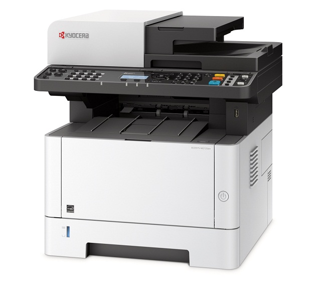
Kyocera ECOSYS M2135dn
Рейтинг


 Снят с производства
Тип устройства
МФУ
Технология печати
лазерная
Макс. формат
A4
Число страниц в месяц
20000
Скорость печати
A4
35
Цветность печати
черно-белая
Общие характеристики |
|
|---|---|
Телефон |
|
Макс. формат |
A4 |
Факс |
|
Печать фотографий |
|
Размещение |
настольный |
Число страниц в месяц |
20 000 |
Область применения |
малый офис |
Копир |
|
Сканер |
|
Тип |
лазерный/светодиодный |
Цветность печати |
|
Технология печати |
лазерная |
Тип устройства |
МФУ |
Принтер |
|
Пигментные чернила |
|
Система непрерывной подачи чернил |
|
Печать без полей |
|
Прямая печать |
|
Двусторонняя печать |
|
Время разогрева |
17 |
Макс, разрешение для ч/б печати |
|
| По Y | 1 200 |
| По X | 1 200 |
Скорость ч/б печати |
|
| A4 | 35 |
Время выхода первого отпечатка |
|
| Ч/б | 6,8 |
Копир |
|
Шаг масштабирования |
0,01 |
Время выхода первой копии |
6,9 |
Макс, количество копий за цикл |
999 |
Значение масштаба |
|
| Минимальное | 0,25 |
| Максимальное | 4 |
Макс, разрешение (ч/б) |
|
| По Y | 600 |
| По X | 600 |
Сканер |
|
Слайд-адаптер |
|
Макс. формат оригинала |
A4 |
Устройство автоподачи оригиналов |
одностороннее |
Тип сканера |
планшетный/протяжный |
Емкость устройства автоподачи оригиналов |
50 |
Оттенки серого |
256 |
Отправка изображения по e-mail |
|
Стандарт WIA |
|
Стандарт TWAIN |
|
Макс, размер сканирования |
|
| По Y | 297 |
| По X | 216 |
Разрешение сканера |
|
| По Х | 600 |
Расходные материалы |
|
Ресурс ч/б картриджа/тонера |
3 000 |
Количество картриджей |
1 |
Печать на: |
|
| Рулоне |
|
| Фотобумаге |
|
| CD/DVD |
|
| Конвертах |
|
| Карточках |
|
| Пленках |
|
| Этикетках |
|
| Матовой бумаге |
|
| Глянцевой бумаге |
|
Плотность бумаги |
|
| Максимальная | 220 |
| Минимальная | 60 |
Факс |
|
Цветной |
|
PC Fax |
|
Телефон |
|
Caller ID |
|
АОН |
|
Беспроводная трубка |
|
Проводная трубка |
|
Стандарт DECT |
|
Спикерфон |
|
Автоответчик |
|
Шрифты и языки управления |
|
Языки управления |
|
| PPDS |
|
| PostScript 2 |
|
| PCL 5c |
|
| PCL 6 |
|
|
|
|
| PostScript |
|
| PostScript 3 |
|
Количество установленных шрифтов |
|
| PostScript | 93 |
| PCL | 93 |
Лотки |
|
Емкость лотка ручной подачи |
100 |
Подача бумаги |
|
| Стандартная | 350 |
| Максимальная | 850 |
Вывод бумаги |
|
| Максимальный | 150 |
| Стандартный | 150 |
Финишер |
|
Сортер |
|
Брошюровщик |
|
Степлер |
|
Интерфейсы |
|
RS-232 |
|
LPT |
|
Инфракрасный порт |
|
Bluetooth |
|
Wi-Fi |
|
FireWire (IEEE 1394) |
|
AirPrint |
|
Устройство для чтения карт памяти |
|
Ethernet (RJ-45) |
|
USB |
|
Поддержка iOS |
|
Версия USB |
2,0 |
Количество свободных слотов расширения |
1 |
Поддержка карт памяти |
|
| Secure Digital |
|
Память/Процессор |
|
Макс, объем памяти |
1 536 |
Частота процессора |
800 |
Объем памяти |
512 |
Дополнительная информация |
|
Работа от аккумулятора |
|
Экран |
|
Поддержка ОС |
|
| DOS |
|
| Mac OS |
|
| Linux |
|
| Windows |
|
Потребляемая мощность |
|
| При работе | 661 |
| В режиме ожидания | 21 |
Уровень шума |
|
| При работе | 47,2 |
Габариты |
|
Глубина |
412 |
Высота |
437 |
Ширина |
417 |
Вес |
19 |
Модули
CASSETTE ASSEMBLY
DP Frame
DP Drive Section
Frame 2 (MFP)
PAPER FEED
PANEL
Image Formation Section 1
FRAME L
DP Unit
Fuser Section
Paper Conveying Section
PAPER CASSETTE
Operation Section 1
Operation Section 2
(Комплекты)
Covers (MFP)
ELECTRICAL COMPONENTS
SCANNER SECTION
PAPER FEED SECTION 2
DRIVE SECTION
DP Paper Feed Section
Front Covers (MFP)
Covers (PRINTER)
Operation Section 3
Frame 3 (PRINTER)
Image Formation Section 2
Frame 1
Labels
DP Covers
DP Conveying Section
Paper Feed Section 1
Front Covers (PRINTER)
Laser Scanner Section
Детали Covers (MFP)
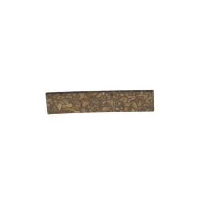
| Деталь: | Накладка площадки отделения бумаги из лотка ручной подачи |
| Парткод: | 302F908311 |
| Цена: | 90 ₽ |
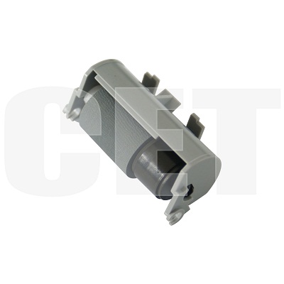
| Деталь: | Ролик отделения бумаги в держателе, в сборе |
| Парткод: | CET4322 |
| Цена: | 450 ₽ |
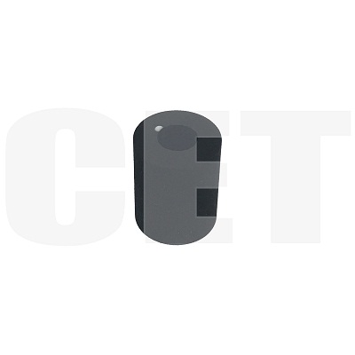
| Деталь: | Резина ролика отделения бумаги |
| Парткод: | CET4322PT |
| Цена: | 110 ₽ |

| Деталь: | Резина ролика захвата бумаги |
| Парткод: | CET7806BPT |
| Цена: | 110 ₽ |
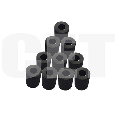
| Деталь: | Резина ролика подачи бумаги |
| Парткод: | CET7829 |
| Цена: | 150 ₽ |
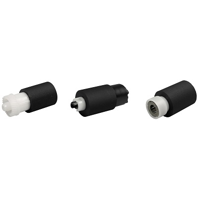
| Деталь: | Комплект роликов захвата / подачи / отделения бумаги |
| Парткод: | 302LK94140 |
| Цена: | 2 300 ₽ |

| Деталь: | HINGE LOW |
| Парткод: | 302S018610 |

| Деталь: | HINGE UP |
| Парткод: | 302S018620 |

| Деталь: | STOPPER ORIGINAL |
| Парткод: | 302S018250 |

| Деталь: | SPONGE ORIGINAL MAT |
| Парткод: | 303MX02060 |

| Деталь: | CUSHION ORIGINAL MAT B |
| Парткод: | 303MX02031 |

| Деталь: | BUSH SCREW |
| Парткод: | 3V2H702590 |

| Деталь: | PARTS SENSOR OPT. SP |
| Парткод: | 302P794010 |

| Деталь: | PARTS MOTOR-PM DP SP |
| Парткод: | 302S094010 |
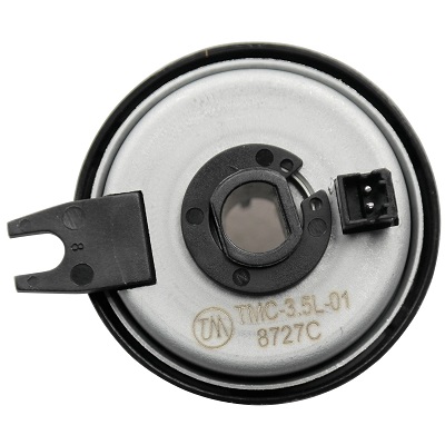
| Деталь: | PARTS CLUTCH 35 Z35R SP |
| Парткод: | 302NR94010 |

| Деталь: | 2RV94140 |
| Парткод: | 302RV94140 |

| Деталь: | 2RH94110 |
| Парткод: | 302RH94110 |

| Деталь: | 2RV94110 |
| Парткод: | 302RV94110 |

| Деталь: | 2RV94150 |
| Парткод: | 302RV94150 |

| Деталь: | SM055200 |
| Парткод: | 7SM010104+++H01 |

| Деталь: | 2M294130 |
| Парткод: | 302M294130 |

| Деталь: | 2NG94220 |
| Парткод: | 302NG94220 |

| Деталь: | 2S004130 |
| Парткод: | 302S004130 |

| Деталь: | 2S004140 |
| Парткод: | 302S004140 |

| Деталь: | 2ND94790 |
| Парткод: | 302ND94790 |

| Деталь: | 3PA94011 |
| Парткод: | 303PA94011 |

| Деталь: | 2R794340 |
| Парткод: | 302R794340 |

| Деталь: | 2R794330 |
| Парткод: | 302R794330 |

| Деталь: | Блок проявки |
| Парткод: | DV-1150 |
| Цена: | 11 800 ₽ |

| Деталь: | Узел переноса заряда в драм-картридже, в сборе |
| Парткод: | MC-1150 |
| Цена: | 3 900 ₽ |

| Деталь: | Блок лазера |
| Парткод: | LK-1150 |
| Цена: | 11 700 ₽ |

| Деталь: | MC-1150 |
| Парткод: | 302RV93080 |

| Деталь: | DK-1150 |
| Парткод: | 302RV93010 |
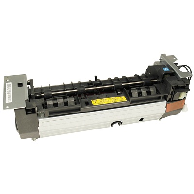
| Деталь: | PANEL UNIT, MFC9840CDW |
| Парткод: | FK-1150 |
| Цена: | 16 700 ₽ |

| Деталь: | Прижимной вал |
| Парткод: | PR-FK1150 |
| Цена: | 2 400 ₽ |

| Деталь: | Термоплёнка |
| Парткод: | FK-1150-FILM |
| Цена: | 2 500 ₽ |
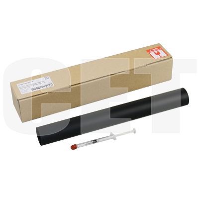
| Деталь: | Термоплёнка |
| Парткод: | CET7841 |
| Цена: | 2 800 ₽ |
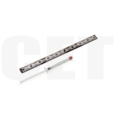
| Деталь: | Прижимная планка узла термозакрепления, в сборе |
| Парткод: | CET6901 |

| Деталь: | PARTS DP UNIT SP (U) |
| Парткод: | 302S093020 |

| Деталь: | PARTS DP UNIT SP (E) |
| Парткод: | 302S093010 |

| Деталь: | PARTS DP UNIT SP (U) |
| Парткод: | 302S393020 |

| Деталь: | PARTS DP UNIT SP (E) |
| Парткод: | 302S393010 |

| Деталь: | FK-1150 230V |
| Парткод: | 302RV93050 |

| Деталь: | FK-1152120V |
| Парткод: | 302RV93060 |

| Деталь: | FK-1151 100V |
| Парткод: | 302RY93020 |

| Деталь: | SPRING ACTUATOR REGIST |
| Парткод: | 302RV24330 |

| Деталь: | ACTUATOR REGIST |
| Парткод: | 302RV24080 |

| Деталь: | BUSH DU |
| Парткод: | 302RV24460 |

| Деталь: | PARTS ROLLER DU SP |
| Парткод: | 302RV94270 |

| Деталь: | BUSH 4 |
| Парткод: | 3V2K306460 |

| Деталь: | GEAR Z25L |
| Парткод: | 302RV29060 |

| Деталь: | GEAR Z23L |
| Парткод: | 302RV29070 |

| Деталь: | PARTS ROLLER TRANSFER A SP |
| Парткод: | 302LZ94070 |
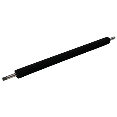
| Деталь: | PARTS ROLLER TRANSFER E SP |
| Парткод: | 302LZ94060 |
| Цена: | 4 300 ₽ |

| Деталь: | PARTS UNIT HIGH VOLTAGE SP |
| Парткод: | 302RV94190 |

| Деталь: | PARTS UNIT HIGH VOLTAGE J SP |
| Парткод: | 302RV94200 |

| Деталь: | PARTS ROLLER REGIST LOW SP |
| Парткод: | 302RV94250 |

| Деталь: | BUSH REGIST LOW L |
| Парткод: | 302RV24110 |

| Деталь: | BUSH REGIST LOW R |
| Парткод: | 302RV24120 |

| Деталь: | SPRING GUIDE REGIST |
| Парткод: | 302RV24340 |

| Деталь: | PARTS ROLLER REGIST UP SP |
| Парткод: | 302RV94240 |

| Деталь: | LABEL C |
| Парткод: | 302RV34020 |

| Деталь: | HOLDER DC BRUSH |
| Парткод: | 302RV24500 |

| Деталь: | BRUSH DISCHARGER |
| Парткод: | 302RV24190 |

| Деталь: | BRUSH DC DISCHARGER |
| Парткод: | 302RV24900 |
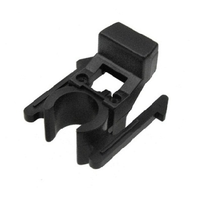
| Деталь: | BUSH TC R |
| Парткод: | 302HS24250 |
| Цена: | 200 ₽ |

| Деталь: | GEAR TRANS Z17L |
| Парткод: | 302RV24160 |

| Деталь: | LOCK BOTTOM |
| Парткод: | 302RV09150 |

| Деталь: | SPRING LOCK BOTTOM |
| Парткод: | 302RV09180 |

| Деталь: | CURSOR LEFT |
| Парткод: | 302RV09080 |

| Деталь: | CURSOR RIGHT |
| Парткод: | 302RV09090 |

| Деталь: | SPRING END /3070P319 A4 |
| Парткод: | 3V2BS06100 |

| Деталь: | GEAR CASSETTE |
| Парткод: | 5MVG127DN071 |

| Деталь: | CURSOR END |
| Парткод: | 302RV09100 |

| Деталь: | PAPER INDICATOR |
| Парткод: | 302RV09140 |

| Деталь: | SPRING BOTTOM |
| Парткод: | 302RV09050 |

| Деталь: | PLATE BOTTOM |
| Парткод: | 302RV09040 |

| Деталь: | PAD BOTTOM |
| Парткод: | 302F909210 |

| Деталь: | COVER CASSETTE |
| Парткод: | 302RV09030 |

| Деталь: | SPRING RETARD |
| Парткод: | 302RV09130 |

| Деталь: | HOLDER RETARD |
| Парткод: | 302RV09120 |
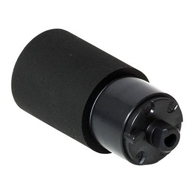
| Деталь: | RETARD ROLLER ASSY |
| Парткод: | 302F909171 |
| Цена: | 900 ₽ |

| Деталь: | GUIDE RETARD |
| Парткод: | 302RV09110 |

| Деталь: | CT-1150 |
| Парткод: | 302RV93090 |

| Деталь: | PARTS LCD COLOR S |
| Парткод: | 302K394171 |

| Деталь: | PARTS PWB PANEL MAIN ASSY SP |
| Парткод: | 302S594040 |

| Деталь: | PARTS PWB KEY RIGHT ASSY SP |
| Парткод: | 302R794220 |

| Деталь: | CONN.CORD ASSY FFC KEY RIGHT |
| Парткод: | 302S546050 |

| Деталь: | PARTS PWB KEY LEFT ASSY SP |
| Парткод: | 302R794250 |

| Деталь: | LABEL OPERATION T LEFT EN |
| Парткод: | 302S505710 |

| Деталь: | LABEL OPERATION T LEFT JP |
| Парткод: | 302S505720 |

| Деталь: | LABEL OPERATION T RIGHT EN |
| Парткод: | 302S505510 |

| Деталь: | LABEL OPERATION T RIGHT JP |
| Парткод: | 302S505520 |

| Деталь: | PARTS OPERATION ASSY SP |
| Парткод: | 302S594010 |

| Деталь: | PARTS PWB M PANEL ASSY SP |
| Парткод: | 302S094080 |

| Деталь: | LABEL OPERATION LCD 4 W EN |
| Парткод: | 302S205510 |

| Деталь: | LABEL OPERATION LCD 4 W JP |
| Парткод: | 302S205520 |

| Деталь: | LABEL OPERATION LCD EN |
| Парткод: | 302S005510 |

| Деталь: | LABEL OPERATION LCD 4 EN |
| Парткод: | 302S105510 |

| Деталь: | PARTS OPERATION ASSY SP |
| Парткод: | 302S294010 |

| Деталь: | PARTS OPERATION ASSY SP |
| Парткод: | 302S194010 |

| Деталь: | PARTS OPERATION ASSY SP |
| Парткод: | 302S094040 |

| Деталь: | Комплект для технического обслуживания |
| Парткод: | MK-1150 |
| Цена: | 14 900 ₽ |

| Деталь: | COVER LEFT |
| Парткод: | 302S004030 |

| Деталь: | COVER LEFT UP |
| Парткод: | 302S004070 |

| Деталь: | COVER ISU LEFT |
| Парткод: | 302S004100 |

| Деталь: | COVER ISU LEFT LGL |
| Парткод: | 302S004170 |

| Деталь: | COVER RIGHT |
| Парткод: | 302S004040 |

| Деталь: | COVER RIGHT UP |
| Парткод: | 302S004080 |

| Деталь: | COVER ISU RIGHT |
| Парткод: | 302S004110 |

| Деталь: | COVER ISU RIGHT LGL |
| Парткод: | 302S004180 |

| Деталь: | COVER REAR UP |
| Парткод: | 302S004090 |

| Деталь: | COVER REAR UP FAX |
| Парткод: | 302S404020 |

| Деталь: | COVER LEFT REAR |
| Парткод: | 302RV04080 |

| Деталь: | COVER REAR |
| Парткод: | 302RV28090 |

| Деталь: | COVER CASSETTE REAR |
| Парткод: | 302RV28110 |

| Деталь: | Cover Right Rear |
| Парткод: | 302S004210 |

| Деталь: | COVER DIMM |
| Парткод: | 302S004200 |

| Деталь: | PARTS UNIT LOW VOLTAGE 100V SP |
| Парткод: | 302S094090 |

| Деталь: | PARTS UNIT LOW VOLTAGE 230V SP |
| Парткод: | 302S094100 |
| Цена: | 12 200 ₽ |

| Деталь: | PARTS UNIT LOW VOLTAGE 100V SP |
| Парткод: | 302RV94210 |

| Деталь: | PARTS UNIT LOW VOLTAGE 230V SP |
| Парткод: | 302RV94220 |
| Цена: | 11 600 ₽ |

| Деталь: | PARTS PWB MAIN ENGINE ASSY SP |
| Парткод: | 302S094060 |

| Деталь: | PARTS PWB MAIN ENGINE ASSY EU SP |
| Парткод: | 302S094070 |

| Деталь: | PARTS PWB MAIN ENGINE ASSY SP |
| Парткод: | 302S194020 |

| Деталь: | PARTS PWB MAIN ENGINE ASSY EU SP |
| Парткод: | 302S194030 |

| Деталь: | PARTS PWB MAIN ENGINE ASSY SP |
| Парткод: | 302S294020 |

| Деталь: | PARTS PWB MAIN ENGINE ASSY SP |
| Парткод: | 302SG94010 |

| Деталь: | PARTS PWB MAIN ENGINE ASSY EU SP |
| Парткод: | 302SG94020 |

| Деталь: | PARTS PWB MAIN ENGINE ASSY SP |
| Парткод: | 302S394020 |

| Деталь: | PARTS PWB MAIN ENGINE ASSY EU SP |
| Парткод: | 302S394030 |

| Деталь: | PARTS PWB MAIN ENGINE ASSY EU SP |
| Парткод: | 302SH94010 |

| Деталь: | PARTS PWB MAIN ENGINE ASSY SP |
| Парткод: | 302S494010 |

| Деталь: | PARTS PWB MAIN ENGINE ASSY SP |
| Парткод: | 302S594020 |

| Деталь: | PARTS PWB MAIN ENGINE ASSY EU SP |
| Парткод: | 302S594030 |

| Деталь: | PARTS PWB MAIN ENGINE ASSY SP |
| Парткод: | 302RV94080 |

| Деталь: | PARTS PWB MAIN ENGINE ASSY EU SP |
| Парткод: | 302RV94090 |

| Деталь: | PARTS PWB MAIN ENGINE ASSY SP |
| Парткод: | 302RW94010 |

| Деталь: | PARTS PWB MAIN ENGINE ASSY EU SP |
| Парткод: | 302RW94020 |

| Деталь: | PARTS PWB MAIN ENGINE ASSY SP |
| Парткод: | 302RX94010 |

| Деталь: | PARTS PWB MAIN ENGINE ASSY EU SP |
| Парткод: | 302RX94020 |

| Деталь: | PARTS PWB MAIN ENGINE ASSY SP |
| Парткод: | 302RY94010 |

| Деталь: | PARTS PWB MAIN ENGINE ASSY EU SP |
| Парткод: | 302RY94020 |

| Деталь: | PARTS MOTOR ISU SP |
| Парткод: | 302R794380 |

| Деталь: | BELT ISU A |
| Парткод: | 302S017340 |

| Деталь: | BELT ISU |
| Парткод: | 302H917230 |
| Цена: | 1 000 ₽ |

| Деталь: | PARTS SENSOR A4 CIS SP |
| Парткод: | 302R794320 |

| Деталь: | PARTS SENSOR OPT SP |
| Парткод: | 302P794010 |

| Деталь: | CONN.CORD ASSY FFC ISU |
| Парткод: | 302S046020 |

| Деталь: | PARTS FRAME ISU TOP A ASSY SP |
| Парткод: | 302S094030 |

| Деталь: | PARTS FRAME ISU TOP L ASSY SP |
| Парткод: | 302S394010 |

| Деталь: | HOLDER SEPARATION MPF |
| Парткод: | 3V2LV08070 |

| Деталь: | PAD SEPARATION |
| Парткод: | 302R708310 |

| Деталь: | GUIDE TURN MPF |
| Парткод: | 302RV08020 |

| Деталь: | SPRING SEPARATION MPF |
| Парткод: | 302LV08110 |

| Деталь: | PLATE BOTTOM MPF |
| Парткод: | 302LV08080 |

| Деталь: | PAD FRICTION MPF |
| Парткод: | 302F908310 |

| Деталь: | PULLEY DU LOW |
| Парткод: | 302F929260 |

| Деталь: | PARTS ROLLER FD UP SP |
| Парткод: | 302RV94260 |

| Деталь: | GEAR Z21S |
| Парткод: | 302RV28130 |

| Деталь: | GEAR Z45S |
| Парткод: | 302M331100 |

| Деталь: | PARTS GEAR YUUSEI B ASSY SP |
| Парткод: | 302RV94060 |

| Деталь: | PARTS GEAR YUUSEI A ASSY SP |
| Парткод: | 302RV94050 |

| Деталь: | SOLENOID FD ASSY |
| Парткод: | 302HN44150 |

| Деталь: | PARTS MOTOR-BL W40 SP |
| Парткод: | 302LC94283 |

| Деталь: | GEAR Z61R-Z25R |
| Парткод: | 302RV31080 |

| Деталь: | GEAR Z69R-Z26L |
| Парткод: | 302RV31040 |

| Деталь: | PARTS CLUTCH 35 Z35R SP |
| Парткод: | 302NR94010 |

| Деталь: | PARTS PWB FRONT USB ASSY SP |
| Парткод: | 302RV94120 |

| Деталь: | SOLENOID MPF |
| Парткод: | 302HN44160 |

| Деталь: | PARTS PWB SWITCH ASSY SP |
| Парткод: | 302RV94130 |

| Деталь: | PARTS,FAN COOLING CONVEYING SP |
| Парткод: | 302FZ94420 |

| Деталь: | PARTS WIFI UNIT SP |
| Парткод: | 302R794010 |
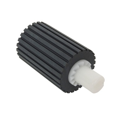
| Деталь: | PULLEY LEADING FEED ADF |
| Парткод: | 36211110 |
| Цена: | 750 ₽ |
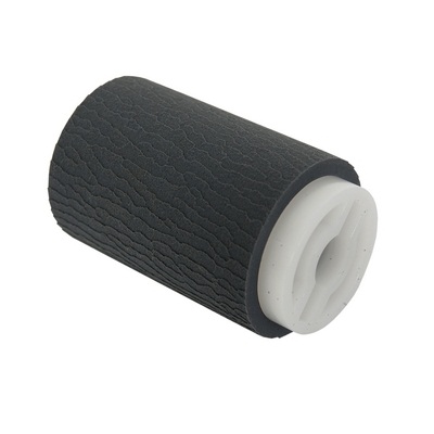
| Деталь: | PULLEY,PAPER FEED |
| Парткод: | 3BR07040 |
| Цена: | 420 ₽ |

| Деталь: | PARTS TABLE MAIN ASSY SP |
| Парткод: | 302S094020 |

| Деталь: | COVER TABLE |
| Парткод: | 302S018440 |

| Деталь: | LABEL DP TABLE |
| Парткод: | 302S334030 |

| Деталь: | LABEL DP TABLE |
| Парткод: | 302S034030 |

| Деталь: | PARTS HOLDER PAD ASSY SP |
| Парткод: | 302S094050 |

| Деталь: | COVER FRONT |
| Парткод: | 302S004050 |

| Деталь: | COVER FRONT |
| Парткод: | 302S404060 |

| Деталь: | LEVER CONTAINER |
| Парткод: | 302RV04160 |

| Деталь: | COVER FRONT UP |
| Парткод: | 302S004060 |

| Деталь: | KEY POWER |
| Парткод: | 302RV04150 |

| Деталь: | LABEL JAM OPERATION |
| Парткод: | 302RV34070 |

| Деталь: | LABEL CONTAINER OPERATION |
| Парткод: | 302RV34080 |

| Деталь: | STRAP COVER FRONT |
| Парткод: | 302RV04370 |

| Деталь: | LID TOP |
| Парткод: | 302S004020 |

| Деталь: | LID TOP |
| Парткод: | 302S404010 |

| Деталь: | COVER TOP |
| Парткод: | 302S004010 |

| Деталь: | STOPPER |
| Парткод: | 302RV04220 |

| Деталь: | RACK LID |
| Парткод: | 302S002030 |

| Деталь: | RACK FRONT |
| Парткод: | 302RV02420 |

| Деталь: | PARTS TRAY MPF ASSY SP |
| Парткод: | 302RV94010 |

| Деталь: | COVER LEFT |
| Парткод: | 302RV04030 |

| Деталь: | COVER RIGHT |
| Парткод: | 302RV04040 |

| Деталь: | COVER TOP REAR |
| Парткод: | 302RV04070 |

| Деталь: | COVER WIFI |
| Парткод: | 302RV04100 |

| Деталь: | COVER LEFT REAR |
| Парткод: | 302RV04080 |

| Деталь: | COVER REAR |
| Парткод: | 302RV28090 |

| Деталь: | COVER CASSETTE REAR |
| Парткод: | 302RV28110 |

| Деталь: | Cover Right Rear |
| Парткод: | 302RV04060 |

| Деталь: | COVER TOP |
| Парткод: | 302RX04010 |

| Деталь: | INDICATOR |
| Парткод: | 302RB05040 |

| Деталь: | KEY QUIET A |
| Парткод: | 302RB05030 |

| Деталь: | KEY QUIET B |
| Парткод: | 302RB05100 |

| Деталь: | KEY OPERATION |
| Парткод: | 302RB05020 |

| Деталь: | KEY OPERATION JP |
| Парткод: | 302RB05140 |

| Деталь: | PARTS PWB P PANEL ASSY SP |
| Парткод: | 302RX94030 |

| Деталь: | CONN.CORD ASSY FFC PANEL |
| Парткод: | 302RX46010 |

| Деталь: | PANEL LCD |
| Парткод: | 302RX05070 |

| Деталь: | PANEL LCD W |
| Парткод: | 302RY05010 |

| Деталь: | LABEL INDICATOR |
| Парткод: | 302RC34010 |

| Деталь: | LABEL INDICATOR W |
| Парткод: | 302RB34010 |

| Деталь: | LABEL QUIET MODE EN |
| Парткод: | 302RB34020 |

| Деталь: | LABEL QUIET MODE JP |
| Парткод: | 302RB34030 |

| Деталь: | COVER TOP |
| Парткод: | 302RV04010 |

| Деталь: | KEY GO-CANCEL |
| Парткод: | 302RV05010 |

| Деталь: | KEY QUIET-WIFI |
| Парткод: | 302RV05020 |

| Деталь: | PARTS PWB L PANEL ASSY SP |
| Парткод: | 302RV94100 |

| Деталь: | CONN.CORD ASSY FFC PANEL |
| Парткод: | 302RV46180 |

| Деталь: | COVER LED |
| Парткод: | 302RV05030 |

| Деталь: | COVER TOP |
| Парткод: | 302RW04010 |

| Деталь: | KEY WIFI |
| Парткод: | 302RV05090 |

| Деталь: | LABEL QUIET-WIFI |
| Парткод: | 302RW34010 |

| Деталь: | COVER LED |
| Парткод: | 302RW05020 |

| Деталь: | LID TOP |
| Парткод: | 302RV04020 |

| Деталь: | STOPPER |
| Парткод: | 302RV04220 |

| Деталь: | PARTS PWB ASSY FULL SENSOR SP |
| Парткод: | 302RV94140 |

| Деталь: | PARTS THERMOPILE ASSY SP |
| Парткод: | 302RH94110 |

| Деталь: | PARTS PWB ERASER ASSY SP |
| Парткод: | 302RV94110 |

| Деталь: | PARTS PWB THERMISTOR ASSY SP |
| Парткод: | 302RV94150 |

| Деталь: | SW. MICRO |
| Парткод: | 7SM010104+++H01 |

| Деталь: | PARTS PWB ASSY THERMISTOR SP |
| Парткод: | 302M294130 |

| Деталь: | PARTS FAN MOTOR SP |
| Парткод: | 302NG94220 |

| Деталь: | DV-1150 |
| Парткод: | 302RV93020 |

| Деталь: | DV-1152 |
| Парткод: | 302RV93030 |

| Деталь: | DV-1151 |
| Парткод: | 302RY93010 |

| Деталь: | DV-1154 |
| Парткод: | 302RV93040 |

| Деталь: | PARTS DC MOTOR ASSY SP |
| Парткод: | 302RV94180 |
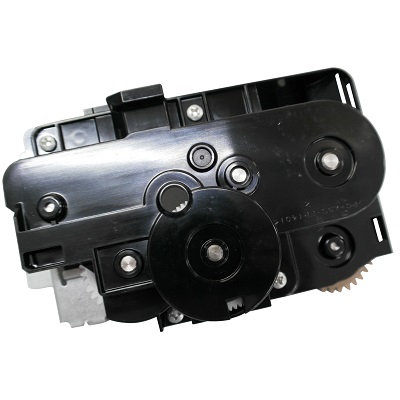
| Деталь: | PARTS PLATE DRIVE FUSER ASSY SP |
| Парткод: | 302RV94020 |
| Цена: | 850 ₽ |

| Деталь: | PARTS DRIVE PRESS RELEASE ASSY SP |
| Парткод: | 302RV94030 |

| Деталь: | EMBLEM |
| Парткод: | 302S018490 |

| Деталь: | EMBLEM MACHINE NUMBER |
| Парткод: | 302RV34010 |

| Деталь: | EMBLEM MACHINE NUMBER |
| Парткод: | 302RW34020 |

| Деталь: | EMBLEM MACHINE NUMBER |
| Парткод: | 302RX34010 |

| Деталь: | EMBLEM MACHINE NUMBER |
| Парткод: | 302RY34010 |

| Деталь: | EMBLEM MACHINE NUMBER |
| Парткод: | 302S034010 |

| Деталь: | EMBLEM MACHINE NUMBER |
| Парткод: | 302S134010 |

| Деталь: | EMBLEM MACHINE NUMBER |
| Парткод: | 302S234010 |

| Деталь: | EMBLEM MACHINE NUMBER |
| Парткод: | 302SG34010 |

| Деталь: | EMBLEM MACHINE NUMBER |
| Парткод: | 302S334010 |

| Деталь: | EMBLEM MACHINE NUMBER |
| Парткод: | 302SH34010 |

| Деталь: | EMBLEM MACHINE NUMBER |
| Парткод: | 302S434010 |

| Деталь: | EMBLEM MACHINE NUMBER |
| Парткод: | 302S534010 |

| Деталь: | COVER REAR |
| Парткод: | 302S018060 |

| Деталь: | COVER FRONT |
| Парткод: | 302S018050 |

| Деталь: | COVER DP FEED |
| Парткод: | 302S018040 |

| Деталь: | PARTS PLATE ORIGINAL SP |
| Парткод: | 303LJ94070 |

| Деталь: | PARTS PLATE ORIGINAL SP |
| Парткод: | 302R794130 |

| Деталь: | ACTUATOR BASE |
| Парткод: | 302S018560 |

| Деталь: | GUIDE READING |
| Парткод: | 302S018120 |

| Деталь: | ACTUATOR TIMING C |
| Парткод: | 302S018260 |

| Деталь: | GEAR Z30R |
| Парткод: | 302S018370 |

| Деталь: | GEAR Z25L |
| Парткод: | 302S018170 |

| Деталь: | ACTUATOR TIMING A |
| Парткод: | 302S018150 |

| Деталь: | PARTS SENSOR OPT SP |
| Парткод: | 302P794010 |

| Деталь: | GUIDE READING |
| Парткод: | 302S018120 |

| Деталь: | ACTUATOR SET |
| Парткод: | 302S018180 |

| Деталь: | COVER PI |
| Парткод: | 302S018690 |

| Деталь: | PARTS SENSOR A4 CIS SP |
| Парткод: | 302R794320 |

| Деталь: | ACTUATOR TIMING B |
| Парткод: | 302S318030 |

| Деталь: | GEAR Z25L |
| Парткод: | 303LL31430 |

| Деталь: | GEAR Z22S FEED |
| Парткод: | 302HS06090 |
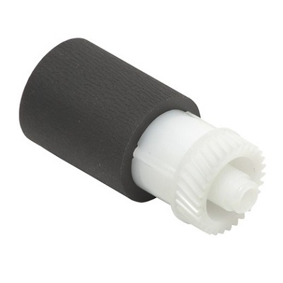
| Деталь: | PULLEY PICKUP ASSY |
| Парткод: | 302HN06080 |
| Цена: | 480 ₽ |
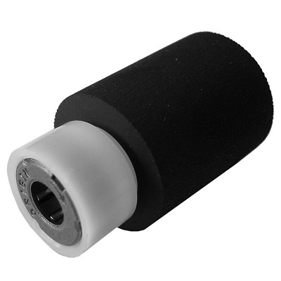
| Деталь: | PULLEY FEED ASSY |
| Парткод: | 302F906230 |
| Цена: | 750 ₽ |

| Деталь: | PULLEY EXIT /A-49 FUSER A3 |
| Парткод: | 5MVM273DB005 |

| Деталь: | PARTS ROLLER MIDDLE SP |
| Парткод: | 302RV94230 |

| Деталь: | SHAFT FEED R |
| Парткод: | 302RV06040 |

| Деталь: | PARTS SENSOR OPT. SP |
| Парткод: | 302P794010 |

| Деталь: | ACTUATOR EMPTY B |
| Парткод: | 302HS06071 |

| Деталь: | ACTUATOR EMPTY A |
| Парткод: | 302RV06080 |

| Деталь: | GEAR Z14S |
| Парткод: | 302RV08060 |

| Деталь: | FRAME MPF |
| Парткод: | 302RV08010 |

| Деталь: | LOCK DLP |
| Парткод: | 302F908340 |

| Деталь: | PARTS PWB CONTAINER CONNECT ASSY SP |
| Парткод: | 302RV94160 |

| Деталь: | PARTS PWB ASSY EMPTY SENSOR SP |
| Парткод: | 302RV94170 |

| Деталь: | ACTUATOR MPF |
| Парткод: | 302LV08180 |
| Цена: | 180 ₽ |

| Деталь: | SPRING ACTUATOR MPF |
| Парткод: | 302LV08201 |
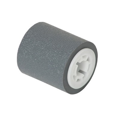
| Деталь: | ROLLER M/P ASSY |
| Парткод: | 302HS08260 |
| Цена: | 700 ₽ |

| Деталь: | SHAFT FEED MPF |
| Парткод: | 302RV08070 |

| Деталь: | PARTS HOLDER FEED ASSY SP |
| Парткод: | 302RV94070 |
| Цена: | 3 100 ₽ |

| Деталь: | COVER FRONT |
| Парткод: | 302RV04050 |

| Деталь: | COVER FRONT |
| Парткод: | 302RV04020 |

| Деталь: | LEVER CONTAINER |
| Парткод: | 302RV04160 |

| Деталь: | COVER FRONT UP |
| Парткод: | 302RV04130 |

| Деталь: | KEY POWER |
| Парткод: | 302RV04150 |

| Деталь: | LABEL JAM OPERATION |
| Парткод: | 302RV34070 |

| Деталь: | LABEL CONTAINER OPERATION |
| Парткод: | 302RV34080 |

| Деталь: | STRAP COVER FRONT |
| Парткод: | 302RV04370 |

| Деталь: | PARTS TRAY MPF ASSY SP |
| Парткод: | 302RV94010 |

| Деталь: | LK-1150 |
| Парткод: | 302RV93070 |

| Деталь: | CONN.CORD ASSY FFC APC |
| Парткод: | 302RV46160 |
Коды ошибок
0030
0070
0100
0120
0130
0140
0150
0160
0170
0180
0190
0500
0510
0530
0540
0800
0830
0840
0870
0920
0970
1810
1820
2000
2010
2600
2610
3100
3200
3210
3300
3310
3500
4000
4010
4201
6000
6020
6030
6050
6200
6220
6230
6250
6400
6600
6610
6650
7220
7800
7990
F000
F010
F020
F040
F041
F050
F051
F12X
F14X
F15X
F18X
F1DX
F21X, F22X, F23X
F24X
F25X
F26X ... F2AX
F2BX ... F32X
F33X
F34X
F35X
F37X
F38X
F3AX ... F45X
F46X
F47X, F48X, F49X
F4DX, F4EX
F4FX
F50X
F51X ... F57X
F58X ... F5EX
F5FX
F62X
F63X
F69X ... F6CX
Описание
| Error code: | 0030 |
| Description: | FAX control PWB system error Processing with the fax software was disabled due to a software problem. |
| Causes: | Defective FAX control PWB. |
| Remedy: | FAX control PWB 1. Turn the main power swtch off and after 5 seconds, re-mount the FAX controller PWB, then turn power on. 2. Reinstall the fax software. 3. Replace the FAX control PWB. |
| Error code: | 0070 |
| Description: | FAX control PWB incompatible detection error Abnormal detection of FAX control PWB incompatibility In the initial communication with the FAX control PWB, any normal communication command is not transmitted. |
| Causes: | Defective FAX software. Defective FAX control PWB. |
| Remedy: | FAX control PWB (The FAX PWB installed will not be the one designed for the machine.) 1. Install the FAX system designed for the model. 2. Reinstall the fax software. |
| Error code: | 0100 |
| Display: | MAINTENANCE CALL 0100 |
| Description: | Backup memory device error |
| Causes: | Defective flash memory. Defective main PWB. |
| Remedy: | EEPROM (main PWB) 1. Turn the main power swtch off and after 5 seconds, then turn power on. 2. Check that the EEPROM on the main circuit PWB is peroperly installed on the main circuit PWB and, if not, re-install it. 3. Replace the main PWB |
| Error code: | 0120 |
| Description: | There is a problem with Thermistor for Pre-Heater. |
| Causes: | Thermistor Cable has short circuited or cutline. Thermistor has a problem. |
| Remedy: | Check Cable connection around Thermistor Thermistor replacement |
| Error code: | 0130 |
| Description: | There is a problem with Thermistor for Print Heater. |
| Causes: | Thermistor cable has short circuited or cutline. Thermistor has a problem. |
| Remedy: | Check Cable connection around Thermistor Thermistor replacement |
| Error code: | 0140 |
| Description: | There is a problem with Thermistor for dryer. |
| Causes: | Thermistor cable has short circuited or cutline. Thermistor has a problem. |
| Remedy: | Check Cable connection around Thermistor Thermistor replacement |
| Error code: | 0150 |
| Description: | Even though the machine carries out the regular movement, the output of Slider Sensor does not reach the expected value. |
| Causes: | Slider Motor has a problem. Slider Sensor has a problem. Wiring or Flexible Cable has short circuitted or cut-line. Servo Board has a problem. |
| Remedy: | Check Cable connection of Servo Board Check Cable connection of Junction Board Slider Motor replacement Slider Sensor replacement Wiring or Flexible Cable replacement Servo Board replacement |
| Error code: | 0160 |
| Description: | Even though the machine carries out the regular movement, the output of Pressure Pump 1 Sensor does not reach the expected value. |
| Causes: | Pressure Pump 1 Motor has a problem. Pressure Pump 1 Sensor has a problem. Pressure Pump 1 Magnet has dropped out. Wiring or Flexible Cable has short circuitted or cut-line. Pump Drive Board has a problem. Servo Board has a problem. |
| Remedy: | Check Cable connection of Servo Board Check Cable connection of Junction Board Check Pressure Pump 1 Magnet Pressure Pump 1 Motor replacement Pressure Pump 1 Sensor replacement Wiring or Flexible Cable replacement Pump Drive Board replacement Servo Board replacement |
| Error code: | 0170 |
| Description: | Even though the machine carries out the regular movement, the output of Supply Pump 1 Sensor does not reach the expected value. |
| Causes: | Supply Pump 1 Motor has a problem. Supply Pump 1 Sensor has a problem. Supply Pump 1 Magnet has dropped out. Wiring or Flexible Cable has short circuitted or cut-line. Pump Drive Board has a problem. Servo Board has a problem. |
| Remedy: | Check Cable connection of Servo Board Check Cable connection of Junction Board Check Supply Pump 1 Magnet Supply Pump 1 Motor replacement Supply Pump 1 Sensor replacement Wiring or Flexible Cable replacement Pump Drive Board replacement Servo Board replacement |
| Error code: | 0180 |
| Description: | Even though the machine carries out the regular movement, the output of Maintenance Liquid Pump Sensor does not reach the expected value. |
| Causes: | Maintenance Liquid Pump Motor has a problem. Maintenance Liquid Pump Sensor has a problem. Maintenance Liquid Pump Magnet has dropped out. Wiring or Flexible Cable has short circuitted |
| Remedy: | Check Cable connection of Servo Board Check Cable connection of Junction Board Maintenance Liquid Pump Motor replacement Maintenance Liquid Pump Sensor replacement Wiring or Flexible Cable replacement Servo Board replacement |
| Error code: | 0190 |
| Description: | Thermistor under the BED has a problem. |
| Causes: | Device has a problem. Thermistor Cable has short circuited or cutline. |
| Remedy: | Thermistor replacement Check Cable connection Heater Board replacement |
| Error code: | 0500 |
| Display: | FUSER ERROR |
| Description: | Fuser warm-up failure |
| Causes: | • The thermistor /1 does not detect the specified temperature and the warm-up cycle is not completed even after the lapse of a given period of time after the cycle has been started. |
| Remedy: | 1 Change fuser unit. - - 2 For C110: 1. Main switch is turned ON. 2. Open the top cover. 3. Press the following keys in this order. ROTATE TONER key -ATTENTION key - ATTENTION key - ROTATE TONER key. 4. Main switch is turned OFF/ON. For C130n: 1. Main switch is turned ON. 2. Execute [SERVICE MENU] - [FUSER UNLOCK]. See P.103 - - 3 Change PRCB. - - 4 Change DCPU. - - |
| Error code: | 0510 |
| Display: | Fuser failure CODE (0510) Turn power off, on |
| Description: | 0502 Thermistor Failure, 0510 Fuser Failure, and 0520 Fuser Failure 0510 Fuser Failure The temperature detected by the thermistor remains lower than expected for a given period of time or longer. |
| Causes: | • Fuser, PL4.0.13 • Engine Control Board, PL13.0.20 • Power Supply, PL13.0.17 |
| Remedy: | 1 Check that the Fuser is installed correctly. Does the problem persist? Go to step 2. Complete. 2 Check the Engine Control Board connectors P/J2, P/J3, and P/J6. Are the connectors seated properly? Go to step 3 Reseat the connectors. If the problem persists, go to step 3. 3 Check the Low Voltage Power Supply connectors CN3, CN5, and CN7. Are the connectors seated properly? Go to step 4. Reseat the connectors. If the problem persists, go to step 4. 4 Replace the Fuser (8-9). Does the problem persist? Go to step 5. Complete. 5 Replace the Engine Control Board. Does the problem persist? Go to step 6. Complete. 6 Replace the Power Supply. Complete. |
| Error code: | 0530 |
| Description: | Backup task error detection The time for the backup task not being in operation is 30s or more |
| Remedy: | Main/Engine PWB Turn the power switch off and on If not corrected, replace the main/ engine PWB. |
| Error code: | 0540 |
| Description: | Unexpected engine firmware control detection? (Preventing the solenoid from continuously being on) The solenoid was continuously on for the specified time or more |
| Remedy: | Main/Engine PWB Turn the power switch off and on If not corrected, replace the main/ engine PWB. |
| Error code: | 0800 |
| Display: | Print Unable 08 Turn the power off and then back on again. |
| Description: | Image processing error JAM010X is detected twice. |
| Causes: | Defective main PWB. |
| Remedy: | Main PWB Replace the main PWB. |
| Error code: | 0830 |
| Description: | FAX control PWB flash program area checksum error A checksum error occurred with the program of the FAX control PWB |
| Causes: | Defective FAX software. Defective FAX control PWB. |
| Remedy: | FAX software 1. Reinstall the fax software. FAX control PWB 1. Execute initializing by U600.(Refer to the FAX service manual) 2. Replace the FAX control PWB. |
| Error code: | 0840 |
| Description: | Faults of RTC (“Time for maintenance T” is displayed) [Check at power up] The RTC setting has reverted to a previous state. The machine has not been powered for 5 years (compared to the settings stored periodically in the EEPROM). The RTC setting is older than 00:01 on January 1, 2000. [Checked periodically (in 5- minute interval) after powered up] The RTC setting has reverted to a state older than the last time it was checked. 10 minutes have been passed since the previous check. After C840 is detected, the machine enters in disconnection mode after the main power switch has been switched on and off and indicates ‘Maintenance T.’ |
| Causes: | The battery is disconnected from the main PWB Defective main PWB. |
| Remedy: | Battery (main PWB) 1. Make sure that the back-up batteries on the main PWB are not short-circuited. 2. Reset Maintenance T by executing U906. 3. If the same C call is displayed when power is switched on and off, replace the back up battery. 4. If communication error (due to a noise, etc.) is present with the RTC on the main circuit PWB, check the PWB is properly grounded. Main PWB Replace the main PWB |
| Error code: | 0870 |
| Description: | PCFAX control PWB to main PWB high capacity data transfer error High-capacity data transfer between the FAX control PWB and the main PWB of the machine was not normally performed even if the data transfer was retried the specified times. |
| Causes: | Improper installation FAX control PWB. Defective FAX control PWB or main PWB. |
| Remedy: | FAX control PWB 1. Turn the main power swtch off and after 5 seconds, re-mount the FAX controller PWB, then turn power on. 2. Replace the FAX control PWB. HDD Execute U024 to initialize the HDD. Main PWB Replace the main PWB. |
| Error code: | 0920 |
| Description: | Fax file system error The backup data is not retained for file system abnormality of flash memory of the FAX control PWB. |
| Causes: | Defective FAX control PWB. |
| Remedy: | FAX control PWB 1. Execute initializing by U600 (Refer to the FAX service manual). 2. Replace the FAX control PWB. |
| Error code: | 0970 |
| Description: | 12 V power down detect Power is disconnected during sleeping. |
| Causes: | Defective power source PWB. |
| Remedy: | Replace the power source PWB and check for correct operation. |
| Error code: | 1810 |
| Description: | Side multi tray communication error A communication error from side multi tray is detected 10 times in succession. |
| Causes: | Improper installation side multi tray. Defective connector cable or poor contact in the connector. Defective engine PWB. Defective SM main PWB. |
| Remedy: | Side multi tray Check the wiring connection status with the main unit and, if necessary, try connecting it again. SM main PWB 1. Confirm that the wiring connector is firmly connected and, if necessary, connect the connector all the way in. SM main PWB (YC1) and Engine PWB (YC19) 2. If the wiring is disconnected, shorted or grounded, replace the wiring. 3. Replace the SM main PWB (Refer to the service manual for the paper feeder). Engine PWB Check the engine software and upgrade to the latest, if necessary. Replace the engine PWB. SM main PWB Replace the SM main PWB (Refer to the service manual for the paper feeder). |
| Error code: | 1820 |
| Description: | Side paper feeder communication error A communication error from paper feeder is detected 10 times in succession. |
| Causes: | Improper installation side paper feeder. Defective connector cable or poor contact in the connector. Defective engine PWB. Defective SM main PWB. Defective PF main PWB. |
| Remedy: | Side paper feeder Check the wiring connection status with the main unit and, if necessary, try connecting it again. SM main PWB 1. Confirm that the wiring connector is firmly connected and, if necessary, connect the connector all the way in. SM main PWB (YC1) and Engine PWB (YC19) 2. If the wiring is disconnected, shorted or grounded, replace the wiring. 3. Replace the SM main PWB (Refer to the service manual for the paper feeder). PF main PWB 1. Confirm that the wiring connector is firmly connected and, if necessary, connect the connector all the way in. PF main PWB (YC13) and SM main PWB (YC4) 2. If the wiring is disconnected, shorted or grounded, replace the wiring. 3. Replace the PF main PWB (Refer to the service manual for the paper feeder). Engine PWB 1. Check the engine software and upgrade to the latest, if necessary. 2. Replace the engine PWB. |
| Error code: | 2000 |
| Description: | DDA Communication Error. |
| Causes: | The communication error occurs when the IC4 or IC22 on the Main Board is broken. And it causes the Motor Error. |
| Remedy: | Replace the Main Board. |
| Error code: | 2010 |
| Display: | Paper loaded askew. Press Load/Eject and reload the paper. |
| Description: | Main motor startup error Main motor is not stabilized within 1 s since the motor is activated. |
| Causes: | Main motor. Engine PWB |
| Remedy: | Main motor 1. To check the motor operation execute U030 Main (main motor). 2. Confirm that the wiring connector is firmly connected and, if necessary, connect the connector all the way in. Main motor and Engine PWB (YC13) 3. If the wiring is disconnected, shorted or grounded, replace the wiring. 4. Replace the main motor. Engine PWB 1. Check the engine software and upgrade to the latest, if necessary. 2. Replace the engine PWB. |
| Error code: | 2600 |
| Description: | PF paper feed motor error (large capacity feeder) After PF paper feed motor is driven, the ready signal does not turn to L within 2 s. |
| Causes: | Defective connector cable or poor contact in the connector. Defective drive transmission system of motor. Defective PF paper feed motor. Defective PF main PWB. |
| Remedy: | PF paper feed motor 1. To check the feed unit operation, execute U247 LCF- Motor ON. 2. Check the paper feed roller and drive gear can rotate or they are not unusually loaded and, if necessary, replace. 3. Confirm that the wiring connector is firmly connected and, if necessary, connect the connector all the way in. PF paper feed motor and PF main PWB (YC16) 4. If the wiring is disconnected, shorted or grounded, replace the wiring. 5. Replace the paper feed motor. PF main PWB Replace the PF main PWB (Refer to the service manual for the paper feeder). |
| Error code: | 2610 |
| Description: | PF paper feed motor error (paper feeder) After PF paper feed motor is driven, the ready signal does not turn to L within 2 s. |
| Causes: | Defective connector cable or poor contact in the connector. Defective drive transmission system of motor. Defective PF paper feed motor. Defective PF main PWB. |
| Remedy: | PF paper feed motor 1. To check the feed unit operation, execute U247 2PF - Motor ON. 2. Check the paper feed roller and drive gear can rotate or they are not unusually loaded and, if necessary, replace. 3. Confirm that the wiring connector is firmly connected and, if necessary, connect the connector all the way in. PF paper feed motor and PF main PWB (YC16) 4. If the wiring is disconnected, shorted or grounded, replace the wiring. 5. Replace the paper feed motor. PF main PWB Replace the PF main PWB (Refer to the service manual for the paper feeder). |
| Error code: | 3100 |
| Description: | Scanner carriage error The home position is not correct when the power is turned on, at the end of a reading process of the table and document processor. |
| Causes: | Defective connector cable or poor contact in the connector. Defective home position sensor. Defective scanner motor. Defective ISC PWB. Defective main PWB. |
| Remedy: | The scanner mirror frame is being locked after setup. Check whether the scanner mirror frame has been unlocked and unlock if necessary. Scanner motor 1. To check the scanner motor, execute U073. 2. Move the scanner by the hand to check whether it is unusually difficult to move. 3. Check that the optical wire rope is not disengaged and engage the wire. 4. Confirm that the wiring connector is firmly connected and, if necessary, connect the connector all the way in. Scanner motor and ISC PWB (YC5) ISC PWB (YC3) and Main PWB (YC11) 5. If the wiring is disconnected, shorted or grounded, replace the wiring. 6. Replace the scanner motor. Home position sensor 1. Check that the sensor is correctly positioned. 2. Confirm that the wiring connector is firmly connected and, if necessary, connect the connector all the way in. Home position sensor and ISC PWB (YC8) 3. Replace the home position sensor. ISC PWB Replace the ISC PWB and execute U411. Main PWB Replace the main PWB. |
| Error code: | 3200 |
| Description: | Exposure lamp error When input value at the time of LED lamp PWB illumination does not exceed the threshold value between 5 s. |
| Causes: | Defective connector cable or poor contact in the connector. Defective LED lamp PWB. Defective ISC PWB. Defective main PWB. |
| Remedy: | Defective connector cable or poor contact in the connector. Reinsert the connector. Also check for continuity within the connector cable. If none, replace the cable. LED lamp PWB and ISC PWB (YC6) CCD PWB (YC2) and ISC PWB (YC9) ISC PWB (YC3) and main PWB (YC11) Defective LED lamp PWB. Replace the LED lamp PWB and check for correct operation. Defective ISC PWB. Replace the ISC PWB and check for correct operation. Defective CCD PWB. Replace the ISU and check for correct operation. Defective main PWB. Replace the main PWB and check for correct operation. |
| Error code: | 3210 |
| Description: | CIS lamp error When input value at the time of CIS illumination does not exceed the threshold value between 5 s. |
| Causes: | Defective connector cable or poor contact in the connector. Defective CIS. Defective DPSHD PWB. Defective DP relay PWB. |
| Remedy: | CIS 1. Execute U906 Separating Operation Release. 2. Execute CCD of U061 lamp check. 3. Confirm that the wiring connector is firmly connected and, if necessary, connect the connector all the way in. CIS and DPSHD PWB (YC2) DPSHD PWB (YC3) and DP relay PWB (YC2) 4. If the wiring is disconnected, shorted or grounded, replace the wiring. 5. Replace the CIS and execute U091 and U411. DPSHD PWB Replace the DPSHD PWB. DP relay PWB Replace the DP relay PWB. |
| Error code: | 3300 |
| Description: | Optical system (AGC) error One of the gains is FF or 00 during the CCD lamp AGC is being processed. |
| Causes: | Defective connector cable or poor contact in the connector. Defective exposure lamp Defective CCD PWB. Defective ISC PWB. Defective main PWB. |
| Remedy: | LED lamp PWB 1. To check the lamp, execute U061 CCD. 2. Confirm that the wiring connector is firmly connected and, if necessary, connect the connector all the way in. LED lamp PWB and ISC PWB (YC6) CCD PWB (YC2) and ISC PWB (YC9) ISC PWB (YC3) and Main PWB (YC11) 3. If the wiring is disconnected, shorted or grounded, replace the wiring. 4. If the LED lamp won’t light, replace the LED PWB and execut U411. CCD PWB Replace the ISU and execute U411. ISC PWB Replace the ISC PWB and execute U411. Main PWB Replace the main PWB. |
| Error code: | 3310 |
| Description: | CIS AGC error After AGC, correct input is not obtained at CIS. |
| Causes: | Defective CIS. Defective DPSHD PWB. Defective DP relay PWB. |
| Remedy: | CIS 1. Execute U906 Separating Operation Release. 2. To check the lamp, execute U061 CCD. 3. Confirm that the wiring connector is firmly connected and, if necessary, connect the connector all the way in. DP CIS and DPSHD PWB (YC2) DPSHD PWB (YC3) and DP relay PWB (YC2) 4. If the wiring is disconnected, shorted or grounded, replace the wiring. 5. Replace the CIS and execute U091 and U411. DPSHD PWB Replace the DPSHD PWB. |
| Error code: | 3500 |
| Description: | Communication error between scanner and ASIC An error code is detected. |
| Causes: | Defective connector cable or poor contact in the connector. Defective ISC PWB. Defective main PWB. |
| Remedy: | ISC PWB 1. Confirm that the wiring connector is firmly connected and, if necessary, connect the connector all the way in. ISC PWB (YC3) and Main PWB (YC11) 2. If the wiring is disconnected, shorted or grounded, replace the wiring. 3. Replace the ISC PWB and execute U411. Main PWB Replace the main PWB. |
| Error code: | 4000 |
| Display: | Supplies Drum End Soon. |
| Description: | Command Communication Error. |
| Causes: | The communication error occurs when the IC4 or IC22 on the Main Board is broken. And it causes the Motor Error. |
| Remedy: | Replace the Main Board. |
| Error code: | 4010 |
| Description: | Polygon motor steady-state error Stable OFF is detected for 1 s continuously after polygon motor stabilized. |
| Causes: | Defective connector cable or poor contact in the connector. Defective polygon motor. Defective engine PWB. |
| Remedy: | Defective connector cable or poor contact in the connector. Reinsert the connector. Also check for continuity within the connector cable. If none, replace the cable. Laser scanner unit and engine PWB (YC11) Defective polygon motor. Replace the laser scanner unit. Defective engine PWB. Replace the engine PWB and check for correct operation. |
| Error code: | 4201 |
| Display: | Replace Drum:BK |
| Description: | BD steady-state error K The BD signal is not detected. |
| Causes: | Defective connector cable or poor contact in the connector. Defective PD PWB. Defective engine PWB. |
| Remedy: | PD PWB K (LSU) 1. Confirm that the FFC wiring connector is not distorted and connect the FFC wiring all the way in. Laser scanner unit and LSU relay PWB (YC3) LSU relay PWB (YC2) and Engine PWB (YC11) 2. If the FFC wiring is disconnected, shorted or grounded, replace the FFC wiring. 3. Replace the laser scanner unit. Engine PWB 1. Check the engine software and upgrade to the latest, if necessary. 2. Replace the engine PWB. |
| Error code: | 6000 |
| Description: | Broken fuser heater wire Fuser thermistor 1 does not reach 100° C/212 °F even after 30 s during warming up. The detected temperature of fuser thermistor 1 does not reach the specified temperature (ready indication temperature) for 420 s in warming up after reached to 100° C/212 °F. |
| Causes: | Defective connector cable or poor contact in the connector. Deformed connector pin. Defective triac. Fuser thermostat triggered. Defective fuser heater. Defective engine PWB. |
| Remedy: | Fuser unit 1. Check that no paper jam is present. 2. Confirm that the wiring connector is firmly connected and, if necessary, connect the connector all the way in. Fuser unit and Engine PWB (YC26) 3. If the wiring is disconnected, shorted or grounded, replace the wiring. 4. Replace the Fuser unit Replace the Fuser unit. (Deteriorated sensitivity due to the toner adhered to the center thermistor.) Engine PWB 1. Check the engine software and upgrade to the latest, if necessary. 2. Replace the engine PWB. Power source PWB 1. Confirm that the wiring connector is firmly connected and, if necessary, connect the connector all the way in. Power source PWB (YC3) and fuser heater PWB (YC3) Fuser heater PWB (YC2) and feed PWB 1 (YC27) Feed PWB 1 (YC1) and Engine PWB (YC6) Fuser heater 1. Replace the fuser unit. |
| Error code: | 6020 |
| Description: | Abnormally high fuser thermistor 1 temperature Fuser thermistor 1 detects a temperature higher than 240°C/464°F for 1 s. |
| Causes: | Deformed connector pin. Defective triac. Shorted fuser thermistor 1. Defective engine PWB. |
| Remedy: | Fuser unit 1. Confirm that the wiring connector is firmly connected and, if necessary, connect the connector all the way in. Fuser unit and Engine PWB (YC26) 2. If the wiring is disconnected, shorted or grounded, replace the wiring. 3. Replace the Fuser unit. Engine PWB 1. Check the engine software and upgrade to the latest, if necessary. 2. Replace the engine PWB. |
| Error code: | 6030 |
| Description: | Broken fuser thermistor 1 wire Input from fuser center thermistor 1 is 1010 or more (A/D value) continuously for 1 s. Verify if A/D read in the differential output won’t change by 4 or more when it was turned on for 10 seconds in a lowtemperature environment. |
| Causes: | Defective connector cable or poor contact in the connector. Deformed connector pin. Defective triac. Broken fuser thermistor 1 wire. Fuser thermostat triggered. Defective fuser heater. Defective engine PWB. |
| Remedy: | Fuser unit 1. Check that no paper jam is present. 2. Confirm that the wiring connector is firmly connected and, if necessary, connect the connector all the way in. Fuser unit and Engine PWB (YC26) 3. If the wiring is disconnected, shorted or grounded, replace the wiring. 4. Replace the Fuser unit. (Deteriorated sensitivity due to the toner adhered to the center thermistor.) Engine PWB 1. Check the engine software and upgrade to the latest, if necessary. 2. Replace the engine PWB. Fuser thermistor 1 1. Replace the Fuser unit. Fuser thermostat (triggered) 1. Confirm that the wiring connector is firmly connected and, if necessary, connect the connector all the way in. Fuser unit and fuser heater PWB (YC1) 2. If the wiring is disconnected, shorted or grounded, replace the wiring. 3. Replace the Fuser unit. |
| Error code: | 6050 |
| Description: | Abnormally low fuser thermistor 1 temperature Fuser thermistor 1 detects a temperature lower than 100°C/212°F for 1 s after warming up, during ready or during print. |
| Causes: | Deformed connector pin. Defective triac. Defective fuser thermistor 1. Defective fuser heater. Defective engine PWB. |
| Remedy: | Power source 1. Check that the operating voltage falls within +/-10%. 2. Check no voltage drop is caused. The heater is deactivated at 70V or lower. 3. Relocate the AC outlet that supplies power. Fuser unit 1. Confirm that the wiring connector is firmly connected and, if necessary, connect the connector all the way in. Fuser unit and Engine PWB (YC26) 2. If the wiring is disconnected, shorted or grounded, replace the wiring. 3. Replace the Fuser unit. Engine PWB 1. Check the engine software and upgrade to the latest, if necessary. 1. Replace the engine PWB. Fuser thermistor 1 1. Replace the Fuser unit. Fuser thermostat (triggered) 1. Confirm that the wiring connector is firmly connected and, if necessary, connect the connector all the way in. Fuser unit and fuser heater PWB (YC1) 2. If the wiring is disconnected, shorted or grounded, replace the wiring. 3. Replace the Fuser unit. |
| Error code: | 6200 |
| Display: | No Drum Unit Install the Drum Unit. |
| Description: | Broken fuser edge heater wire Fuser thermistor 2 does not reach 100° C/212 °F even after 60 s during warming up. The detected temperature of fuser thermistor 2 does not reach the specified temperature (ready indication temperature) for 420 s in warming up after reached to 100° C/212 °F. |
| Causes: | Defective connector cable or poor contact in the connector. Deformed connector pin. Defective triac. Fuser thermostat triggered. Defective fuser IH. Defective engine PWB. |
| Remedy: | Fuser unit 1. Confirm that the wiring connector is firmly connected and, if necessary, connect the connector all the way in. Fuser unit and Engine PWB (YC26) 2. If the wiring is disconnected, shorted or grounded, replace the wiring. 3. Replace the Fuser unit. Engine PWB 1. Check the engine software and upgrade to the latest, if necessary. 2. Replace the engine PWB. Fuser center thermistor 1 1. Replace the Fuser unit. |
| Error code: | 6220 |
| Description: | Abnormally high fuser edge thermistor temperature Fuser thermistor 2 detects a temperature higher than 240°C/464°F for 1 s. |
| Causes: | Deformed connector pin. Defective triac. Shorted fuser thermistor 2. Defective engine PWB. |
| Remedy: | Fuser unit 1. Confirm that the wiring connector is firmly connected and, if necessary, connect the connector all the way in. Fuser unit and Engine PWB (YC26) 2. If the wiring is disconnected, shorted or grounded, replace the wiring. 3. Replace the Fuser unit. Engine PWB 1. Check the engine software and upgrade to the latest, if necessary. 2. Replace the engine PWB. |
| Error code: | 6230 |
| Description: | Broken fuser edge thermistor wire The Input signal from the fuser thermistor 2 is 992 or more (A/D value) continuously for 1 s when the temperature at the fuser thermistor 1 is higher than 100°C/212°F. Fuser thermistor 2 detects a lower then 50°C/122°F for 15s during warming up. |
| Causes: | Defective connector cable or poor contact in the connector. Deformed connector pin. Defective triac. Broken fuser thermistor 2 wire. Fuser thermostat triggered. Defective fuser IH. Defective engine PWB. |
| Remedy: | Fuser unit 1. Confirm that the wiring connector is firmly connected and, if necessary, connect the connector all the way in. Fuser unit and Engine PWB (YC26) 2. If the wiring is disconnected, shorted or grounded, replace the wiring. 3. Replace the Fuser unit. Engine PWB 1. Check the engine software and upgrade to the latest, if necessary. 2. Replace the engine PWB. |
| Error code: | 6250 |
| Description: | Abnormally low fuser edge thermistor temperature Fuser thermistor 2 detects a temperature lower than 100°C/212°F for 1 s during ready or print. |
| Causes: | Deformed connector pin. Defective triac. Defective fuser thermistor 2. Defective fuser IH. Defective engine PWB. |
| Remedy: | Fuser unit 1. Confirm that the wiring connector is firmly connected and, if necessary, connect the connector all the way in. 2. Fuser unit and Engine PWB (YC26) If the wiring is disconnected, shorted or grounded, replace the wiring. 3. Replace the Fuser unit. Engine PWB 1. Check the engine software and upgrade to the latest, if necessary. 2. Replace the engine PWB. |
| Error code: | 6400 |
| Display: | No Belt Unit Open the Front Cover, pull out all Drum Units completely and install the Belt Unit. |
| Description: | Zero-cross signal error While fuser heater ON/OFF control is performed, the zerocross signal is not input within 3 s. |
| Causes: | Fuser unit. |
| Remedy: | Fuser unit 1. Confirm that the wiring connector is firmly connected and, if necessary, connect the connector all the way in. Fuser heater PWB (YC2) and feed PWB 1 (YC27) 2. If the wiring is disconnected, shorted or grounded, replace the wiring. 3. Replace the fuser heater PWB. |
| Error code: | 6600 |
| Description: | Fuser belt rotation error A belt rotating pulse is not received for 1 s. (Engine CPU) |
| Causes: | Defective connector cable or poor contact in the connector. Defective fuser belt sensor. Defective engine PWB. |
| Remedy: | Fuser motor 1. To check the motor operation, execute U030 Fuser. 2. Check that the drive gear can rotate and not heavily loaded and, if necessary, apply grease to the axle holder and gears. 3. Confirm that the wiring connector is firmly connected and, if necessary, connect the connector all the way in. Fuser motor and Feed PWB (YC18) and Engine PWB (YC6) 4. If the wiring is disconnected, shorted or grounded, replace the wiring. 5. Replace the fuser motor. Fuser belt sensor 1. Check that the sensor is correctly positioned. 2. Confirm that the wiring connector is firmly connected and, if necessary, connect the connector all the way in. Fuser unit and Engine PWB (YC26) 3. If the wiring is disconnected, shorted or grounded, replace the wiring. 4. Replace the Fuser unit. Engine PWB 1. Check the engine software and upgrade to the latest, if necessary. 2. Replace the engine PWB. |
| Error code: | 6610 |
| Description: | Fuser release sensor error When the fuser release motor is driven, the fuser release sensor does not turn on/off for 5 s. |
| Causes: | Defective connector cable or poor contact in the connector. Defective drive transmission system of motor. Defective fuser release motor. Defective engine PWB. |
| Remedy: | Fuser release motor 1. To check the motor operation, execute U030 Fuser Release. 2. Check that the drive gear can be rotated and the separation is possible. 3. If the motor won’t rotate, confirm that the wiring connector is firmly connected and, if necessary, connect the connector all the way in. Fuser unit and Engine PWB (YC26) 4. If the wiring is disconnected, shorted or grounded, replace the wiring. 5. Replace the Fuser unit. Fuser release sensor 1. Check that the sensor is correctly positioned. 2. Check that the sensor is not contaminated or damaged. Engine PWB 1. Check the engine software and upgrade to the latest, if necessary. 2. Replace the engine PWB. |
| Error code: | 6650 |
| Description: | Fuser thermopile EEPROM error 1. The thermopile EEPROM is not accessed 2. No response from the device at read was detected five time consecutively Data read at two points was unmatched eight times consecutively 3. Thermopile data checksum error |
| Remedy: | Thermopile 1. Reconnect the wire connector Replace the wire if there is no continuity. 2. Thermopile - Main/engine PWB (YC2) 3. Replace the thermopile if not repaired Main/Engine PWB Replace the main/engine PWB. |
| Error code: | 7220 |
| Description: | Broken internal thermistor 2 wire An abnormal value is detected in the input data to inner temperature sensor 2. |
| Causes: | Poor contact in the connector terminals. Defective engine PWB. |
| Remedy: | Poor contact in the connector terminals. Check the connection of connector YC28 on the engine PWB and the continuity across the connector terminals. Repair or replace if necessary. Defective engine PWB. Replace the engine PWB and check for correct operation. |
| Error code: | 7800 |
| Description: | Broken outer temperature sensor wire The device did not respond for more than 5 ms during reading, in 5 times. |
| Causes: | Defective connector cable or poor contact in the connector. Defective outer temperature sensor. Defective engine PWB. |
| Remedy: | Outer temperature sensor 1. Confirm that the wiring connector is firmly connected and, if necessary, connect the connector all the way in. Outer temperature sensor and Front PWB (YC8) Front PWB (YC2) and Engine PWB (YC8) 2. If the wiring is disconnected, shorted or grounded, replace the wiring. 3. Replace the Outer temperature sensor. Front PWB Replace the front PWB Engine PWB 1. Check the engine software and upgrade to the latest, if necessary. 2. Replace the engine PWB. |
| Error code: | 7990 |
| Description: | Waste toner full The waste toner sensor has detected that the waste toner reservoir (drum unit) is full. |
| Causes: | Waste toner reservoir (drum unit) is full. Defective waste toner sensor. Defective control PWB. |
| Remedy: | Waste toner reservoir (drum unit) is full. Turn the main power switch off/on to restart the printer. If the error is not resolved, replace the drum unit. Defective waste toner sensor. Replace the waste toner sensor. Defective control PWB. Replace the control PWB. |
| Error code: | F000 |
| Description: | Communication error between the main unit and CPU |
| Causes: | The panel cannot be detected since the CPU communication between the main PWB and the operation panel main PWB is unavailable. |
| Remedy: | 1 Resetting the main power The communication between the main PWB and the operation panel main PWB is faulty. Remove the original and check the sensor. Next, turn off the power switch and main switch. Then, turn on the main switch and power switch when passing 5 seconds. 2 Checking the connection The connector is not properly connected. The wire or the SATA cable is faulty. Clean the terminal of the following SATA cable connector and the wire connectors and reconnect the connectors. If there is no continuity, replace the SATA cable or the wire. • Main PWB - Operation panel main PWB Wiring diagram 3 Executing U021 The backup RAM data is faulty. Execute U021 to initialize the backup RAM data. Executing U021 4 Replacing the main PWB The main PWB is faulty. Replace the main PWB. 5 Replacing the operation panel main PWB The operation panel main PWB is faulty. Replace the panel main PWB. |
| Error code: | F010 |
| Description: | Program read error (SSD) |
| Causes: | The garbled 2bit data was detected during the program read from the flash memory. |
| Remedy: | 1 (When the service call error appears after replacing the SSD) Replacing the SSD along the correct procedures The firmware is not stored in the SSD. Insert the USB memory device containing all released firmware into the main unit, and turn the main power on. Firmware Update 2 Checking the SSD (if lit after replacing the SSD) An SSD out of specification is installed. Install the SSD matching the memory capacity specification. 3 Resetting the main power The communication between the main PWB and the operation panel main PWB is faulty. Remove the original and check the sensor. Next, turn off the power switch and main switch. Then, turn on the main switch and power switch when passing 5 seconds. 4 Checking the SSD The SSD is not properly attached. Check if the SSD terminal is not faulty and clean it. Then, reinstall the SSD. 5 Checking the connection The connector is not properly connected. The wire or the SATA cable is faulty. Clean the terminal of the following SATA cable connector and the wire connectors and reconnect the connectors. If there is no continuity, replace the SATA cable or the wire. • Main PWB - Operation panel main PWB Wiring diagram 6 Executing U021 The backup RAM data is faulty. Execute U021 to initialize the backup RAM data. Executing U021 7 Replacing the SSD The SSD is faulty. Backup the data in the SSD at U026. Then, replace the SSD and turn the main power on while installing the USB memory storing the firmware for the affected model n the main unit. 8 Replacing the main PWB The main PWB is faulty. Replace the main PWB. |
| Error code: | F020 |
| Description: | System memory error (RAM reading/writing error or CPU memory error) |
| Causes: | The error appears during the reading/writing check of the RAM for the CPU when the main unit starts up. |
| Remedy: | 1 Resetting the main power The communication between the main PWB and the operation panel main PWB is faulty. Remove the original and check the sensor. Next, turn off the power switch and main switch. Then, turn on the main switch and power switch when passing 5 seconds. 2 Executing U021 The backup RAM data is faulty. Execute U021 to initialize the backup RAM data. Executing U021 3 Checking the main PWB The connector or the FFC is not properly connected. The wire, the FFC or the PWB is faulty. Clean the connectors on the main PWB and the FFC terminal. Then, reconnect the wire connector and the FFC. At that time, if the wire is pinched by other parts or it is damaged, repair or replace the wire. If the FFC terminal section is deformed or FFC is broken, replace the FFC. If the issue is not resolved, replace the main PWB. |
| Error code: | F040 |
| Description: | Option installation error |
| Causes: | The size of the attached main memory is 2 GB when the DSDF is installed. |
| Remedy: | Main memory Replace the main memory with a 4 GB one. DSDF • Remove the DSDF. • Replace the DSDF with an RADF. |
| Error code: | F041 |
| Description: | Over than available setting number tray detection error |
| Causes: | Over than available setting number tray is installed. |
| Remedy: | Remove the available setting number tray. |
| Error code: | F050 |
| Description: | Engine main program error |
| Causes: | The engine program cannot start up. |
| Remedy: | 1 Firmware upgrade The firmware is not the latest version. Upgrade the engine firmware to the latest version Firmware Update 2 Resetting the main power The print engine ROM checksum is faulty. Remove the original and check the sensor. Next, turn off the power switch and main switch. Then, turn on the main switch and power switch when passing 5 seconds. 3 Checking the EEPROM The EEPROM is not properly attached. Reattach the EEPROM. 4 Checking the engine PWB The connector or the FFC is not properly connected. The wire, the FFC or the PWB is faulty. Clean the connectors on the engine PWB and the FFC terminal. Then, reconnect the wire connector and the FFC. At that time, if the wire is pinched by other parts or it is damaged, repair or replace the wire. If the FFC terminal section is deformed or FFC is broken, replace the FFC. If the issue is not resolved, replace the engine PWB. |
| Error code: | F051 |
| Description: | Scanner engine program error |
| Causes: | The scanner program cannot start up |
| Remedy: | 1 Firmware upgrade The firmware is not the latest version. Upgrade the engine firmware to the latest version Firmware Update 2 Resetting the main power The scanner engine RAM checksum is faulty. Remove the original and check the sensor. Next, turn off the power switch and main switch. Then, turn on the main switch and power switch when passing 5 seconds. 3 Checking the SSD The SSD is not properly attached. Reattach the SSD. 4 Checking the engine PWB The connector or the FFC is not properly connected. The wire, the FFC or the PWB is faulty. Clean the connectors on the engine PWB and the FFC terminal. Then, reconnect the wire connector and the FFC. At that time, if the wire is pinched by other parts or it is damaged, repair or replace the wire. If the FFC terminal section is deformed or FFC is broken, replace the FFC. If the issue is not resolved, replace the engine PWB. |
| Error code: | F12X |
| Description: | An error is detected at the Scan control section |
| Remedy: | 1) Check connection of the harness (Scan/DP - Main board) and connectors and check function. 2) Format the HDD and check function. (U024 FULL formatting) 3) Execute the U021 Memory initializing to initialize the controller backup memory and check function. 4) Replace the Scan/DP board and check function. 5) Replace the main board and check function. 6) Retrieve the USBLOG and contact the Service Administrative Division. |
| Error code: | F14X |
| Description: | An error is detected at the FAX control section |
| Remedy: | 1) Check connection of the harness (FAX - Main board) and connectors and check function. 2) Format the HDD and check function. (U024 FULL formatting) 3) Execute the U021 Memory initializing to initialize the controller backup memory and check function. 4) Execute the U671 Clear FAX back up data (FAX DIMM clear) and check function. (Take cae of the received data since it is cleared) 5) Replace the FAX_DIMM and check function. 6) Replace the FAX board and check function. 7) Replace the main board and check function. 8) Retrieve the USBLOG and contact the Service Administrative Division. |
| Error code: | F15X |
| Description: | An error is detected at the authentication device control section |
| Remedy: | 1) Check connection of the harness (Authentication device - Main board) and connectors and check function. 2) Format the HDD and check function. (U024 FULL formatting) 3) Execute the U021 Memory initializing to initialize the controller backup memory and check function. 4) Replace the main board and check function. 5) Replace the HDD and check function. 6) Retrieve the USBLOG and contact the Service Administrative Division. |
| Error code: | F18X |
| Description: | An error is detected at the Video control secion |
| Remedy: | 1) Check connection of the harness (Engine - Main board) and connectors and check function. 2) Format the HDD and check function. (U024 FULL formatting) 3) Execute the U021 Memory initializing to initialize the controller backup memory and check function. 4) Replace the engine board and check function. 5) Replace the main board and check function. 6) Retrieve the USBLOG and contact the Service Administrative Division. |
| Error code: | F1DX |
| Description: | An error is detected at the Image memory management section |
| Remedy: | 1) Format the HDD and check function. (U024 FULL formatting) 2) Execute the U021 Memory initializing to initialize the controller backup memory and check function. 3) Replace the main board and check function. 4) Replace the HDD and check function. 5) Retrieve the USBLOG and contact the Service Administrative Division. *The F1D4 error is RAM allocation error. -1Check it with the U340 -2Initialize the setting valued with the U021 |
| Error code: | F21X, F22X, F23X |
| Description: | An error is detected at the Image processing section |
| Remedy: | 1) Check contact of the DDR memory and check function. 2) Format the HDD and check function. (U024 FULL formatting) 3) Execute the U021 Memory initializing to initialize the controller backup memory and check function. 4) Replace the main board and check function. 5) Replace the HDD and check function. 6) Retrieve the USBLOG and contact the Service Administrative Division. |
| Error code: | F24X |
| Description: | An error is detected at the System management section |
| Remedy: | 1) Check contact of the DDR memory and check function. 2) Format the HDD and check function. (U024 FULL formatting) 3) Execute the U021 Memory initializing to initialize the controller backup memory and check function. 4) Replace the main board and check function. 5) Replace the HDD and check function. 6) Retrieve the USBLOG and contact the Service Administrative Division. |
| Error code: | F25X |
| Description: | An error is detected at the Network management section |
| Remedy: | 1) Format the HDD and check function. (U024 FULL formatting) 2) Execute the U021 Memory initializing to initialize the controller backup memory and check function. 3) Replace the main board and check function. 4) Retrieve the USBLOG and contact the Service Administratuve Division. (or retrieve the packet capture data depending on the reult of analysis) |
| Error code: | F26X ... F2AX |
| Description: | An error is detected at the System management section |
| Remedy: | 1) Format the HDD and check function. (U024 FULL formatting) 2) Execute the U021 Memory initializing to initialize the controller backup memory and check function. 3) Replace the main board and check function. 4) Replace the HDD and check function. 5) Retrieve the USBLOG and contact the Service Administrative Division. |
| Error code: | F2BX ... F32X |
| Description: | An error is detected at the Network control section |
| Causes: | [Main body to External network] Ethernet connector |
| Remedy: | 1. Format the HDD and check function. (U024 FULL formatting) * 2. Execute the U021 Memory initializing to initialize the controller backup memory and check function. 3. Replace the Main PWB and check function. 4. Retrieve the USBLOG and the packet capture data and contact the Service Administratuve Division. *: HDD standard model only |
| Error code: | F33X |
| Description: | An error is detected at the Scan management section |
| Remedy: | 1) Check connection of the harness (Scan/DP board - main board) and connectors and check function. 2) Format the HDD and check function. (U024 FULL formatting) 3) Execute the U021 Memory initializing to initialize the controller backup memory and check function. 4) Replace the Scan/DP board and check function. 5) Replace the main board and check function. 6) Retrieve the USBLOG and contact the Service Administrative Division. |
| Error code: | F34X |
| Description: | An error is detected at the Panel management section |
| Remedy: | 1) Format the HDD and check function. (U024 FULL formatting) 2) Execute the U021 Memory initializing to initialize the controller backup memory and check function. 3) Replace the main board and check function. 4) Retrieve the USBLOG and contact the Service Administrative Division. |
| Error code: | F35X |
| Description: | An error is detected at the Print control section |
| Remedy: | 1) Format the HDD and check function. (U024 FULL formatting) 2) Execute the U021 Memory initializing to initialize the controller backup memory and check function. 3) Replace the main board and check function. 4) Replace the HDD and check function. 5) Retrieve the USBLOG and contact the Service Administrative Division. |
| Error code: | F37X |
| Description: | An error is detected at the FAX management section |
| Remedy: | 1) Format the HDD and check function. (U024 FULL formatting) 2) Execute the U021 Memory initializing to initialize the controller backup memory and check function. 3) Execute the U671 Clear FAX back up data (FAX DIMM clear) and check function. (Take cae of the received data since it is cleared) 4) Replace the FAX_DIMM and check function. 5) Replace the main board and check function. 6) Replace the HDD and check function. 7) Retrieve the USBLOG and contact the Service Administrative Division. |
| Error code: | F38X |
| Description: | An error is detected at the Authentication/permit management section |
| Remedy: | 1) Format the HDD and check function. (U024 FULL formatting) 2) Execute the U021 Memory initializing to initialize the controller backup memory and check function. 3) Replace the main board and check function. 4) Replace the HDD and check function. 5) Retrieve the USBLOG and contact the Service Administrative Division. |
| Error code: | F3AX ... F45X |
| Description: | An error is detected at the Entity management section |
| Remedy: | 1) Format the HDD and check function. (U024 FULL formatting) 2) Execute the U021 Memory initializing to initialize the controller backup memory and check function. 3) Replace the main board and check function. 4) Replace the HDD and check function. 5) Retrieve the USBLOG and contact the Service Administrative Division. |
| Error code: | F46X |
| Description: | An error is detected at the Print image process section |
| Remedy: | 1) Replace the main board and check function. 2) Retrieve the USBLOG (or retrieve the print capture data by case) |
| Error code: | F47X, F48X, F49X |
| Description: | An error is detected at the Image edit process control section |
| Remedy: | 1. Format the HDD and check function. (U024 FULL formatting) * 2. Execute the U021 Memory initializing to initialize the controller backup memory and check function. 3. Replace the Main PWB and check function. 4. Replace the HDD and check function. * 5. Retrieve the USBLOG and contact the Service Administrative Division. *: HDD standard model only |
| Error code: | F4DX, F4EX |
| Description: | An error is detected at the Entity control section |
| Remedy: | 1) Format the HDD and check function. (U024 FULL formatting) 2) Execute the U021 Memory initializing to initialize the controller backup memory and check function. 3) Replace the main board and check function. 4) Replace the HDD and check function. 5) Retrieve the USBLOG and contact the Service Administrative Division. |
| Error code: | F4FX |
| Description: | An error is detected at the Job control section |
| Remedy: | 1) Format the HDD and check function. (U024 FULL formatting) 2) Execute the U021 Memory initializing to initialize the controller backup memory and check function. 3) Replace the main board and check function. 4) Replace the HDD and check function. 5) Retrieve the USBLOG and contact the Service Administrative Division. |
| Error code: | F50X |
| Description: | An error is detected at the FAX control section |
| Remedy: | 1) Format the HDD and check function. (U024 FULL formatting) 2) Execute the U021 Memory initializing to initialize the controller backup memory and check function. 3) Replace the main board and check function. 4) Replace the HDD and check function. 5) Retrieve the USBLOG and contact the Service Administrative Division. |
| Error code: | F51X ... F57X |
| Description: | An error is detected at the Job execution section |
| Remedy: | 1) Format the HDD and check function. (U024 FULL formatting) 2) Execute the U021 Memory initializing to initialize the controller backup memory and check function. 3) Replace the main board and check function. 4) Replace the HDD and check function. 5) Retrieve the USBLOG and contact the Service Administrative Division. |
| Error code: | F58X ... F5EX |
| Description: | An error is detected at the Service management section |
| Remedy: | 1) Format the HDD and check function. (U024 FULL formatting) 2) Execute the U021 Memory initializing to initialize the controller backup memory and check function. 3) Replace the main board and check function. 4) Replace the HDD and check function. 5) Retrieve the USBLOG and contact the Service Administrative Division. |
| Error code: | F5FX |
| Description: | An error is detected at the Service execution section |
| Remedy: | 1) Format the HDD and check function. (U024 FULL formatting) 2) Execute the U021 Memory initializing to initialize the controller backup memory and check function. 3) Replace the main board and check function. 4) Replace the HDD and check function. 5) Retrieve the USBLOG and contact the Service Administrative Division. |
| Error code: | F62X |
| Description: | An error is detected at the Service execution section |
| Remedy: | 1) Format the HDD and check function. (U024 FULL formatting) 2) Execute the U021 Memory initializing to initialize the controller backup memory and check function. 3) Replace the main board and check function. 4) Replace the HDD and check function. 5) Retrieve the USBLOG and contact the Service Administrative Division. |
| Error code: | F63X |
| Description: | An error is detected at the Device control section |
| Remedy: | 1) Format the HDD and check function. (U024 FULL formatting) 2) Execute the U021 Memory initializing to initialize the controller backup memory and check function. 3) Replace the main board and check function. 4) Replace the HDD and check function. 5) Retrieve the USBLOG and contact the Service Administrative Division. |
| Error code: | F69X ... F6CX |
| Description: | An error is detected at the HyPAS control section |
| Remedy: | 1) Format the HDD and check function. (U024 FULL formatting) 2) Execute the U021 Memory initializing to initialize the controller backup memory and check function. 3) Replace the main board and check function. 4) Replace the HDD and check function. 5) Retrieve the USBLOG and contact the Service Administrative Division. |
