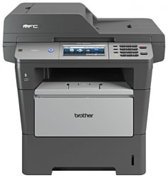
Brother MFC-8950DW
Рейтинг
Снят с производства
Тип устройства
МФУ
Технология печати
лазерная
Макс. формат
A4
Число страниц в месяц
100000
Скорость печати
A4
40
Цветность печати
черно-белая
Общие характеристики |
|
---|---|
Макс. формат |
A4 |
Размещение |
настольный |
Технология печати |
лазерная |
Тип |
лазерный/светодиодный |
Цветность печати |
|
Телефон |
|
Печать фотографий |
|
Тип устройства |
МФУ |
Факс |
![]() |
Копир |
![]() |
Сканер |
![]() |
Число страниц в месяц |
100 000 |
Область применения |
большой офис |
Принтер |
|
Прямая печать |
![]() |
Двусторонняя печать |
![]() |
Печать без полей |
|
Пигментные чернила |
|
Время разогрева |
3 |
Макс, разрешение для ч/б печати |
|
По X | 1 200 |
По Y | 1 200 |
Скорость ч/б печати |
|
A4 | 40 |
Время выхода первого отпечатка |
|
Ч/б | 8,5 |
Копир |
|
Макс, количество копий за цикл |
99 |
Шаг масштабирования |
0,01 |
Время выхода первой копии |
10,5 |
Значение масштаба |
|
Минимальное | 0,25 |
Максимальное | 4 |
Макс, разрешение (ч/б) |
|
По Y | 600 |
По X | 1 200 |
По Y | 1 200 |
Сканер |
|
Макс. формат оригинала |
A4 |
Глубина цвета |
48 бит |
Устройство автоподачи оригиналов |
двустороннее |
Стандарт WIA |
![]() |
Отправка изображения по e-mail |
![]() |
Стандарт TWAIN |
![]() |
Слайд-адаптер |
|
Оттенки серого |
256 |
Тип сканера |
планшетный/протяжный |
Емкость устройства автоподачи оригиналов |
50 |
Макс, размер сканирования |
|
По X | 216 |
По Y | 356 |
Разрешение сканера |
|
По Х (улучшенное) | 19 200 |
По Y (улучшенное) | 19 200 |
По Х | 1 200 |
Расходные материалы |
|
Количество картриджей |
1 |
Ресурс фотобарабана |
30 000 |
Ресурс ч/б картриджа/тонера |
8 000 |
Печать на: |
|
Пленках |
![]() |
Карточках |
![]() |
Этикетках |
![]() |
Глянцевой бумаге |
![]() |
Конвертах |
![]() |
Матовой бумаге |
![]() |
Фотобумаге |
|
Рулоне |
|
CD/DVD |
|
Плотность бумаги |
|
Максимальная | 163 |
Минимальная | 60 |
Факс |
|
PC Fax |
![]() |
Цветной |
|
Память |
500 |
Макс, скорость передачи данных |
33,6 Кбит/с |
Телефон |
|
Автоответчик |
|
Стандарт DECT |
|
Проводная трубка |
|
Caller ID |
|
АОН |
|
Беспроводная трубка |
|
Спикерфон |
|
Шрифты и языки управления |
|
Языки управления |
|
![]() |
|
PCL 6 |
![]() |
PostScript |
![]() |
PostScript 3 |
![]() |
PCL 5e |
|
PostScript 2 |
|
PCL 5c |
|
PPDS |
|
Количество установленных шрифтов |
|
PostScript | 66 |
PCL | 78 |
Лотки |
|
Емкость лотка ручной подачи |
50 |
Подача бумаги |
|
Стандартная | 550 |
Вывод бумаги |
|
Стандартный | 150 |
Финишер |
|
Степлер |
|
Сортер |
|
Брошюровщик |
|
Интерфейсы |
|
Ethernet (RJ-45) |
![]() |
Wi-Fi 802.11n |
![]() |
Wi-Fi |
![]() |
USB |
![]() |
Веб-интерфейс |
![]() |
Устройство для чтения карт памяти |
|
FireWire (IEEE 1394) |
|
Bluetooth |
|
LPT |
|
Инфракрасный порт |
|
RS-232 |
|
Версия USB |
2,0 |
Память/Процессор |
|
Макс, объем памяти |
384 |
Объем памяти |
128 |
Процессор |
StarSapphire |
Частота процессора |
400 |
Дополнительная информация |
|
Работа от аккумулятора |
|
Диагональ дисплея |
5 |
Экран |
|
Поддержка ОС |
|
Linux |
![]() |
Mac OS |
![]() |
Windows |
![]() |
DOS |
|
Потребляемая мощность |
|
При работе | 694 |
В режиме ожидания | 9,8 |
Уровень шума |
|
В режиме ожидания | 37 |
При работе | 59 |
Габариты |
|
Высота |
477 |
Вес |
17,7 |
Глубина |
415 |
Ширина |
491 |
Модули
PAPER TRAY
FRAME L and DRIVE UNIT
DOCUMENT SCANNER
COVERS and LABELS
LOWER TRAY
PCB
PERIODICAL MAINTENANCE PARTS
ADF
FRAME
FUSER UNIT
PANEL
LASER UNIT
PAPER FEEDER
FRAME L
DUPLEX
PAPER EJECT
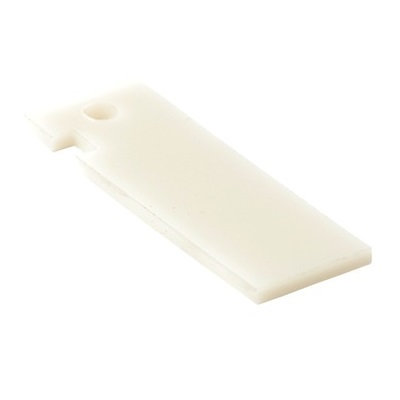
Детали COVERS and LABELS
Деталь: | PAPER TRAY 1 (250 sheets) (SP), DCP-8110DN/8150DN/8155DN/MFC-8510DN/8515DN/8520DN/8710DW/8910DW |
Парткод: | LY5724001 |
Деталь: | PAPER TRAY 1 (500 sheets) (SP), DCP-8250DN/MFC-8950DW/8950DWT |
Парткод: | LY5727001 |
Деталь: | GEAR Z22M10 |
Парткод: | LY4243001 |
Деталь: | IDLE GEAR Z18M10 |
Парткод: | LY4242001 |
Деталь: | LIFT GEAR Z27M10, DCP-8110DN/8150DN/8155DN/ MFC-8510DN/8515DN/8520DN/8710DW/8910DW |
Парткод: | LY4241001 |
Деталь: | LIFT GEAR Z48M10, DCP-8250DN/MFC-8950DW/8950DWT |
Парткод: | LY4516001 |
Деталь: | MAIN FRAME L ASSY (SP), DCP-8110DN/MFC-8510DN FOR US |
Парткод: | LX9887001 |
Деталь: | MAIN FRAME L ASSY (SP), DCP-8110DN/MFC-8510DN EXCEPT FOR US, DCP-8150DN/8155DN/8250DN/MFC-8515DN/8520DN//8710DW/8910DW/8950DW/8950DWT FOR ALL COUNTRIES |
Парткод: | LX9888001 |
Деталь: | BACK COVER SWITCH HARNESS ASSY |
Парткод: | LV0768001 |
Деталь: | TONER SENSOR PCB ASSY |
Парткод: | LV0766001 |
Деталь: | DUPLEX SOLENOID |
Парткод: | LX9115001 |
Деталь: | MP SOLENOID |
Парткод: | LY4393001 |
Деталь: | FUSER DRIVE GEAR 39 |
Парткод: | LY4450001 |
Цена: | 410 ₽ |
Деталь: | NEW TONER ACTUATOR |
Парткод: | LY4454001 |
Деталь: | DEVELOP CLUTCH 51R |
Парткод: | LY4408001 |
Деталь: | DEVELOP ONE WAY CLUTCH 53 |
Парткод: | LY4409001 |
Деталь: | LT DRIVE GEAR 29 |
Парткод: | LY4398001 |

Деталь: | DEVELOP JOINT GEAR 37 |
Парткод: | LY4382001 |
Цена: | 150 ₽ |

Деталь: | DEVELOP JOINT |
Парткод: | LY4380001 |
Цена: | 1 000 ₽ |
Деталь: | MAIN MOTOR ASSY (SP) |
Парткод: | LY5383001 |
Деталь: | INTERNAL TEMPERATURE THERMISTOR |
Парткод: | LT0132001 |
Деталь: | DOCUMENT SCANNER UNIT (SP), DCP-8110DN/MFC-8510DN/8515DN/8520DN |
Парткод: | LX9786001 |

Деталь: | DOCUMENT SCANNER UNIT (SP), DCP-8250DN/MFC-8950DW/8950DWT |
Парткод: | LX9792001 |
Цена: | 14 300 ₽ |
Деталь: | DOCUMENT SCANNER UNIT (SP), DCP-8150DN/8155DN/MFC-8710DW/8910DW |
Парткод: | LX9791001 |
Деталь: | FIRST SIDE CIS UNIT |
Парткод: | LT1713001 |
Цена: | 2 600 ₽ |
Деталь: | FIRST SIDE CIS FLAT CABLE, DCP-8110DN/MFC-8510DN/8515DN/8520DN |
Парткод: | LT1816001 |
Деталь: | FIRST SIDE CIS FLAT CABLE, DCP-8150DN/8155DN/8250DN/ MFC-8710DW/8910DW/8950DW/8950DWT |
Парткод: | LT1712001 |
Деталь: | ADF CLEAN UP LABEL, DCP-8110DN/8150DN/MFC-8510DN/8515DN/8710DW |
Парткод: | LX5186001 |
Деталь: | ADF CLEAN UP LABEL, DCP-8155DN/8250DN/MFC-8520DN/8910DW/8950DW/8950DWT |
Парткод: | LX7422001 |
Деталь: | JOINT COVER, DCP-8110DN/8150DN/8155DN |
Парткод: | LX9113001 |
Деталь: | JOINT COVER, DCP-8250DN |
Парткод: | LX9060001 |
Деталь: | JOINT COVER, MFC-8510DN/8520DN/8710DW EXCEPT FOR CHN, MFC-8910DW FOR US/CAN |
Парткод: | LX9147001 |
Деталь: | JOINT COVER, MFC-8510DN/8515DN/8520DN FOR CHN, MFC-8910DW FOR ASA, MFC-8950DW/8950DWT FOR ALL COUNTRIES |
Парткод: | LX9138001 |
Деталь: | USB HOST PCB ASSY |
Парткод: | LV0531001 |
Деталь: | TAPTITE BIND B M4X12 |
Парткод: | LU5693001 |
Деталь: | SPEAKER UNIT |
Парткод: | LT1733001 |
Деталь: | SIDE COVER R ASSY, DCP-8110DN/8150DN/8155DN |
Парткод: | LX9109001 |
Деталь: | SIDE COVER R ASSY, DCP-8250DN |
Парткод: | LX9140001 |
Деталь: | SIDE COVER R ASSY, MFC-8510DN/8515DN/8520DN/8710DW/8910DW |
Парткод: | LX9004001 |
Деталь: | SIDE COVER R ASSY, MFC-8950DW/8950DWT |
Парткод: | LX9006001 |
Деталь: | SIDE COVER L, DCP-8110DN/8150DN/8155DN |
Парткод: | LX9108001 |
Деталь: | SIDE COVER L, DCP-8250DN |
Парткод: | LX9141001 |
Деталь: | SIDE COVER L, MFC-8510DN/8515DN/8520DN/8710DW/8910DW |
Парткод: | LX9005001 |
Деталь: | SIDE COVER L, MFC-8950DW/8950DWT |
Парткод: | LX9007001 |
Деталь: | CORD HOOK, MFC-8510DN/8515DN/8520DN/8710DW/8910DW/8950DW/8950DWT |
Парткод: | LX9044001 |
Деталь: | ACCESS COVER |
Парткод: | LY4463001 |
Деталь: | FUSER COVER |
Парткод: | LY4580001 |
Деталь: | BACK COVER |
Парткод: | LY4176001 |
Деталь: | OUTER CHUTE |
Парткод: | LY4175001 |
Деталь: | MP PAPER GUIDE ASSY, DCP-8110DN/8150DN/8155DN/ MFC-8510DN/8520DN/8710DW/8910DW/8950DW/8950DWT FOR US/CAN/GER/UK/ITA/FRA/BEL/NLD/CHN/ASA/IBR |
Парткод: | LY4174002 |
Деталь: | MP PAPER GUIDE ASSY, DCP-8250DN/MFC-8515DN/8950DW/8950DWT FOR GER/UK/FRA/BEL/NLD/CHE/ITA/CHN/PND |
Парткод: | LY4174003 |
Деталь: | MP COVER ASSY(SP), DCP-8110DN/8150DN/8155DN/ MFC-8510DN/8520DN/8710DW/8910DW/8950DW/8950DWT FOR |
Парткод: | LY5327002 |
Деталь: | MP COVER ASSY(SP), DCP-8250DN/MFC-8515DN/8950DW/8950DWT FOR GER/UK/FRA/BEL/NLD/CHE/ITA/CHN/PND |
Парткод: | LY5327003 |
Деталь: | FRONT COVER ASSY, DCP-8110DN/8150DN/8155DN/ MFC-8510DN/8520DN/8710DW/8910DW/8950DW/8950DWT FOR US/CAN/GER/UK/ITA/FRA/BEL/NLD/IBR |
Парткод: | LX9076001 |
Деталь: | FRONT COVER ASSY, DCP-8250DN/MFC-8950DW/8950DWT FOR GER/UK/FRA/BEL/NLD/CHE/ITA/PND |
Парткод: | LX9076002 |
Деталь: | FRONT COVER ASSY, MFC-8510DN/8520DN FOR CHN |
Парткод: | LX9312001 |
Деталь: | FRONT COVER ASSY, MFC-8515DN FOR CHN |
Парткод: | LX9312002 |
Деталь: | FRONT COVER ASSY, MFC-8910DW FOR ASA |
Парткод: | LX9878001 |
Деталь: | EXT CAP, MFC-8510DN/8520DN/8710DW/8910DW/8950DW/8950DWT FOR US/CAN/CHE/ASA/PND/IBR |
Парткод: | LE8842001 |
Деталь: | MJ COVER EXT, MFC-8510DN/8515DN/8520DN/8950DW/8950DWT FOR GER/UK/FRA/BEL/NLD/ITA/CHN |
Парткод: | UF5745000 |
Деталь: | WIRELESS LAN PCB ASSY, MFC-8710DW/8910DW/8950DW/8950DWT |
Парткод: | LT2155001 |
Деталь: | LABEL PROCESS OP US 26X209, DCP-8110DN/8150DN/8155DN/ MFC-8510DN/8710DW/8910DW FOR US/CAN |
Парткод: | LX9172001 |
Деталь: | LABEL PROCESS OP 26X209, DCP-8110DN/8250DN/MFC-8510DN/8515DN/8520DN/ 8910DW/8950DW/8950DWT FOR GER/UK/FRA/BEL/NLD/CHE/ITA/ASA/PND/IBR |
Парткод: | LX9173001 |
Деталь: | LABEL PROCESS OP US FS 26X209, MFC-8950DW/8950DWT FOR US |
Парткод: | LX9174001 |
Деталь: | LABEL PROCESS OP CHN 26X209, MFC-8510DN/8515DN/8520DN FOR CHN |
Парткод: | LX9223001 |
Деталь: | LABEL H CAUTION REAR 14X72 |
Парткод: | LY4574001 |
Деталь: | LABEL REAR JAM 17X55 |
Парткод: | LY4690001 |
Деталь: | PAPER STOPPER, DCP-8110DN/8150DN/8155DN/ MFC-8510DN/8520DN/8710DW/8910DW/8950DW/8950DWT FOR US/CAN/GER/UK/ITA/FRA/BEL/NLD/CHN/ASA/IBR |
Парткод: | LY4160001 |
Деталь: | PAPER STOPPER, DCP-8250DN/MFC-8515DN/8950DW/8950DWT FOR GER/UK/FRA/BEL/NLD/CHE/ITA/CHN/PND |
Парткод: | LY4160002 |
Деталь: | T2 BACK COVER, MFC-8950DWT |
Парткод: | LY4534001 |
Деталь: | T2 CLUTCH, MFC-8950DWT |
Парткод: | LY4335001 |
Деталь: | T2 PAPER FEED ACTUATOR, MFC-8950DWT |
Парткод: | LY4562001 |
Деталь: | T2 PAPER FEED ACTUATOR SPRING, MFC-8950DWT |
Парткод: | LY4561001 |
Деталь: | T2 PAPER FEED SENSOR PCB ASSY, MFC-8950DWT |
Парткод: | LV0812001 |
Деталь: | PAPER TRAY 2 (SP), MFC-8950DWT |
Парткод: | LY5947001 |
Деталь: | T2 FRONT COVER ASSY, MFC-8950DWT |
Парткод: | LY4533001 |
Деталь: | T2 SIDE COVER L, MFC-8950DWT |
Парткод: | LY4530001 |
Деталь: | T2 SIDE COVER R, MFC-8950DWT |
Парткод: | LY4529001 |
Деталь: | T2 RELAY PCB ASSY, MFC-8950DWT |
Парткод: | LV0814001 |
Деталь: | LT CONNECTOR ASSY (T2), MFC-8950DWT |
Парткод: | LY5498001 |
Деталь: | GEAR Z22M10, MFC-8950DWT |
Парткод: | LY4243001 |
Деталь: | IDLE GEAR Z18M10, MFC-8950DWT |
Парткод: | LY4242001 |
Деталь: | LIFT GEAR Z48M10, MFC-8950DWT |
Парткод: | LY4516001 |
Деталь: | MAIN PCB ASSY, DCP-8110DN |
Парткод: | LT1790001 |
Деталь: | MAIN PCB ASSY, DCP-8150DN |
Парткод: | LT1715001 |
Деталь: | MAIN PCB ASSY, DCP-8155DN |
Парткод: | LT1795001 |
Деталь: | MAIN PCB ASSY, DCP-8250DN |
Парткод: | LT1763002 |
Деталь: | MAIN PCB ASSY, MFC-8510DN FOR US |
Парткод: | LT1791001 |
Деталь: | MAIN PCB ASSY, MFC-8510DN EXCEPT FOR US/CHN |
Парткод: | LT1791002 |
Деталь: | MAIN PCB ASSY, MFC-8510DN/8515DN FOR CHN |
Парткод: | LT1791004 |
Деталь: | MAIN PCB ASSY, MFC-8520DN EXCEPT FOR CHN |
Парткод: | LT1792002 |
Деталь: | MAIN PCB ASSY, MFC-8520DN FOR CHN |
Парткод: | LT1792004 |
Деталь: | MAIN PCB ASSY, MFC-8710DW |
Парткод: | LT1796001 |
Деталь: | MAIN PCB ASSY, MFC-8950DW/8950DWT FOR US |
Парткод: | LT1703001 |
Деталь: | MAIN PCB ASSY, MFC-8950DW/8950DWT EXCEPT FOR US |
Парткод: | LT1703002 |
Деталь: | MAIN PCB ASSY, MFC-8910DW FOR US/CAN |
Парткод: | LT1760001 |
Деталь: | MAIN PCB ASSY, MFC-8910DW FOR ASA |
Парткод: | LT1760002 |
Деталь: | NCU PCB ASSY, MFC-8510DN/8710DW/8910DW/8950DW/8950DWT FOR US |
Парткод: | LT0867001 |
Деталь: | NCU PCB ASSY, MFC-8710DW/8910DW FOR CAN |
Парткод: | LT0867003 |
Деталь: | NCU PCB ASSY, MFC-8510DN/8515DN/8520DN/8710DW/8950DW/8950DWT EXCEPT FOR US/CAN/CHN |
Парткод: | LT1168001 |
Деталь: | NCU PCB ASSY, MFC-8510DN/8515DN/8520DN FOR CHN |
Парткод: | LT1324001 |
Деталь: | NCU PCB ASSY, MFC-8910DW FOR ASA |
Парткод: | LT1328001 |
Деталь: | LOW VOLTAGE POWER SUPPLY PCB ASSY FOR US/CAN |
Парткод: | LT1706001 |
Деталь: | LOW VOLTAGE POWER SUPPLY PCB ASSY EXCEPT FOR US/CAN/CHN |
Парткод: | LT1756001 |
Деталь: | LOW VOLTAGE POWER SUPPLY FOR CHN |
Парткод: | LT1830001 |
Деталь: | HIGH VOLTAGE POWER SUPPLY PCB ASSY |
Парткод: | LV0806001 |
Деталь: | PAPER FEEDING KIT 1/2 (SP) |
Парткод: | LY5384001 |
Деталь: | MP PAPER FEEDING KIT (SP) |
Парткод: | LY5385001 |
Деталь: | ADF UNIT(SP), DCP-8110DN/MFC-8510DN/8515DN |
Парткод: | LX9785001 |
Деталь: | ADF UNIT(SP), DCP-8150DN/MFC-8710DW |
Парткод: | LX9789001 |
Деталь: | ADF UNIT(SP), DCP-8155DN/8250DN/MFC-8910DW/8950DW/8950DWT |
Парткод: | LX9790001 |
Деталь: | ADF UNIT(SP), MFC-8520DW |
Парткод: | LX9972001 |
Деталь: | HINGE ASSY L, DCP-8110DN/MFC-8510DN/8515DN |
Парткод: | LX5255001 |
Деталь: | HINGE ASSY L, DCP-8155DN/8250DN/MFC-8910DW/8950DW/8950DWT |
Парткод: | LX4269002 |
Деталь: | HINGE ASSY L, DCP-8150DN/MFC-8710DW |
Парткод: | LX9095001 |
Деталь: | HINGE ASSY L, MFC-8520DN |
Парткод: | LX4126002 |
Деталь: | TAPTITE CUP S M3X12 |
Парткод: | 087321217 |
Деталь: | TAPTITE CUP B M3X10 |
Парткод: | 087311016 |
Деталь: | HINGE R, DCP-8110DN/MFC-8510DN/8515DN/8520DN |
Парткод: | LX5180001 |
Деталь: | HINGE R, DCP-8150DN/8155DN/8250DN/MFC-8710DW/8910DW/8950DW/8950DWT |
Парткод: | LS8154002 |
Деталь: | HINGE R SUPPORT |
Парткод: | LS8155002 |
Деталь: | FFC HOLDER ASSY(SP) |
Парткод: | LX9717001 |
Деталь: | ADF EMBLEM, DCP-8110DN/8150DN/8155DN FOR US |
Парткод: | LX5211001 |
Деталь: | ADF EMBLEM MFC-8510DN/8710DW/8910DW/8950DW/8950DWT FOR US/CAN |
Парткод: | LX4202002 |
Деталь: | ADF EMBLEM, DCP-8110DN/8250DN FOR GER/UK/FRA/BEL/NLD/CHE/ITA/PND |
Парткод: | LX4197002 |
Деталь: | ADF EMBLEM, MFC-8510DN/8515DN/8520DN/8910DW/8950DW/8950DWT FOR GER/UK/FRA/BEL/NLD/CHE/ITA/CHN/ASA/PND/IBR |
Парткод: | LX4196002 |
Деталь: | DOCUMENT COVER ASSY, DCP-8110DN/MFC-8510DN/8515DN/8520DN |
Парткод: | LX9298001 |
Деталь: | DOCUMENT COVER ASSY, DCP-8150DN/8155DN/8250DN/MFC-8710DW/8910DW/8950DW/8950DWT |
Парткод: | LX9067001 |
Деталь: | ADF MOTOR ASSY, DCP-8110DN/MFC-8510DN/8515DN/8520DN |
Парткод: | LX5307001 |
Деталь: | ADF MOTOR ASSY, DCP-8150DN/8155DN/8250DN/ MFC-8710DW/8910DW/8950DW/8950DWT |
Парткод: | LX9215001 |
Деталь: | SCREW PAN (S/P WASHER) M3X6 |
Парткод: | 0A4300606 |
Деталь: | FIRST SIDE DOCUMENT SCANNING POSITION SENSOR PCB ASSY |
Парткод: | LG6753001 |
Деталь: | SECOND SIDE DOCUMENT SCANNING POSITION SENSOR PCB ASSY, DCP-8155DN/8250DN/MFC-8520DN/8910DW/8950DW/8950DWT |
Парткод: | LG6753001 |
Деталь: | ADF COVER/ DOCUMENT DETECTION SENSOR PCB ASSY |
Парткод: | LT1120001 |
Деталь: | DOCUMENT FEED ROLLER ASSY1, DCP-8110DN/MFC-8510DN/8515DN/8520DN |
Парткод: | LX8675001 |
Деталь: | DOCUMENT FEED ROLLER ASSY1, DCP-8150DN/8155DN/8250DN/ MFC-8710DW/8910DW/8950DW/8950DWT |
Парткод: | LX9320001 |
Деталь: | ADF SEPARATION PAD HOLDER ASSY, DCP-8110DN/MFC-8510DN/8515DN/8520DN |
Парткод: | LX9751001 |
Деталь: | ADF SEPARATION PAD HOLDER, DCP-8150DN/8155DN/8250DN/ MFC-8710DW/8910DW/8950DW/8950DWT |
Парткод: | LX4320002 |

Деталь: | ADF SEPARATION PAD, DCP-8150DN/8155DN/8250DN/ MFC-8710DW/8910DW/8950DW/8950DWT |
Парткод: | LX9748001 |
Цена: | 850 ₽ |
Деталь: | SEPARATION SUPPORT FILM, DCP-8150DN/8155DN/8250DN/ MFC-8710DW/8910DW/8950DW/8950DWT |
Парткод: | LX4777001 |
Деталь: | SUPPORT FILM, DCP-8150DN/8155DN/8250DN/ MFC-8710DW/8910DW/8950DW/8950DWT |
Парткод: | LX4652001 |
Деталь: | SECOND SIDE CIS UNIT, DCP-8155DN/8250DN/MFC-8910DW/8950DW/8950DWT |
Парткод: | LT1704001 |
Деталь: | SECOND SIDE CIS UNIT, MFC-8520DN |
Парткод: | LT1783001 |
Деталь: | SECOND SIDE CIS FLAT CABLE, DCP-8155DN/8250DN/ MFC-8910DW/8950DW/8950DWT |
Парткод: | LT1741001 |
Цена: | 290 ₽ |
Деталь: | SECOND SIDE CIS FLAT CABLE, MFC-8520DN |
Парткод: | LT2006001 |
Деталь: | CIS GLASS, DCP-8155DN/8250DN/MFC-8520DN/8910DW/8950DW/8950DWT |
Парткод: | LX4368001 |
Деталь: | CIS GLASS STOPPER, DCP-8155DN/8250DN/MFC-8520DN/8910DW/8950DW/8950DWT |
Парткод: | LX4098001 |
Деталь: | CIS SPRING, DCP-8155DN/8250DN/MFC-8520DN/8910DW/8950DW/8950DWT |
Парткод: | LX4099001 |
Деталь: | CIS SPACER, DCP-8155DN/8250DN/MFC-8520DN/8910DW/8950DW/8950DWT |
Парткод: | LX9030001 |

Деталь: | DOCUMENT SEPARATE ROLLER ASSY, DCP-8110DN/MFC-8510DN/8515DN |
Парткод: | LX9296001 |
Цена: | 1 700 ₽ |

Деталь: | DOCUMENT SEPARATE ROLLER ASSY, DCP-8155DN/8250DN/ MFC-8910DW/8950DW/8950DWT |
Парткод: | LX9358001 |
Цена: | 2 500 ₽ |
Деталь: | DOCUMENT SEPARATE ROLLER ASSY, DCP-8150DN/MFC-8710DW |
Парткод: | LX9098001 |

Деталь: | DOCUMENT SEPARATE ROLLER ASSY, MFC-8520DN |
Парткод: | LX9297001 |
Цена: | 1 600 ₽ |
Деталь: | GEAR COVER, DCP-8110DN/MFC-8510DN/8515DN/8520DN |
Парткод: | LX5041001 |
Деталь: | GEAR COVER, DCP-8150DN/8155DN/8250DN/ MFC-8710DW/8910DW/8950DW/8950DWT |
Парткод: | LX4264002 |
Деталь: | ADF COVER ASSY, DCP-8110DN/MFC-8510DN/8515DN |
Парткод: | LX5042001 |
Деталь: | ADF COVER ASSY, DCP-8155DN/8250DN/MFC-8910DW/8950DW/8950DWT |
Парткод: | LX9360001 |
Деталь: | ADF COVER ASSY, DCP-8150DN/MFC-8710DW |
Парткод: | LX9096001 |
Деталь: | ADF COVER ASSY, MFC-8520DN |
Парткод: | LX4118002 |
Деталь: | ADF DOCUMENT SUPPORT, DCP-8110DN/MFC-8510DN/8515DN/8520DN |
Парткод: | LX5371002 |
Деталь: | ADF DOCUMENT SUPPORT, DCP-8150DN/8155DN/8250DN/ MFC-8710DW/8910DW/8950DW/8950DWT |
Парткод: | LX4268002 |
Деталь: | ADF DOCUMENT OUTPUT SUPPORT FLAP, DCP-8110DN/MFC-8510DN/8515DN/8520DN |
Парткод: | LX4184002 |
Цена: | 440 ₽ |
Деталь: | ADF DOCUMENT OUTPUT SUPPORT FLAP, DCP-8150DN/8155DN/8250DN/ MFC-8710DW/8910DW/8950DW/8950DWT |
Парткод: | LX4267002 |
Деталь: | HINGE ARM R |
Парткод: | LS8141002 |
Деталь: | MAIN FAN |
Парткод: | LY4367001 |
Деталь: | TONER LED PCB ASSY |
Парткод: | LT2008001 |
Деталь: | AIR DUCT |
Парткод: | LY4350001 |
Деталь: | FILTER |
Парткод: | LY5321001 |
Деталь: | T1 PAPER FEED ACTUATOR |
Парткод: | LY4562001 |
Деталь: | T1 PAPER FEED ACTUATOR SPRING |
Парткод: | LY4561001 |
Деталь: | T1 PAPER FEED SENSOR PCB ASSY |
Парткод: | LV0812001 |
Деталь: | FEED GROUND SPRING |
Парткод: | LY4331001 |
Деталь: | LT CONNECTOR (T1) |
Парткод: | LM9266001 |
Деталь: | T1 CLUTCH |
Парткод: | LY4335001 |

Деталь: | REGISTRATION CLUTCH |
Парткод: | LY4332001 |
Цена: | 1 200 ₽ |
Деталь: | RELAY FRONT PCB ASSY |
Парткод: | LV0773001 |
Деталь: | LAN PORT CAP |
Парткод: | LY0872001 |
Деталь: | FUSER UNIT 115V (SP) |
Парткод: | LY5606001 |
Деталь: | FUSER UNIT 230V (SP) |
Парткод: | LY5610001 |
Деталь: | TAPTITE PAN B M4X14 |
Парткод: | LJ0395001 |
Деталь: | CONTROL PANEL ASSY, DCP-8110DN/8150DN/8155DN |
Парткод: | LX9094001 |
Деталь: | CONTROL PANEL ASSY, DCP-8250DN |
Парткод: | LX9142001 |
Деталь: | CONTROL PANEL ASSY, MFC-8510DN/8520DN/8710DW/8910DW EXCEPT FOR CHN |
Парткод: | LX9148001 |
Деталь: | CONTROL PANEL ASSY, MFC-8510DN/8515DN/8520DN FOR CHN |
Парткод: | LX9225001 |
Деталь: | CONTROL PANEL ASSY, MFC-8950DW/8950DWT |
Парткод: | LX9054001 |
Деталь: | PANEL COVER ASSY, DCP-8110DN FOR US/UK |
Парткод: | LX9182001 |
Деталь: | PANEL COVER ASSY, DCP-8150DN FOR US |
Парткод: | LX9090001 |
Деталь: | PANEL COVER ASSY, DCP-8155DN FOR US |
Парткод: | LX9184001 |
Деталь: | PANEL COVER ASSY, MFC-8510DN FOR US |
Парткод: | LX9186001 |
Деталь: | PANEL COVER ASSY, MFC-8510DN FOR UK |
Парткод: | LX9325001 |
Деталь: | PANEL COVER ASSY, MFC-8520DN FOR UK |
Парткод: | LX9228001 |
Деталь: | PANEL COVER ASSY, MFC-8710DW FOR US/CAN |
Парткод: | LX9640001 |
Деталь: | PANEL COVER ASSY, MFC-8910DW FOR US/CAN/ASA |
Парткод: | LX9153001 |
Деталь: | PANEL COVER ASSY, DCP-8110DN FOR GER |
Парткод: | LX9718001 |
Деталь: | PANEL COVER ASSY, MFC-8510DN FOR GER |
Парткод: | LX9594001 |
Деталь: | PANEL COVER ASSY, MFC-8520DN FOR GER |
Парткод: | LX9795001 |
Деталь: | PANEL COVER ASSY, DCP-8110DN FOR FRA/BEL/NLD (ENGLISH) |
Парткод: | LX9733001 |
Деталь: | PANEL COVER ASSY, MFC-8510DN FOR FRA/BEL/NLD (ENGLISH) |
Парткод: | LX9651001 |
Деталь: | PANEL COVER ASSY, MFC-8520DN FOR FRA/BEL/NLD (ENGLISH) |
Парткод: | LX9806001 |
Деталь: | PANEL COVER ASSY, DCP-8110DN FOR FRA/BEL/NLD (FRENCH) |
Парткод: | LX9730001 |
Деталь: | PANEL COVER ASSY, MFC-8510DN FOR FRA/BEL/NLD (FRENCH) |
Парткод: | LX9635001 |
Деталь: | PANEL COVER ASSY, MFC-8520DN FOR FRA/BEL/NLD (FRENCH) |
Парткод: | LX9803001 |
Деталь: | PANEL COVER ASSY, DCP-8110DN FOR FRA/BEL/NLD (DUTCH) |
Парткод: | LX9734001 |
Деталь: | PANEL COVER ASSY, MFC-8510DN FOR FRA/BEL/NLD (DUTCH) |
Парткод: | LX9652001 |
Деталь: | PANEL COVER ASSY, MFC-8520DN FOR FRA/BEL/NLD (DUTCH) |
Парткод: | LX9807001 |
Деталь: | PANEL COVER ASSY, DCP-8110DN FOR ITA |
Парткод: | LX9731001 |
Деталь: | PANEL COVER ASSY, MFC-8510DN FOR ITA |
Парткод: | LX9636001 |
Деталь: | PANEL COVER ASSY, MFC-8520DN FOR ITA |
Парткод: | LX9805001 |
Деталь: | PANEL COVER ASSY, MFC-8510DN FOR CHN |
Парткод: | LX9226001 |
Деталь: | PANEL COVER ASSY, MFC-8515DN FOR CHN |
Парткод: | LX9291001 |
Деталь: | PANEL COVER ASSY, MFC-8520DN FOR CHN |
Парткод: | LX9229001 |
Деталь: | PANEL COVER ASSY, DCP-8110DN FOR IBR |
Парткод: | LX9732001 |
Деталь: | PANEL COVER ASSY, MFC-8510DN FOR IBR |
Парткод: | LX9638001 |
Деталь: | PANEL COVER ASSY, MFC-8520DN FOR IBR |
Парткод: | LX9808001 |
Деталь: | PRINTED PANEL COVER, MFC-8950DW/8950DWT FOR US |
Парткод: | LX9046001 |
Деталь: | PRINTED PANEL COVER, MFC-8950DW/8950DWT FOR GER |
Парткод: | LX9398001 |
Деталь: | PRINTED PANEL COVER, MFC-8950DW/8950DWT FOR GER/CHE (GERMAN) |
Парткод: | LX9400001 |
Деталь: | PRINTED PANEL COVER, DCP-8250DN FOR UK/FRA/BEL/NLD (ENGLISH) |
Парткод: | LX9390001 |
Деталь: | PRINTED PANEL COVER, MFC-8950DW/8950DWT FOR UK/FRA/BEL/NLD (ENGLISH) |
Парткод: | LX9409001 |
Деталь: | PRINTED PANEL COVER, DCP-8250DN FOR FRA/BEL/NLD/CHE (FRENCH) |
Парткод: | LX9385001 |
Деталь: | PRINTED PANEL COVER, MFC-8950DW/8950DWT FOR FRA/BEL/NLD/CHE (FRENCH) |
Парткод: | LX9406001 |
Деталь: | PRINTED PANEL COVER, DCP-8250DN FOR FRA/BEL/NLD (DUTCH) |
Парткод: | LX9387001 |
Деталь: | PRINTED PANEL COVER, MFC-8950DW/8950DWT FOR FRA/BEL/NLD (DUTCH) |
Парткод: | LX9410001 |
Деталь: | PRINTED PANEL COVER, DCP-8250DN FOR CHE (GERMAN) |
Парткод: | LX9840001 |
Деталь: | PRINTED PANEL COVER, DCP-8250DN FOR ITA/IBR (ITALIAN) |
Парткод: | LX9380001 |
Деталь: | PRINTED PANEL COVER, DCP-8250DN FOR ITA/IBR (SPANISH) |
Парткод: | LX9382001 |
Деталь: | PRINTED PANEL COVER, MFC-8950DW/8950DWT FOR ITA/IBR (ITALIAN) |
Парткод: | LX9407001 |
Деталь: | PRINTED PANEL COVER, MFC-8950DW/8950DWT FOR ITA/IBR (SPANISH) |
Парткод: | LX9408001 |
Деталь: | PRINTED PANEL COVER, DCP-8250DN FOR PND |
Парткод: | LX9552001 |
Деталь: | PRINTED PANEL COVER, MFC-8950DW/8950DWT FOR PND |
Парткод: | LX9399001 |
Деталь: | TAPTITE BIND B M4X12 |
Парткод: | LU5693001 |
Деталь: | PANEL COVER, DCP-8250DN |
Парткод: | LX9143001 |
Деталь: | PANEL COVER, MFC-8950DW/8950DWT |
Парткод: | LX9053001 |
Деталь: | RUBBER KEY R, DCP-8110DN/8150DN/8155DN/ MFC-8510DN/8515DN/8520DN/8710DW/8910DW |
Парткод: | LX9093001 |
Деталь: | RUBBER KEY R, DCP-8250DN |
Парткод: | LX9144001 |
Деталь: | RUBBER KEY R, MFC-8950DW/8950DWT |
Парткод: | LX9052001 |
Деталь: | RUBBER KEY C, DCP-8110DN/8150DN/8155DN |
Парткод: | LX9092001 |
Деталь: | RUBBER KEY C, MFC-8510DN/8515DN/8520DN/8710DW/8910DW |
Парткод: | LX9149001 |
Деталь: | RUBBER KEY L, DCP-8110DN/8150DN/8155DN |
Парткод: | LX9091001 |
Деталь: | RUBBER KEY L, DCP-8250DN/MFC-8950DW/8950DWT |
Парткод: | LX9051001 |
Деталь: | RUBBER KEY L, MFC-8510DN/8515DN/8520DN/8710DW/8910DW |
Парткод: | LX9150001 |
Деталь: | PANEL PCB ASSY, DCP-8110DN/8150DN/8155DN |
Парткод: | LT1716002 |
Деталь: | PANEL PCB ASSY, MFC-8510DN/8520DN/8710DW/8910DW EXCEPT FOR CHN |
Парткод: | LT1716001 |
Деталь: | PANEL PCB ASSY, MFC-8510DN/8515DN/8520DN FOR CHN |
Парткод: | LT1834001 |
Деталь: | LCD, DCP-8110DN/8150DN/8155DN/MFC-8510DN/8520DN/8710DW/8910DW EXCEPT FOR CHN |
Парткод: | A62006001 |
Деталь: | LCD, DCP-8250DN/MFC-8950DW/8950DWT |
Парткод: | A62122001 |
Деталь: | LCD, MFC-8510DN/8515DN/8520DN FOR CHN |
Парткод: | A62027001 |
Деталь: | BACK LIGHT ASSY, DCP-8110DN/8150DN/8155DN/ MFC-8510DN/8515DN/8520DN/8710DW/8910DW |
Парткод: | LT1800001 |
Деталь: | TOUCH PANEL ASSY, DCP-8250DN/MFC-8950DW/8950DWT |
Парткод: | LX9129001 |
Деталь: | TOUCH PANEL PCB ASSY, DCP-8250DN/MFC-8950DW/8950DWT |
Парткод: | LT1742001 |
Деталь: | ADDRESS LABEL, MFC-8510DN/8515DN/8520DN/8710DW/8910DW |
Парткод: | LX9171001 |

Деталь: | LASER UNIT (SP) |
Парткод: | LY4628001 |
Цена: | 14 500 ₽ |
Деталь: | REGISTRATION FRONT ACTUATOR |
Парткод: | LY4311001 |
Деталь: | REGISTRATION REAR ACTUATOR |
Парткод: | LY4310001 |
Деталь: | REGISTRATION ACTUATOR SPRING |
Парткод: | LY4309001 |
Деталь: | REGISTRATION FRONT/REAR SENSOR PCB ASSY |
Парткод: | LV0785001 |
Деталь: | EJECT SENSOR PCB ASSY |
Парткод: | LV0787001 |
Деталь: | MP PAPER EMPTY SENSOR PCB ASSY |
Парткод: | LV0789001 |
Деталь: | MP PAPER EMPTY ACTUATOR 2 |
Парткод: | LY4290001 |
Деталь: | MP PAPER EMPTY ACTUATOR 1 |
Парткод: | LY4289001 |
Деталь: | PANEL UNIT, MFC9840CDW |
Парткод: | LU8566001 |
Цена: | 18 800 ₽ |
Деталь: | Термоплёнка |
Парткод: | DPT-FILM-064 |
Деталь: | Термоплёнка |
Парткод: | FILM-B5450 |

Деталь: | Прижимной вал |
Парткод: | CET2801 |
Цена: | 2 000 ₽ |

Деталь: | Термоплёнка |
Парткод: | CET2800 |
Цена: | 2 100 ₽ |
Деталь: | Термоплёнка |
Парткод: | FF-B5440-1 |
Цена: | 1 000 ₽ |
Коды ошибок
0B00
0C01, 0C02, 0C03, 0C04
0E00
0F00
3600
3B00
4400
5000
5100
5200
5300
5400
5500
5600
5700
5800
5900
6300
6700
6A00
6B00
6C00
6D00
6E00
6F00
7100
7200
7500
7600
7800
7A00
7D00
8000
8300
8400
8500
8800
8900
8A00
8B00
8C00
8D00
9000
9100
9200
9300
9400
9500
9600
9700
9800
9900
9A00
9F01
A000
A100
A200
A300
A400
A500
A600
A700
A800
A900
AC00
AD00
AF00
B000
B700
B800
B900
BB00
BC00
BD00
BF00
C000
C700
C800
C900
CA00
D000
D100
DD00
DE00
E000
E100
E200
E600
EC00
ED00
EE00
EF00
F000
F900
Описание
Error code: | 0B00 |
Description: | There was no response from the panel for the specified time for any reason. |
Causes: | 1 Panel PCB failure. 2 Touch panel PCB failure. 3 Main PCB failure |
Remedy: | 1 Panel PCB failure Replace the panel PCB ASSY. 2 Touch panel PCB failure Replace the touch panel PCB ASSY. 3 Main PCB failure Replace the main PCB ASSY. |
Error code: | 0C01, 0C02, 0C03, 0C04 |
Description: | Log registration failed. |
Causes: | 1 Main PCB failure |
Remedy: | Replace the main PCB ASSY. |
Error code: | 0E00 |
Display: | Print Unable 0E Turn the power off and then back on again. |
Description: | Communication error occurred in the high-voltage power supply PCB ASSY. |
Causes: | 1 Connection failure of the panel PCB harness. 2 Panel PCB failure. 3 Touch panel PCB failure. 4 Main PCB failure. |
Remedy: | 1 Connection failure of the high-voltage power supply PCB harness Reconnect the high-voltage power supply PCB harness. 2 High-voltage power supply PCB failure Replace the high-voltage power supply PCB ASSY. 3 Main PCB failure Replace the main PCB ASSY. |
Error code: | 0F00 |
Description: | The back cover sensor detected that the cover was open in duplex printing mode. |
Causes: | 1 Connection failure of the back cover sensor harness. 2 Back cover sensor attachment failure. 3 Broken rib (on the right inside the back cover) where the back cover switch is pressed. 4 Damaged duplex tray. 5 Back cover sensor failure. 6 Main PCB failure |
Remedy: | 1 Connection failure of the back cover sensor harness Check the connection of the back cover sensor harness, and reconnect it if necessary. 2 Back cover sensor attachment failure Reattach the back cover sensor. 3 Broken rib (on the right inside the back cover) where the back cover switch is pressed Replace the back cover. 4 Damaged duplex tray Replace the duplex tray. 5 Back cover sensor failure Replace the back cover switch harness ASSY. 6 Main PCB failure Replace the main PCB ASSY. |
Error code: | 3600 |
Description: | Scanner sequence error |
Causes: | Defective ISC PWB. |
Remedy: | ISC PWB 1. Execute U021 memory initializing. 2. Replace the ISC PWB and execute U411. |
Error code: | 3B00 |
Display: | Unable to Scan 3B See Troubleshooting in User`s Guide. |
Description: | An error occurred during access to the DRAM in the main PCB. |
Causes: | 1 Main PCB failure |
Remedy: | Replace the main PCB ASSY. |
Error code: | 4400 |
Display: | Supplies Replace Belt |
Description: | Number of pages printed with the belt unit has reached the upper limit. (Printing is not stopped.j |
Causes: | 1 Main PCB failure if the error code remains after replacing with a new belt unit and resetting the belt counter |
Remedy: | < User Check > - Prepare a new belt unit. 1 Main PCB failure if the error code remains after replacing with a new belt unit and resetting the belt counter Replace the main PCB ASSY. |
Error code: | 5000 |
Description: | The number of rotations of the drum unit has reached the life limit. (Printing does not stop.) |
Causes: | 1 Replace the drum unit with a new one and reset the drum counter. If the error display is not cleared, the main PCB is faulty. |
Remedy: | Replace the main PCB ASSY. |
Error code: | 5100 |
Description: | Short-circuited main charger output Five pages have been printed with the main charger output short-circuited. |
Causes: | Drum unit installed incorrectly. Engine PWB installed incorrectly. Defective engine PWB |
Remedy: | Drum unit installed incorrectly. Verify harness is not pinched in the drum unit. Engine PWB installed incorrectly. Verify harness is not pinched in the engine PWB. Defective engine PWB. Replace the engine PWB. |
Error code: | 5200 |
Description: | Printable pages set for paper feeding kit 1 have reached the limit. (Printing does not stop.) |
Causes: | 1 End of life of the fuser unit. 2 Main PCB failure. |
Remedy: | 1 Abrasion of the MP paper feeding kit, paper feeding kit 1 or paper feeding kit 2 Replace the MP paper feeding kit, paper feeding kit 1 or paper feeding kit 2. 2 Main PCB failure Replace the main PCB ASSY. |
Error code: | 5300 |
Description: | Eraser lamp broken detection • The current at the correct level is not detected when ASIC (U8) on the engine controller PWB (KP-992) generates the signal to activate the eraser lamp. |
Causes: | Defective engine controller PWB (KP-992). Defective drum unit (eraser lamp or drum PWB [KP- 813]). Defective harness (2BM2864) between engine controller PWB (KP-992) and drum unit, or poor contact of the connector terminals. |
Remedy: | Replace the engine controller PWB (KP- 992). Replace the drum unit. Check the continuity of the harness (2BM2864). Check the insertion of connectors. |
Error code: | 5400 |
Description: | Printable pages set for the fuser unit have reached the limit. (Printing does not stop.) |
Causes: | 1 End of life of the fuser unit. 2 Main PCB failure. |
Remedy: | 1 End of life of the fuser unit Replace the fuser unit. 2 Main PCB failure Replace the main PCB ASSY. |
Error code: | 5500 |
Description: | Printable pages set for the laser unit have reached the limit. (Printing does not stop.) |
Causes: | 1 End of life of the laser unit. 2 Main PCB failure. |
Remedy: | 1 End of life of the laser unit Replace the laser unit. 2 Main PCB failure Replace the main PCB ASSY. |
Error code: | 5600 |
Description: | The eject sensor detected that the fuser cover was open. |
Causes: | 1 Eject actuator attachment failure. 2 Eject actuator spring attachment failure. 3 Eject actuator and/or fuser cover failure. 4 Eject sensor PCB failure. 5 Main PCB failure. |
Remedy: | 1 Eject actuator attachment failure Reattach the eject actuator. 2 Eject actuator spring attachment failure Reattach the eject actuator spring. 3 Eject actuator and/or fuser cover failure Replace the fuser cover. 4 Eject sensor PCB failure Refer to "1.3.10 Check sensor operation (function code: 32)" in Chapter 5 to check the sensor operation. If the sensor operation is faulty, replace the eject sensor PCB ASSY. 5 Main PCB failure Replace the main PCB ASSY. |
Error code: | 5700 |
Description: | The registration front sensor does not detect paper pass within the specified time after the first side was printed in duplex printing mode. |
Causes: | 1 Foreign object in the duplex paper feed system. 2 Outer chute coming off. 3 Connection failure of the duplex solenoid harness. 4 Duplex gears attachment failure. 5 Duplex tray failure. 6 Duplex solenoid failure. 7 Damaged duplex gears. 8 Main PCB failure. |
Remedy: | 1 Foreign object in the duplex paper feed system Remove the foreign object. 2 Outer chute coming off Reattach the outer chute. 3 Connection failure of the duplex solenoid harness Check the connection of the duplex solenoid harness, and reconnect it if necessary. 4 Duplex gears attachment failure Reattach the duplex gears. 5 Duplex tray failure Replace the duplex tray. 6 Duplex solenoid failure Replace the duplex solenoid. 7 Damaged duplex gears Replace the main frame L ASSY. 8 Main PCB failure Replace the main PCB ASSY. |
Error code: | 5800 |
Description: | Any of error codes 6A00 to 6F00, 7600, 7800, DD00,DE00, or E200 (fuser unit error) occurred when the power switch was turned ON or sleep mode was released. |
Causes: | 1 Connection failure of the fuser unit harnesses. 2 Connection failure of the eject sensor PCB harness. 3 Fuser unit failure. 4 Eject sensor PCB failure. 5 Low-voltage power supply PCB failure. 6 Main PCB failure. |
Remedy: | 1 Connection failure of the fuser unit harnesses Check the connection of fuser unit harnesses, and reconnect them if necessary. 2 Connection failure of the eject sensor PCB harness Check the connection of the eject sensor PCB harness, and reconnect it if necessary. 3 Fuser unit failure Replace the fuser unit. 4 Eject sensor PCB failure Refer to "1.3.10 Check sensor operation (function code: 32)" in Chapter 5 to check the sensor operation. If the sensor operation is faulty, replace the eject sensor PCB ASSY. 5 Low-voltage power supply PCB failure Replace the low-voltage power supply PCB ASSY. 6 Main PCB failure Replace the main PCB ASSY. |
Error code: | 5900 |
Description: | Rechecking the error after the power switch was turned OFF and then ON again because an error was detected by the center thermistor of the fuser unit. (This message is displayed for approximately 15 minutes when the machine is restarted after error code 5800 has occurred.) |
Causes: | 1 Connection failure of the fuser unit harnesses. 2 Connection failure of the eject sensor PCB harness. 3 Fuser unit failure. 4 Eject sensor PCB failure. 5 Low-voltage power supply PCB failure. 6 Main PCB failure. |
Remedy: | 1 Connection failure of the fuser unit harnesses Check the connection of fuser unit harnesses, and reconnect them if necessary. 2 Connection failure of the eject sensor PCB harness Check the connection of the eject sensor PCB harness, and reconnect it if necessary. 3 Fuser unit failure Replace the fuser unit. 4 Eject sensor PCB failure Refer to "1.3.10 Check sensor operation (function code: 32)" in Chapter 5 to check the sensor operation. If the sensor operation is faulty, replace the eject sensor PCB ASSY. 5 Low-voltage power supply PCB failure Replace the low-voltage power supply PCB ASSY. 6 Main PCB failure Replace the main PCB ASSY. |
Error code: | 6300 |
Display: | No Waste Toner Install the Waste Toner Box. |
Description: | The waste toner sensor detected that no waste toner box was set. |
Causes: | 1 Dirt on the BCLN terminals of the main body 2 Dirt on the terminal of the high-voltage power supply PCB 3 High-voltage power supply PCB failure 4 Main PCB failure |
Remedy: | < User Check > - Re-insert the waste toner box in the correct position. 1 High-voltage power supply PCB failure Replace the high-voltage power supply PCB ASSY. 2 Main PCB failure Replace the main PCB ASSY. |
Error code: | 6700 |
Description: | The toner sensor detected that the toner remaining has fallen below the specified level or the developer roller counter has exceeded the specified value. |
Causes: | 1 Toner sensor PCB failure. 2 Relay front PCB failure. 3 Main PCB failure. |
Remedy: | 1 Toner sensor PCB failure Refer to "1.3.10 Check sensor operation (function code: 32)" in Chapter 5 to check the sensor operation. If the sensor operation is faulty, replace the toner sensor PCB ASSY. 2 Relay front PCB failure Replace the relay front PCB ASSY. 3 Main PCB failure Replace the main PCB ASSY. |
Error code: | 6A00 |
Display: | Drum ! Slide the Blue tab on Drum Unit. |
Description: | Electric discharge that may be caused by dirt on the corona wire of the drum unit was detected. |
Causes: | 1 Dirt on the GRID terminals of the main body 2 Dirt on the terminal of the high-voltage power supply PCB 3 High-voltage power supply PCB failure 4 Main PCB failure |
Remedy: | < User Check > - Clean the corona wire by sliding the blue tab of the drum unit for all four colors several times. - Clean the terminal of the drum unit. - Replace the drum unit. 1 Dirt on the GRID terminals of the main body Clean the GRID terminals of the main body. 2 Dirt on the terminal of the high-voltage power supply PCB Clean the terminal of the high-voltage power supply PCB. 3 High-voltage power supply PCB failure Replace the high-voltage power supply PCB ASSY. 4 Main PCB failure Replace the main PCB ASSY. |
Error code: | 6B00 |
Description: | The center thermistor of the fuser unit has not reached the specified temperature within the specified time. |
Causes: | 1 Connection failure of the center or side thermistor harness of the fuser unit. 2 Connection failure of the heater harness of the fuser unit. 3 Connection failure of the eject sensor PCB harness. 4 Connection failure of the lowvoltage power supply PCB harness. 5 Eject sensor PCB failure. 6 Fuser unit failure. 7 Low-voltage power supply PCB failure. 8 Main PCB failure. |
Remedy: | 1 Connection failure of the center or side thermistor harness of the fuser unit Check the connection of the center or side thermistor harness of the fuser unit, and reconnect it if necessary. 2 Connection failure of the heater harness of the fuser unit Check the connection of the heater harness of the fuser unit, and reconnect it if necessary. 3 Connection failure of the eject sensor PCB harness Check the connection of the eject sensor PCB harness, and reconnect it if necessary. 4 Connection failure of the lowvoltage power supply PCB harness Check the connection of the low-voltage power supply PCB harness, and reconnect it if necessary. 5 Eject sensor PCB failure Refer to "1.3.10 Check sensor operation (function code: 32)" in Chapter 5 to check the sensor operation. If the sensor operation is faulty, replace the eject sensor PCB ASSY. 6 Fuser unit failure Replace the fuser unit. 7 Low-voltage power supply PCB failure Replace the low-voltage power supply PCB ASSY. 8 Main PCB failure Replace the main PCB ASSY. |
Error code: | 6C00 |
Description: | The center thermistor of the fuser unit detected a temperature higher than the specified value. |
Causes: | 1 Connection failure of the center or side thermistor harness of the fuser unit. 2 Connection failure of the heater harness of the fuser unit. 3 Connection failure of the eject sensor PCB harness. 4 Connection failure of the lowvoltage power supply PCB harness. 5 Eject sensor PCB failure. 6 Fuser unit failure. 7 Low-voltage power supply PCB failure. 8 Main PCB failure. |
Remedy: | 1 Connection failure of the center or side thermistor harness of the fuser unit Check the connection of the center or side thermistor harness of the fuser unit, and reconnect it if necessary. 2 Connection failure of the heater harness of the fuser unit Check the connection of the heater harness of the fuser unit, and reconnect it if necessary. 3 Connection failure of the eject sensor PCB harness Check the connection of the eject sensor PCB harness, and reconnect it if necessary. 4 Connection failure of the lowvoltage power supply PCB harness Check the connection of the low-voltage power supply PCB harness, and reconnect it if necessary. 5 Eject sensor PCB failure Refer to "1.3.10 Check sensor operation (function code: 32)" in Chapter 5 to check the sensor operation. If the sensor operation is faulty, replace the eject sensor PCB ASSY. 6 Fuser unit failure Replace the fuser unit. 7 Low-voltage power supply PCB failure Replace the low-voltage power supply PCB ASSY. 8 Main PCB failure Replace the main PCB ASSY. |
Error code: | 6D00 |
Display: | Too Many Trays Turn the power off and remove additional trays. |
Description: | Detected more LTs than connectible limit. |
Causes: | 1 Connection failure of the center or side thermistor harness of the fuser unit. 2 Connection failure of the heater harness of the fuser unit. 3 Connection failure of the eject sensor PCB harness. 4 Connection failure of the lowvoltage power supply PCB harness. 5 Eject sensor PCB failure. 6 Fuser unit failure. 7 Low-voltage power supply PCB failure. 8 Main PCB failure. |
Remedy: | • Reduce LTs to acceptable numbers. • Reconnect LTs. 1 Dust around the LT/TT connector Clean the LT/TT connector. 2 Malfunction of the LT control PCB Install the latest main firmware. 3 Machine or LT/TT connector failure Replace the machine or LT/TT connector. 4 LT control PCB failure Replace a LT control PCB ASSY. 5 Main PCB failure Replace the main PCB ASSY. |
Error code: | 6E00 |
Display: | Toner Error One or more Toner Cartridges are not detected. Pull out and reinsert all 4 Toner Cartridges. |
Description: | The develop release sensor detected the developer roller disengagement or engagement failure. |
Causes: | 1 Develop release sensor harness connection failure 2 High-voltage power supply PCB harness connection failure 3 Develop release sensor failure 4 Misalignment of develop clutch cam 5 Develop release clutch failure 6 High-voltage power supply PCB failure 7 Main PCB failure |
Remedy: | 1 Connection failure of the develop release sensor harness Reconnect the develop release sensor harness. 2 Develop release sensor failure Replace the develop release sensor PCB ASSY. 3 Develop release clutch failure Replace the develop release drive unit. 4 Main PCB failure Replace the main PCB ASSY. |
Error code: | 6F00 |
Display: | Print Unable ZC Turn the power off and then back on again. |
Description: | Machine detected that supplied power was unstable. (Less than 100 times) |
Causes: | 1 Connection failure of the center or side thermistor harness of the fuser unit. 2 Connection failure of the heater harness of the fuser unit. 3 Connection failure of the eject sensor PCB harness. 4 Connection failure of the lowvoltage power supply PCB harness. 5 Eject sensor PCB failure. 6 Fuser unit failure. 7 Low-voltage power supply PCB failure. 8 Main PCB failure. |
Remedy: | < User Check > - Turn the power switch OFF/ON. - Insert the filter into the power supply. 1 The power supply waveform is incorrect Install a voltage stabilizer in the power supply part. |
Error code: | 7100 |
Display: | Jam Rear Open the Back Cover and remove the jammed paper, then press [Start]. |
Description: | Toner sensor error Sensor output value of 8 or less. |
Causes: | Toner sensor. Toner motor. Main/Engine PWB. |
Remedy: | Toner sensor 1. Check the toner sensor output by U150. 2. Confirm that the wiring connector is firmly connected and, if necessary, connect the connector all the way in. Toner sensor and main/engine PWB (YC9) 3. If the wiring is disconnected, shorted or grounded, replace the wiring. 4. Check that the gears of the Developer unit are not damaged and the spiral can rotate. 5. Replace the Developer unit. Toner motor 1. Draw out the toner container and execute U135 to check the toner motor operation. 2. Check the drive gear can rotate or they are not unusually loaded and, if necessary, replace. 3. Confirm that the wiring connector is firmly connected and, if necessary, connect the connector all the way in. Toner motor and main/engine PWB (YC12) 4. If the wiring is disconnected, shorted or grounded, replace the wiring. 5. Replace the Toner motor. Main/Engine PWB 1. Check the main/engine software and upgrade to the latest, if necessary. 2. Replace the main/engine PWB. |
Error code: | 7200 |
Display: | Jam MP Tray Remove the jammed paper from MP Tray and press [Retry]. |
Description: | Broken outer temperature sensor 2 wire The sensor input sampling is greater than 230. |
Causes: | Defective connector cable or poor contact in the connector. Defective outer temperature sensor. Defective engine PWB. |
Remedy: | Outer temperature sensor 2 1. Confirm Ext/Int is displayed by U139 temperature and humidity. 2. Confirm that the wiring connector is firmly connected and, if necessary, connect the connector all the way in. Outer temperature sensor 2 and Front PWB (YC8) Front PWB (YC2) and Engine PWB (YC8) 3. If the wiring is disconnected, shorted or grounded, replace the wiring. 4. Replace the outer temperature sensor 2. Front PWB Replace the front PWB. Engine PWB 1. Check the engine software and upgrade to the latest, if necessary. 2. Replace the engine PWB. |
Error code: | 7500 |
Display: | Jam Tray 3 |
Description: | The internal temperature thermistor detected a temperature higher than the specified value. |
Causes: | 1 Internal temperature thermistor failure. 2 Main PCB failure. |
Remedy: | 1 Internal temperature thermistor failure Replace the Internal temperature thermistor. 2 Main PCB failure Replace the main PCB ASSY. |
Error code: | 7600 |
Description: | Toner ID sensor error The detection signal of the toner ID sensor was abnormal value. |
Causes: | Defective toner ID sensor. Defective engine controller PWB (A0004). Defective harness (S03195) between engine controller PWB (A0004) and toner ID sensor or poor contact of the connector terminals. |
Remedy: | Defective toner ID sensor. Replace the toner ID sensor. Defective engine controller PWB (A0004). Replace the engine controller PWB (A0004). Defective harness (S03195) between engine controller PWB (A0004) and toner ID sensor or poor contact of the connector terminals. Check the continuity of the harness (S03195), check the connection YC11 connector of the engine controller PWB (A0004), if there is trouble, remedy or replace. |
Error code: | 7800 |
Description: | Broken outer temperature sensor wire The device did not respond for more than 5 ms during reading, in 5 times. |
Causes: | Defective connector cable or poor contact in the connector. Defective outer temperature sensor. Defective engine PWB. |
Remedy: | Outer temperature sensor 1. Confirm that the wiring connector is firmly connected and, if necessary, connect the connector all the way in. Outer temperature sensor and Front PWB (YC8) Front PWB (YC2) and Engine PWB (YC8) 2. If the wiring is disconnected, shorted or grounded, replace the wiring. 3. Replace the Outer temperature sensor. Front PWB Replace the front PWB Engine PWB 1. Check the engine software and upgrade to the latest, if necessary. 2. Replace the engine PWB. |
Error code: | 7A00 |
Description: | Failed to arrive home • Error of the imaging carriage home sensor. • Error of the carriage motor. |
Causes: | • Controller board (CTLB) • Imaging carriage home sensor (PS15) • Flatbed motor (M4) |
Remedy: | 1 Turn OFF/ON the main power switch. 2 Check CTLB for proper connection and correct as necessary. 3 Check PS15 and M4 for proper connection and correct as necessary. 4 Replace Flatbed unit. 5 Replace ADF unit. 6 Replace CTLB. |
Error code: | 7D00 |
Display: | Jam Inside 3 Remove the jammed paper, then press Start. |
Description: | Detected discharge that may be attributable to dirty corona wire on the drum unit. |
Causes: | 1 High-voltage power supply PCB failure. 2 Main PCB failure. |
Remedy: | 1 High-voltage power supply PCB failure Replace the high-voltage power supply PCB ASSY. 2 Main PCB failure Replace the main PCB ASSY. |
Error code: | 8000 |
Display: | Print Overrun |
Description: | Finisher incompatible detection error The finisher has been installed with a device to which it is incompatible. |
Causes: | The finisher is installed with a device to which it is incompatible. |
Remedy: | The finisher is installed with a device to which it is incompatible. The finisher must be installed with the devices to which it is compatible. |
Error code: | 8300 |
Description: | CF unit communication error Communication with the center- folding unit is not possible. |
Causes: | Defective connector cable or poor contact in the connector. Defective CF set sensor. Defective PWB. |
Remedy: | CF unit set switch 1. Execute U241 Booklet - Set to check the finisher switch. 2. Check that the switch and its mounting bracket are correctly positioned. 3. Confirm that the wiring connector is firmly connected and, if necessary, connect the connector all the way in. CF main PWB (YC7) and DF main PWB (YC9) 4. If the wiring is disconnected, shorted or grounded, replace the wiring. 5. Replace the CF unit set switch. CF main PWB Replace the CF main PWB DF main PWB Replace the DF main PWB (Refer to the service manual for the document finisher). |
Error code: | 8400 |
Description: | Booklet stitcher incorrect type problem |
Causes: | An incorrect type error is detected. |
Remedy: | See the booklet stitcher service manual. |
Error code: | 8500 |
Description: | Mailbox communication error Communication failed to be established after the mailbox was hooked up. |
Causes: | Defective connector cable or poor contact in the connector. Defective PWB. |
Remedy: | MB main PWB 1. Turn the main power switch off and after 5 seconds, turn it on. 2. Confirm that the wiring connector is firmly connected and, if necessary, connect the connector all the way in. MB main PWB (YC3) and DF main PWB (YC6) 3. If the wiring is disconnected, shorted or grounded, replace the wiring. 4. Replace the MB main PWB DF main PWB Replace the DF main PWB |
Error code: | 8800 |
Description: | Document finisher main program error Document finisher main program error at power up. |
Causes: | Defective connector cable or poor contact in the connector. Defective PWB. |
Remedy: | DF main PWB 1. Confirm that the wiring connector is firmly connected and, if necessary, connect the connector all the way in. DF main PWB (YC4) and Engine PWB (YC18) 2. If the wiring is disconnected, shorted or grounded, replace the wiring. 3. Replace the DF main PWB Engine PWB 1. Check the engine software and upgrade to the latest, if necessary. 2. Replace the engine PWB. |
Error code: | 8900 |
Description: | Document finisher backup error Read and write data does not match 3 times in succession. |
Causes: | Defective connector cable or poor contact in the connector. Improper installation EEPROM. Defective DF main PWB. |
Remedy: | DF main PWB 1. Confirm that the wiring connector is firmly connected and, if necessary, connect the connector all the way in. DF main PWB (YC4) and Engine PWB (YC18) 2. If the wiring is disconnected, shorted or grounded, replace the wiring. 3. Replace the DF main PWB |
Error code: | 8A00 |
Description: | The registration front sensor does not detect paper pass within the specified time after the T1 paper feed sensor detected paper pass. |
Causes: | 1 Foreign object in the front of the machine. 2 Registration front actuator caught in some sections of the machine. 3 Connection failure of the registration front/rear sensor harness. 4 Registration front sensor failure. 5 Main PCB failure. |
Remedy: | 1 Foreign object in the front of the machine Remove the foreign object. 2 Registration front actuator caught in some sections of the machine Reattach the registration front actuator. 3 Connection failure of the registration front/rear sensor harness Check the connection of the registration front/rear sensor harness, and reconnect it if necessary. 4 Registration front sensor failure Refer to "1.3.10 Check sensor operation (function code: 32)" in Chapter 5 to check the sensor operation. If the sensor operation is faulty, replace the registration front/rear sensor PCB ASSY. 5 Main PCB failure Replace the main PCB ASSY. |
Error code: | 8B00 |
Description: | The registration front sensor does not detect paper pass within the specified time after the T2 paper feed sensor detected paper pass. |
Causes: | 1 Foreign object in the front of the machine. 2 Registration front actuator caught in some sections of the machine. 3 Connection failure of the registration front/rear sensor harness. 4 Registration front sensor failure. 5 Main PCB failure. |
Remedy: | 1 Foreign object in the front of the machine Remove the foreign object. 2 Registration front actuator caught in some sections of the machine Reattach the registration front actuator. 3 Connection failure of the registration front/rear sensor harness Check the connection of the registration front/rear sensor harness, and reconnect it if necessary. 4 Registration front sensor failure Refer to "1.3.10 Check sensor operation (function code: 32)" in Chapter 5 to check the sensor operation. If the sensor operation is faulty, replace the registration front/rear sensor PCB ASSY. 5 Main PCB failure Replace the main PCB ASSY. |
Error code: | 8C00 |
Display: | Manual Feed Load paper. |
Description: | There is no paper set in the manual feed slot on the manual feed slot printing. |
Causes: | 1 Registration front/rear/manual feed sensor PCB harness connection failure 2 Manual feed actuator catching on some position 3 Manual feed sensor failure 4 Main PCB failure |
Remedy: | <User Check> • Set the paper in the manual feed slot. 1 Registration front actuator caught in some sections of the machine Reattach the registration front actuator. 2 Connection failure of the registration front/rear sensor PCB harness Reconnect the registration front/rear sensor PCB harness. 3 Registration front sensor failure Replace the actuator holder ASSY. 4 Main PCB failure Replace the main PCB ASSY. |
Error code: | 8D00 |
Description: | When the power switch was turned ON, the eject sensor detected paper pass or detected that the fuser cover was open. |
Causes: | 1 Eject actuator caught in some sections of the machine. 2 Eject actuator failure. 3 Eject sensor failure. 4 Main PCB failure. |
Remedy: | 1 Eject actuator caught in some sections of the machine Reattach the eject actuator. 2 Eject actuator failure Replace the fuser cover. 3 Eject sensor failure Refer to "1.3.10 Check sensor operation (function code: 32)" in Chapter 5 to check the sensor operation. If the sensor operation is faulty, replace the eject sensor PCB ASSY. 4 Main PCB failure Replace the main PCB ASSY. |
Error code: | 9000 |
Description: | Document processor communication error Communication with the document processor is not possible. |
Causes: | Defective connector cable or poor contact in the connector Defective PWB. |
Remedy: | DP main PWB 1. Check that the versions of the main unit firmware and the DP firmware are identical. 2. Confirm that the wiring connector is firmly connected and, if necessary, connect the connector all the way in. DP main PWB(YC1) and ISC PWB(YC12) ISC PWB (YC3) and Main PWB (YC11) 3. If the wiring is disconnected, shorted or grounded, replace the wiring. 4. Replace the DP main PWB ISC PWB Replace the ISC PWB. |
Error code: | 9100 |
Description: | Coin vender control PWB error Communication error has been detected at the coin mec of the coin vender control PWB. |
Causes: | Defective coin vender control PWB. |
Remedy: | Coin vender control PWB Replace the coin mec. |
Error code: | 9200 |
Description: | DP multi feed sensor communication error A communication error is detected 3 times in succession. |
Causes: | Defective connector cable or poor contact in the connector. Defective PWB. |
Remedy: | Defective connector cable or poor contact in the connector. Reinsert the connector. Also check for continuity within the connector cable. If none, replace the cable. DP main PWB (YC1) and ISC PWB (YC12) ISC PWB (YC3) and main PWB (YC11) Defective PWB. Replace the DP main PWB or the ISC PWB and check for correct operation. |
Error code: | 9300 |
Description: | When printing from the MP tray, the MP paper empty sensor detected that there was no paper set in the MP tray. |
Causes: | 1 MP paper empty actuator 1 or 2 caught in some sections of the machine. 2 MP paper empty actuator 1 or 2 failure. 3 MP paper empty sensor failure. 4 High-voltage power supply PCB failure. 5 Main PCB failure. |
Remedy: | 1 MP paper empty actuator 1 or 2 caught in some sections of the machine Reattach the MP paper empty actuator 1 or 2. 2 MP paper empty actuator 1 or 2 failure Replace the MP paper empty actuator 1 or 2. 3 MP paper empty sensor failure Refer to "1.3.10 Check sensor operation (function code: 32)" in Chapter 5 to check the sensor operation. If the sensor operation is faulty, replace the MP paper empty sensor PCB ASSY. 4 High-voltage power supply PCB failure Replace the high-voltage power supply PCB ASSY. 5 Main PCB failure Replace the main PCB ASSY |
Error code: | 9400 |
Description: | Firmware version of the main PCB is older than that of the TT and LT. |
Causes: | 1 Connection failure of the T1 paper feed sensor harness. 2 T1 paper feed actuator caught in some sections of the machine. 3 T1 paper feed actuator failure. 4 T1 paper feed sensor failure. 5 High-voltage power supply PCB failure. 6 Main PCB failure. |
Remedy: | • Install the latest main firmware. 1 Main firmware version and firmware version of the TT and LT do not match Install the latest main firmware. |
Error code: | 9500 |
Description: | ISC PWB error A |
Causes: | Main PWB. ISC PWB. |
Remedy: | Main PWB ISC PWB 1. Reinsert the connector if its connection is loose. Main PWB (YC25) and ISC PWB (YC4) 2. Replace the main PWB. 3. Replace the ISC PWB 4. Contact the Service Support. |
Error code: | 9600 |
Description: | When printing with the tray designation set to AUTO, the MP paper empty sensor, T1 paper feed sensor and T2 paper feed sensor all detected that there was no paper set in the MP tray, paper tray 1 and paper tray 2. |
Causes: | 1 Main PCB failure |
Remedy: | Replace the main PCB ASSY. |
Error code: | 9700 |
Description: | When printing from paper tray 1, a paper size not supported for paper tray 1 was specified from the driver. |
Causes: | 1 Main PCB failure |
Remedy: | Replace the main PCB ASSY. |
Error code: | 9800 |
Description: | When printing from paper tray 2, a paper size not supported for paper tray 2 was specified from the driver. |
Causes: | 1 Main PCB failure |
Remedy: | Replace the main PCB ASSY. |
Error code: | 9900 |
Description: | A paper size not supported for duplex printing was specified from the driver. |
Causes: | 1 Main PCB failure |
Remedy: | Replace the main PCB ASSY. |
Error code: | 9A00 |
Description: | There is no paper set in the MP tray while feeding from the MP tray is fixed. |
Causes: | 1 MP paper empty actuator 1 or 2 caught in some sections of the machine. 2 Failure of MP paper empty actuator 1 or 2. 3 MP paper empty sensor failure. 4 High-voltage power supply PCB failure. 5 Main PCB failure. |
Remedy: | 1 MP paper empty actuator 1 or 2 caught in some sections of the machine Reattach the MP paper empty actuator 1 or 2. 2 Failure of MP paper empty actuator 1 or 2 Replace the MP paper empty actuator 1 or 2. 3 MP paper empty sensor failure Refer to "1.3.10 Check sensor operation (function code: 32)" in Chapter 5 to check the sensor operation. If the sensor operation is faulty, replace the MP paper empty sensor PCB ASSY. 4 High-voltage power supply PCB failure Replace the high-voltage power supply PCB ASSY. 5 Main PCB failure Replace the main PCB ASSY. |
Error code: | 9F01 |
Description: | The T1 paper feed sensor detected that paper has run out during faxing or printing a list or report. |
Causes: | 1 High-voltage power supply PCB failure. 2 T1 paper feed sensor failure. 3 Main PCB failure. |
Remedy: | 1 High-voltage power supply PCB failure Replace the high-voltage power supply PCB ASSY. 2 T1 paper feed sensor failure Replace the T1 paper feed sensor PCB ASSY. 3 Main PCB failure Replace the main PCB ASSY. |
Error code: | A000 |
Display: | Scan Unable Remove the original document. Turn the power off, then on again. |
Description: | Upon scanning the second side in duplex scanning, scanned data cannot be output with the required number of pixels and image processing is not completed successfully. |
Causes: | 1 Second side CIS unit calibration data error 2 Second side CIS unit failure 3 Main PCB failure |
Remedy: | 1 Second side CIS unit calibration data error Perform “Function code 55”. 2 Second side CIS unit failure Replace the second side CIS unit. 3 Main PCB failure Replace the main PCB ASSY. |
Error code: | A100 |
Description: | The front cover sensor detected that the front cover was open. |
Causes: | 1 Connection failure of the front cover sensor harness. 2 Connection failure of the relay front harness. 3 Front cover sensor attachment failure. 4 Broken rib (inside the front cover) where the front cover sensor is pressed. 5 Front cover sensor failure. 6 Relay front PCB failure. 7 Main PCB failure. |
Remedy: | 1 Connection failure of the front cover sensor harness Check the connection of the front cover sensor harness, and reconnect it if necessary. 2 Connection failure of the relay front harness Check the connection of the relay front harness, and reconnect it if necessary. 3 Front cover sensor attachment failure Reattach the front cover sensor. 4 Broken rib (inside the front cover) where the front cover sensor is pressed Replace the front cover. 5 Front cover sensor failure Refer to "1.3.10 Check sensor operation (function code: 32)" in Chapter 5 to check the sensor operation. If the sensor operation is faulty, replace the relay front PCB ASSY. 6 Relay front PCB failure Replace the relay front PCB ASSY. 7 Main PCB failure Replace the main PCB ASSY. |
Error code: | A200 |
Display: | Document Jam Clear the scanner jam, then press the Stop Key. |
Description: | During document scanning, the first side document scanning position sensor detected that the document length was 90 cm or more. |
Causes: | 1 First side document scanning position actuator catching on some position 2 First side document scanning position sensor failure 3 Main PCB failure |
Remedy: | < User Check > - Use documents equal to or smaller than A4 size. - Remove the jammed paper. 1 First side document scanning position actuator catching on some position Re-assemble the first side document scanning position actuator. 2 First side document scanning position sensor failure Replace the first side document scanning position sensor PCB. 3 Main PCB failure Replace the main PCB ASSY. |
Error code: | A300 |
Display: | Document Jam Clear the scanner jam, then press the Stop Key. |
Description: | Though a document was fed and conveyed by the specified distance or longer, the first side document scanning position sensor did not detect the passing of the paper. |
Causes: | 1 Coming off of first side document scanning position actuator. 2 First side document scanning position sensor failure 3 Main PCB failure |
Remedy: | < User Check > - Match the document guide with the document size. - Remove the jammed paper. 1 First side document scanning position actuator catching on some position Re-assemble the first side document scanning position actuator. 2 Connection failure of the first side document scanning position sensor PCB harness Reconnect the first side document scanning position sensor PCB harness. 3 First side document scanning position sensor failure Replace the first side document scanning position sensor PCB. 4 Main PCB failure Replace the main PCB ASSY. |
Error code: | A400 |
Display: | Cover is Open Close the ADF Cover. / Close the ADF Cover, then press Stop[X]. |
Description: | The ADF cover sensor detected that the ADF cover was opened. |
Causes: | 1 Coming off of ADF cover actuator. 2 ADF cover/document detection sensor PCB harness connection failure 3 ADF cover sensor failure 4 Main PCB failure |
Remedy: | < User Check > - Firmly close the ADF cover. 1 ADF cover actuator caught on some position Re-assemble the ADF cover actuator. 2 ADF cover/document detection sensor PCB installation failure Re-assemble the ADF cover/document detection sensor PCB ASSY. 3 Connection failure of the ADF cover/document detection sensor PCB harness Reconnect the ADF cover/document detection sensor PCB harness. 4 ADF cover damaged Replace the ADF cover. 5 ADF cover sensor failure Replace the ADF cover/document detection sensor PCB ASSY. 6 Main PCB failure Replace the main PCB ASSY. |
Error code: | A500 |
Display: | Scan Unable Remove the original document. Turn the power off, then on again. |
Description: | Upon scanning a fax, the first side CIS white or black calibration data was not within the normal range. |
Causes: | 1 First side/second side CIS unit calibration data error 2 First side CIS unit failure 3 Second side CIS unit failure 4 Main PCB failure |
Remedy: | 1 First side CIS unit calibration data error Perform “Function code 55”. 2 First side CIS flat cable damaged Replace the first side CIS flat cable. 3 First side CIS unit failure Replace the first side CIS unit. 4 Main PCB failure Replace the main PCB ASSY. |
Error code: | A600 |
Display: | Scan Unable A6 Turn the power off and then back on again. |
Description: | Though a fax was scanned again after A500 error, the first side CIS white or black calibration data was not within the normal range. |
Causes: | 1 First side/second side CIS unit calibration data error 2 First side CIS unit failure 3 Second side CIS unit failure 4 Main PCB failure |
Remedy: | 1 First side CIS unit calibration data error Perform “Function code 55”. 2 First side CIS flat cable damaged Replace the first side CIS flat cable. 3 First side CIS unit failure Replace the first side CIS unit. 4 Main PCB failure Replace the main PCB ASSY. |
Error code: | A700 |
Display: | Print Unable A7 Turn the power off and then back on again. |
Description: | The ROM color parameter does not match the first side CIS or second side CIS. |
Causes: | 1 First side/second side CIS unit calibration data error 2 First side CIS unit failure 3 Second side CIS unit failure 4 Main PCB failure |
Remedy: | 1 First side or second side CIS unit calibration data error Perform “Function code 55”. 2 First side CIS flat cable damaged Replace the first side CIS flat cable. 3 Second side CIS flat cable damaged Replace the second side CIS flat cable. 4 First side CIS unit failure Replace the first side CIS unit. 5 Second side CIS unit failure Replace the second side CIS unit. 6 Main PCB failure Replace the main PCB ASSY. |
Error code: | A800 |
Display: | When an image was scanned and processed, an error was detected in ROM color parameter. |
Description: | When an image was scanned and processed, an error was detected in ROM color parameter. |
Causes: | 1 First side/second side CIS unit calibration data error 2 First side CIS unit failure 3 Second side CIS unit failure 4 Main PCB failure |
Remedy: | 1 Perform "Function code 55". (Refer to "1.4.18 Acquisition of white level data and setting of CIS scanning area" in Chapter 5.) 2 Replace the first side CIS unit. 3 Replace the second side CIS unit. 4 Replace the main PCB ASSY. |
Error code: | A900 |
Display: | Scan Unable A9 |
Description: | When an image was scanned and processed, a scanning error occurred. |
Causes: | 1 First side/second side CIS unit calibration data error 2 First side CIS unit failure 3 Second side CIS unit failure 4 Main PCB failure |
Remedy: | 1 First side or second side CIS unit calibration data error Perform “Function code 55”. 2 First side CIS flat cable damaged Replace the first side CIS flat cable. 3 Second side CIS flat cable damaged Replace the second side CIS flat cable. 4 First side CIS unit failure Replace the first side CIS unit. 5 Second side CIS unit failure Replace the second side CIS unit. 6 Main PCB failure Replace the main PCB ASSY. |
Error code: | AC00 |
Display: | Scan Unable Remove the original document. Turn the power off, then on again. |
Description: | Upon scanning a fax, the second side white or black calibration data was not within the normal range. |
Causes: | 1 Second side CIS unit calibration data error 2 Second side CIS unit failure 3 Main PCB failure |
Remedy: | 1 Second side CIS unit calibration data error Perform “Function code 55”. 2 Second side CIS flat cable damaged Replace the second side CIS flat cable. 3 Second side CIS unit failure Replace the second side CIS unit. 4 Main PCB failure Replace the main PCB ASSY. |
Error code: | AD00 |
Display: | Scan Unable Remove the original document. Turn the power off, then on again. |
Description: | First side scanned data cannot be output with the required number of pixels, and image processing cannot be completed successfully. |
Causes: | 1 First side CIS unit calibration data error 2 First side CIS unit failure 3 Main PCB failure |
Remedy: | 1 First side CIS unit calibration data error Perform “Function code 55” 2 First side CIS flat cable damaged Replace the first side CIS flat cable. 3 First side CIS unit failure Replace the first side CIS unit. 4 Main PCB failure Replace the main PCB ASSY. |
Error code: | AF00 |
Display: | Scan Unable AF Turn the power off and then back on again. |
Description: | The first side CIS fails to move, remaining at the home position. |
Causes: | 1 Dust adhered to CIS rail 2 Coming off of CIS drive belt 3 Document scanner motor harness connection failure 4 First side CIS unit failure 5 Document scanner motor failure 6 Main PCB failure |
Remedy: | 1 Dust adhered to guide shaft Remove the dust from the guide shaft. 2 Coming off of CIS drive belt Re-assemble the CIS drive belt. 3 Wiring failure of first side CIS flat cable Re-assemble the first side CIS flat cable. 4 Connection failure of the document scanner motor harness Reconnect the document scanner motor harness. 5 First side CIS flat cable damaged Replace the first side CIS flat cable. 6 First side CIS unit failure Replace the first side CIS unit. 7 Document scanner motor failure Replace the document scanner unit. 8 Main PCB failure Replace the main PCB ASSY. |
Error code: | B000 |
Display: | SCANNER ERROR FB / SCANNER ERROR ADF |
Description: | The first or second side CIS flat cable was detected to be not inserted correctly. |
Causes: | 1 First side CIS harness connection failure 2 Second side CIS harness connection failure 3 First side CIS unit failure 4 Second side CIS unit failure 5 Main PCB failure |
Remedy: | 1 Connection failure of the first side CIS flat cable Reconnect the first side CIS flat cable. 2 Connection failure of the second side CIS flat cable Reconnect the second side CIS flat cable. 3 First side CIS flat cable damaged Replace the first side CIS flat cable. 4 Second side CIS flat cable damaged Replace the second side CIS flat cable. 5 First side CIS unit failure Replace the first side CIS unit. 6 Second side CIS unit failure Replace the second side CIS unit. 7 Main PCB failure Replace the main PCB ASSY. |
Error code: | B700 |
Display: | Scanner Error |
Description: | During scanning, obtained voltage was above the upper limit. |
Causes: | 1 First side CIS unit failure 2 Second side CIS unit failure 3 Main PCB failure |
Remedy: | Replace the first side CIS unit. Replace the second side CIS unit. Replace the main PCB ASSY. |
Error code: | B800 |
Display: | Scanner Error |
Description: | During scanning, obtained voltage was below the lower limit. |
Causes: | 1 First side CIS unit failure 2 Second side CIS unit failure 3 Main PCB failure |
Remedy: | Replace the first side CIS unit. Replace the second side CIS unit. Replace the main PCB ASSY. |
Error code: | B900 |
Display: | Scanner Error |
Description: | During scanning, obtained white level does not increase though light intensity is increased. |
Causes: | 1 First side CIS unit failure 2 Second side CIS unit failure 3 Main PCB failure |
Remedy: | Replace the first side CIS unit. Replace the second side CIS unit. Replace the main PCB ASSY. |
Error code: | BB00 |
Display: | Scanner Error BB |
Description: | The white level value obtained with function code 55 was outside the specified range. |
Causes: | 1 First side CIS unit failure 2 Second side CIS unit failure 3 Main PCB failure |
Remedy: | 1 First side or second side CIS unit calibration data error Perform “Function code 55”. 2 First side CIS flat cable damaged Replace the first side CIS flat cable. 3 Second side CIS flat cable damaged Replace the second side CIS flat cable. 4 First side CIS unit failure Replace the first side CIS unit. 5 Second side CIS unit failure Replace the second side CIS unit. 6 Main PCB failure Replace the main PCB ASSY. |
Error code: | BC00 |
Display: | Scan Unable BC Turn the power off and then back on again. |
Description: | Though a fax was scanned again after AC00 error, the second side white or black calibration data was not within the normal range. |
Causes: | 1 Second side CIS unit calibration data error 2 Second side CIS unit failure 3 Main PCB failure |
Remedy: | 1 Second side CIS unit calibration data error Perform “Function code 55”. 2 Second side CIS flat cable damaged Replace the second side CIS flat cable. 3 Second side CIS unit failure Replace the second side CIS unit. 4 Main PCB failure Replace the main PCB ASSY. |
Error code: | BD00 |
Display: | Scanner Error BD |
Description: | The black level value obtained with function code 55 was outside the specified range. |
Causes: | 1 First side CIS unit failure 2 Second side CIS unit failure 3 Main PCB failure |
Remedy: | 1 First side or second side CIS unit calibration data error Perform “Function code 55”. 2 First side CIS flat cable damaged Replace the first side CIS flat cable. 3 Second side CIS flat cable damaged Replace the second side CIS flat cable. 4 First side CIS unit failure Replace the first side CIS unit. 5 Second side CIS unit failure Replace the second side CIS unit. 6 Main PCB failure Replace the main PCB ASSY. |
Error code: | BF00 |
Display: | Scan Unable Document is too longfor 2-sided scanning. Press Stop key. |
Description: | The first side document scanning position sensor detected that the document was 400 mm or more in length and could not be fed from the ADF in duplex feeding. |
Causes: | 1 First side document scanning position actuator catching on some position 2 First side document scanning position sensor failure 3 Main PCB failure |
Remedy: | < User Check > - Use A4 or Letter size document. - Remove the jammed paper. 1 First side document scanning position actuator catching on some position Re-assemble the first side document scanning position actuator. 2 First side document scanning position sensor failure Replace the first side document scanning position sensor PCB. 3 Main PCB failure Replace the main PCB ASSY. |
Error code: | C000 |
Description: | Drive problem (no rotation) |
Causes: | 1 The power switch was turned OFF or the front cover was opened while a new toner cartridge is being detected. |
Remedy: | 1 The power switch was turned OFF or the front cover was opened while a new toner cartridge is being detected. Reset the developer roller counter. |
Error code: | C700 |
Display: | Out of Memory Press Stop Key |
Description: | The memory is insufficient to expand the data of PC-Print. |
Causes: | Main PCB failure |
Remedy: | < User Check > - Print the print data stored in the memory. - Divide the print data and print it. 1 Main PCB failure Replace the main PCB ASSY. |
Error code: | C800 |
Display: | Print Data Full Print Data is full. Press Stop[X] Key and delete the previously stored data. |
Description: | The memory used to store secure print data exceeded the memory size for secure print data. |
Causes: | Main PCB failure |
Remedy: | < User Check > - Print the print data stored in the memory. - Divide the print data and print it. 1 Main PCB failure Replace the main PCB ASSY. |
Error code: | C900 |
Description: | Connection error between SYS board and LGC board |
Causes: | LGC board If the problem is not corrected with the replacement of the LGC board, reinstall the removed LGC board and replace the IMG board. IMG board If the problem is still not corrected with the replacement of the IMG board, reinstall the removed IMG board and replace the SYS board. SYS board |
Remedy: | (1) Check if the connector CN423, CN424 on the IMG board and the connector CN319, CN320 on the LGC board are completely inserted. (2) Check if the connector pin between the IMG board (connector CN423, CN424) and the LGC board (connector CN319, CN320) is disconnected. (3) Check if the connector CN422 on the IMG board and the connector CN135 on the SYS board are completely inserted. (4) Check if the connector pin between the IMG board (connector CN422) and the SYS board (connector CN135) is disconnected. (5) Check if the conductor patterns on the IMG board, LGC board and SYS board are short circuited or open circuited. (6) Replace the LGC board if no problem is found in steps from (1) to (5) above. (7) If the problem is not corrected with the replacement of the LGC board, reinstall the removed LGC board and replace the IMG board. (8) If the problem is still not corrected with the replacement of the IMG board, reinstall the removed IMG board and replace the SYS board. |
Error code: | CA00 |
Display: | Unusable Device Remove USB device. Turn the machine off and then back on again. Retry using a USB flash memory drive. |
Description: | Image position alignment abnormality |
Remedy: | < Invalidating image position alignment control > (1) Turn the power ON while [0] and [8] are pressed simultaneously. (2) Key in “4546”, then press the [START] button. (08-4546: Position adjustment control / Mode setting) (3) Set the value to “0” (not performed automatically). (4) Turn the power OFF. < Checking the abnormal status on image position alignment > (5) Turn the power ON while [0] and [5] are pressed simultaneously. (6) Key in “4720”, then press the [START] button. (7) Press the [START] button again, then check the displayed value. (05-4720-0: Displaying the cause of image position alignment detection error front and rear sides.) (8) Press the [START] button. (9) After [1] is pressed, then press the [START] button. (10) Check the displayed value. (05-4720-1: Displaying the cause of image position alignment detection error center side.) When the error [CA00] occurs, the value between 1 and 255 is displayed. (0: Detection normality on the front and rear sides) (The statues of total 8 sections (4 colors on the front and rear sides) are displayed.) 1 : Y on the rear side detection abnormality (*1) 2 : Y on the front side detection abnormality (*1) 3 : Y on the front and rear sides detection abnormality 4 : M on the rear side detection abnormality (*1) 8 : M on the front side detection abnormality (*1) 12 : M on the front and rear sides detection abnormality 16 : C on the rear side detection abnormality (*1) 32 : C on the front side detection abnormality (*1) 48 : C on the front and rear sides detection abnormality ) 64 : K on the rear side detection abnormality (*1) 85 : All colors on the rear side detection abnormality -> (I) 128: K on the front side detection abnormality (*1) 170: All colors on the front side detection abnormality -> (I) 192: K on the front and rear sides detection abnormality 255: All colors on the front and rear sides detection abnormality -> (I) Other than the above: Multiple colors detection abnormality (*2) The adjustment value is the sum of (*1), which, as in the example below, specifies the cause of the detection abnormality. (E.g. 1) 05-4720-0 --- in case of 72 72 = 64 + 8 -> K on the rear side / M on the front side detection abnormality (E.g. 2) 05-4720-0 --- in case of 146 146 = 128 + 18 = 128 + 16 + 2 -> K on the front side / C on the rear side / Y on the front side detection abnormality When the error [CA00] occurs, the value between 1 and 85 is displayed. (0: Detection normality on the center side) (The statues of total 4 sections (4 colors on the front and rear sides) are displayed.) 1 : Y on the center side detection abnormality (*3) 4 : M on the center side detection abnormality (*3) 16 : C on the center side detection abnormality (*3) 64 : K on the center side detection abnormality (*3) 85 : All colors on the center side detection abnormality -> (I) Other than the above: Multiple colors detection abnormality (*4) The adjustment value is the sum of (*3), which, as in the example below, specifies the cause of the detection abnormality. (E.g. 1) 05-4720-0 --- in case of 65 65 = 64 + 1 -> K on the rear side / Y on the front side detection abnormality |
Error code: | D000 |
Description: | An error occurred while initializing the touch panel. |
Causes: | 1 Connection failure of the touch panel PCB harness. 2 Touch panel PCB failure. 3 Main PCB failure. |
Remedy: | 1 Connection failure of the touch panel PCB harness Reconnect the touch panel PCB harness. 2 Touch panel PCB failure Replace the touch panel PCB ASSY. 3 Main PCB failure Replace the main PCB ASSY. |
Error code: | D100 |
Display: | Print Unable D1 Turn the power off and then back on again. |
Description: | An error occurred during modem initialization. |
Causes: | 1 Modem PCB failure 2 Main PCB failure |
Remedy: | 1 Connection failure of the modem PCB flat cable Reconnect the modem PCB flat cable. 2 Modem PCB failure Replace the modem PCB ASSY. 3 Main PCB failure Replace the main PCB ASSY. |
Error code: | DD00 |
Description: | Fuser unit error (except error codes 6A00 to 6F00, 7600, 7800, DE00, and E200) |
Causes: | 1 Connection failure of the center or side thermistor harness of the fuser unit. 2 Connection failure of the heater harness of the fuser unit. 3 Connection failure of the eject sensor PCB harness. 4 Connection failure of the lowvoltage power supply PCB harness. 5 Eject sensor PCB failure. 6 Low-voltage power supply PCB failure. 7 Fuser unit failure. 8 Main PCB failure. |
Remedy: | 1 Connection failure of the center or side thermistor harness of the fuser unit Check the connection of the center or side thermistor harness of the fuser unit, and reconnect it if necessary. 2 Connection failure of the heater harness of the fuser unit Check the connection of the heater harness of the fuser unit, and reconnect it if necessary. 3 Connection failure of the eject sensor PCB harness Check the connection of the eject sensor PCB harness, and reconnect it if necessary. 4 Connection failure of the lowvoltage power supply PCB harness Check the connection of the low-voltage power supply PCB harness, and reconnect it if necessary. 5 Eject sensor PCB failure Refer to "1.3.10 Check sensor operation (function code: 32)" in Chapter 5 to check the sensor operation. If the sensor operation is faulty, replace the eject sensor PCB ASSY. 6 Low-voltage power supply PCB failure Replace the low-voltage power supply PCB ASSY. 7 Fuser unit failure Replace the fuser unit. 8 Main PCB failure Replace the main PCB ASSY. |
Error code: | DE00 |
Description: | When the center thermistor of the fuser unit is higher than the idle temperature, the side thermistor detected a temperature lower than the specified temperature. |
Causes: | 1 Connection failure of the side thermistor harness of the fuser unit. 2 Connection failure of the eject sensor PCB harness. 3 Eject sensor PCB failure. 4 Fuser unit failure. 5 Main PCB failure. |
Remedy: | 1 Connection failure of the side thermistor harness of the fuser unit Check the connection of the side thermistor harness of the fuser unit, and reconnect it if necessary. 2 Connection failure of the eject sensor PCB harness Check the connection of the eject sensor PCB harness, and reconnect it if necessary. 3 Eject sensor PCB failure Refer to "1.3.10 Check sensor operation (function code: 32)" in Chapter 5 to check the sensor operation. If the sensor operation is faulty, replace the eject sensor PCB ASSY. 4 Fuser unit failure Replace the fuser unit. 5 Main PCB failure Replace the main PCB ASSY. |
Error code: | E000 |
Display: | E000 |
Description: | Fuser Temperature Rising Error |
Causes: | The temperature of Fuser does not rise up to 50C. |
Remedy: | Error clearance 1 Have you cleared the fuser error in the Error Clear Mode? Yes Wait until the Fuser Unit is enough cooled down. Then select the Error Clear Mode and clear the concerning error. Wires 2 Are wires among Lamp (H1), Solid State Relay (SSR1) and Thermistors (TH1 & TH2) connected properly? No Connect them properly. Lamp (H1) 3 Unplug the machine, and then check the resistance of Lamp (H1) with the multimeter. Is it 15 ohm or lower? No Replace the Lamp. Thermistors (TH1 & TH2) 4 Select the Information Mode, and then check the temperature of fuser detected by Thermistors (TH1 & TH2). Item No. : 00 (Fuser temperature 1) 01 (Fuser temperature 2) Is each temperature normal? No Replace the concerning Thermistor. Confirm that the machine is turned on, and then check the voltage of the orange line (J220-4). Is it 24V? No Replace the DC Power Supply if there is no problem with the wires. DC Power Supply (DCP1) or Fuse 5 Confirm that the machine is turned off, and then check whether or not each Fuse is broken. Is any Fuse broken? Yes Replace the Fuse. Relay (RY1) 6 Select the Device Operation Mode, and then change the signal of the following signal to “H”. Signal Code : 22 (Fuser Relay) And check the resistance between the following points. Between RY1-2 and RY1-4 Between RY1-6 and RY1-8 Is the each resistance almost 0 ohm? No Replace the Relay. Solid State Relay (SSR1) 7 Select the Device Operation Mode, and then change the signal of the following signals to “H”. Signal Code : 22 (Fuser Relay) 21 (Fuser Lamp 1) Then check the voltage between J105-1 and J105-2. Is it 0V? Refer to the page 8-16 as for the Device Operation Mode.) CAUTION Change the signal of “21” (Fuser Lamp 1) to “L” after checking! No Replace the PW10520 PWB. Yes Replace the Solid State Relay |
Error code: | E100 |
Display: | E100 error Vacuum pump |
Description: | Abnormal condition in vacuum pump. |
Causes: | • PH Unit • PH Interface Board (PWB-D) • Mechanical Control Board (PWB-M) |
Remedy: | (1) MAIN board assembly may be damaged. * Replace MAIN board assembly. |
Error code: | E200 |
Description: | 1st drawer transport jam (paper not reaching registration sensor): Paper which has passed the 1st drawer transport sensor does not reach the registration sensor during the feeding at the 1st drawer. |
Causes: | Registration sensor Transport motor-1 PFC board LGC board Rollers |
Remedy: | (First page of printing) Open the jam access cover. Is there paper in front of the registration sensor? → YES → Replace the paper. NO Is the registration sensor(S18) working? (Perform the input check in the test mode: 03-[FAX]ON/[4]/[E]) ↓ → NO → 1. Check if the connector of the registration sensor is disconnected. 2. Check if the connector CN305 on the LGC board is disconnected. 3. Check if the connector pins are disconnected and the harnesses are open circuited. 4. Check if the conductor pattern on the LGC board is short circuited or open circuited. 5. Replace the registration sensor. 6. Replace the LGC board. YES 1. Check the transport roller. Replace it if it is worn out. (Second page or later of printing) Open the jam access cover. Is there any paper on the transport path? ↓ → YES → If the paper is damaged, remove the paper and check the followings 1. Check if the paper is skewed, and correct it if it is skewed. 2. Check the paper amount. 3. Check if the paper is not the one with printing on its back side. 4. Check if the width of the side guides of the drawer is too narrow. 5. Check the motor-related adjustment value. NO Is the intermediate transport sensor (S17) working? (Perform the input check in the test mode: 03-[FAX]OFF/[1]/[A]) ↓ → NO → 1. Are paper dusts accumulated on the intermediate transport sensor? 2. Check if the harness is not damaged. 3. Check if the connector is disconnected. YES Is the transport motor (M17) rotating? (Perform the output check in the test mode: 03-133,183) ↓ → NO → Check if the bearing of the transportation roller is locked. Replace the transport motor. 1. Check if the connector of the transport motor is disconnected. 2. Check if the connector CN327 on the LGC board is disconnected. 3. Check if the connector on the transport motor driving PC board is disconnected. 4. Check if the connector pins are disconnected and the harnesses are open circuited. 5. Check if the conductor pattern on the LGC board is short circuited or open circuited. 6. Replace the LGC board. 7. Replace the transport motor driving PC board. YES Check if the spring of the follower roller of the intermediate transport roller is working properly. Check if the registration roller (rubber) is rotating smoothly. |
Error code: | E600 |
Display: | Print Unable E6 Turn the power off and then back on again. |
Description: | Cyan TCR Sensor adjustment failure - TCR Sensor automatic adjustment does not function properly, failing to adjust to an appropriate value. |
Causes: | • Photoconductor Unit /C • Photoconductor Unit /M • Photoconductor Unit /Y • Toner Supply Motor Y/M (M6) • Toner Supply Motor C/K (M7) • Mechanical Control Board (PWB-M) • Controller Board (PWB-P) |
Remedy: | 1 Clean the TCR Sensor window on the underside of the Photoconductor Unit if dirty - - 2 M6, M7 operation check PWB-M CNDM2-10 to 13 (M6) PWB-M CNDM3-10 to 13 (M7) C-22 C-23 3 Reinstall Photoconductor Unit - - 4 Change Photoconductor Unit - - 5 Change PWB-M - - 6 Change PWB-P |
Error code: | EC00 |
Display: | Unusable Device Remove the Device. Turn the power off and back on again. |
Description: | Inserter feeding delay jam |
Causes: | 1 USB host PCB failure 2 Main PCB failure |
Remedy: | Are the pickup roller, feed roller and separation roller tainted? → YES → Clean up the rollers. NO Is the harness between the inserter control board and separation sensor open-circuited? → YES → Replace the harness. NO Is the separation sensor working improperly? → YES → Replace the separation sensor. NO Replace the inserter control board. |
Error code: | ED00 |
Display: | Print Unable ED |
Description: | Failed to authenticate the firmware for the self test. |
Causes: | 1 Connection failure of the wireless LAN PCB harness. 2 Wireless LAN PCB failure. 3 Main PCB failure. |
Remedy: | • Turn the power switch OFF and then ON again. 1 Main PCB failure Replace the main PCB ASSY. |
Error code: | EE00 |
Display: | Print Unable EE |
Description: | Failed to authenticate the NVRAM for the self test. |
Causes: | 1 Wireless LAN PCB failure. 2 Main PCB failure. |
Remedy: | • Turn the power switch OFF and then ON again. 1 Main PCB failure Replace the main PCB ASSY. |
Error code: | EF00 |
Description: | Unstable power supply was detected. |
Causes: | 1 Low-voltage power supply PCB failure. 2 Main PCB failure. |
Remedy: | 1 Low-voltage power supply PCB failure Replace the low-voltage power supply PCB ASSY, and then reset the irregular power supply detection counter. 2 Main PCB failure Replace the main PCB ASSY. |
Error code: | F000 |
Description: | Communication error between the main unit and CPU |
Causes: | The panel cannot be detected since the CPU communication between the main PWB and the operation panel main PWB is unavailable. |
Remedy: | 1 Resetting the main power The communication between the main PWB and the operation panel main PWB is faulty. Remove the original and check the sensor. Next, turn off the power switch and main switch. Then, turn on the main switch and power switch when passing 5 seconds. 2 Checking the connection The connector is not properly connected. The wire or the SATA cable is faulty. Clean the terminal of the following SATA cable connector and the wire connectors and reconnect the connectors. If there is no continuity, replace the SATA cable or the wire. • Main PWB - Operation panel main PWB Wiring diagram 3 Executing U021 The backup RAM data is faulty. Execute U021 to initialize the backup RAM data. Executing U021 4 Replacing the main PWB The main PWB is faulty. Replace the main PWB. 5 Replacing the operation panel main PWB The operation panel main PWB is faulty. Replace the panel main PWB. |
Error code: | F900 |
Description: | Model information error |
Remedy: | Setting Recover the machine information by means of the following procedure. Notes: The following procedure is supported in the firmware with the version “2050” or later. If the version is before “2050”, first upgrade it to “2050” or later with [4] + [9] → [1] for “SYSTEM FIRMWARE (OS Data)”. <Machine information recovery> 1. Turn the power ON while pressing [6] and the [CLEAR] button simultaneously. 2. Key in [3] to select “3. SRAM Re-Initialize Support”, and then press the [START] button. 3. After the operation is completed, shut down the equipment by pressing the [ON/OFF] button. * If it is not recovered, perform the following procedure. 4. Turn the power ON while pressing [3] and the [CLEAR] button simultaneously. 5. Enter the password on the Authentication screen. If no password is set for Service, press the [OK] button without entering anything. If the High Security Mode has been set, enter “#1048#”. 6. Key in [5] to select “5. Key Backup Restore”, and then press the [START] button. 7. Key in [2] to select “2. Key FROM to SRAM”, and then press the [START] button. 8. After the operation is completed, shut down the equipment by pressing the [ON/OFF] button. |