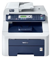
Brother MFC-9120CN
Рейтинг
Снят с производства
Тип устройства
МФУ
Технология печати
светодиодная
Макс. формат
A4
Число страниц в месяц
25000
Цветность печати
цветная
Общие характеристики |
|
---|---|
Число страниц в месяц |
25 000 |
Технология печати |
светодиодная |
Печать фотографий |
|
Размещение |
настольный |
Цветность печати |
цветная |
Телефон |
|
Макс. формат |
A4 |
Копир |
![]() |
Сканер |
![]() |
Факс |
![]() |
Тип устройства |
МФУ |
Тип |
лазерный/светодиодный |
Область применения |
малый офис |
Принтер |
|
Прямая печать |
|
Печать без полей |
|
Двусторонняя печать |
|
Пигментные чернила |
|
Количество цветов |
4 |
Макс, разрешение для ч/б печати |
|
По Y | 600 |
По X | 600 |
По X | 2 400 |
Время выхода первого отпечатка |
|
Ч/б | 15 |
Цветн, | 16 |
Копир |
|
Шаг масштабирования |
0,01 |
Макс, количество копий за цикл |
99 |
Значение масштаба |
|
Минимальное | 0,25 |
Максимальное | 4 |
Макс, разрешение (ч/б) |
|
По Y | 600 |
По X | 600 |
Скорость цветного копирования |
|
A4 | 16 |
Сканер |
|
Емкость устройства автоподачи оригиналов |
35 |
Тип сканера |
планшетный/протяжный |
Макс. формат оригинала |
A4 |
Устройство автоподачи оригиналов |
одностороннее |
Стандарт WIA |
![]() |
Отправка изображения по e-mail |
![]() |
Стандарт TWAIN |
![]() |
Глубина цвета |
48 бит |
Тип датчика сканера |
контактный (CIS) |
Оттенки серого |
256 |
Разрешение сканера |
|
По Х | 1 200 |
По Y | 2 400 |
По Y (улучшенное) | 19 200 |
По Х (улучшенное) | 19 200 |
Расходные материалы |
|
Ресурс цветного картриджа/тонера |
1 400 |
Ресурс фотобарабана |
15 000 |
Ресурс ч/б картриджа/тонера |
2 200 |
Количество картриджей |
4 |
Печать на: |
|
Рулоне |
|
Фотобумаге |
|
CD/DVD |
|
Матовой бумаге |
![]() |
Глянцевой бумаге |
![]() |
Конвертах |
![]() |
Этикетках |
![]() |
Пленках |
![]() |
Карточках |
![]() |
Факс |
|
Цветной |
![]() |
PC Fax |
![]() |
Макс, скорость передачи данных |
33,6 Кбит/с |
Память |
600 |
Телефон |
|
Проводная трубка |
|
Стандарт DECT |
|
Автоответчик |
|
АОН |
|
Caller ID |
|
Спикерфон |
|
Беспроводная трубка |
|
Языки управления |
|
PCL 6 |
![]() |
PostScript 3 |
![]() |
PostScript |
![]() |
PCL 5c |
|
PCL 5e |
|
PPDS |
|
PostScript 2 |
|
Лотки |
|
Емкость лотка ручной подачи |
1 |
Подача бумаги |
|
Стандартная | 251 |
Вывод бумаги |
|
Стандартный | 100 |
Финишер |
|
Брошюровщик |
|
Сортер |
|
Степлер |
|
Интерфейсы |
|
Веб-интерфейс |
![]() |
Ethernet (RJ-45) |
![]() |
USB |
![]() |
Версия USB |
2,0 |
Bluetooth |
|
Устройство для чтения карт памяти |
|
RS-232 |
|
Wi-Fi |
|
FireWire (IEEE 1394) |
|
Инфракрасный порт |
|
LPT |
|
Память/Процессор |
|
Процессор |
VR5500 |
Объем памяти |
64 |
Макс, объем памяти |
576 |
Частота процессора |
300 |
Дополнительная информация |
|
Экран |
|
Работа от аккумулятора |
|
Поддержка ОС |
|
Windows |
![]() |
Mac OS |
![]() |
DOS |
|
Потребляемая мощность |
|
При работе | 480 |
В режиме ожидания | 10 |
Уровень шума |
|
В режиме ожидания | 30 |
При работе | 53 |
Габариты |
|
Ширина |
491 |
Глубина |
428 |
Высота |
401 |
Вес |
28,5 |
Модули
PANEL
MAINTENANCE PARTS
DOCUMENT SCANNER
FRAME L & DRIVE UNIT
PCB
ENGINE FRAME UNIT
ADF
LED JOINT COVER
FRAME R UNIT
FRAME
PAPER FEEDER
COVERS
FUSER UNIT
PAPER CASSETTE
Детали COVERS
Деталь: | PANEL UNIT, MFC9010CN |
Парткод: | LS8110001 |
Деталь: | PANEL UNIT, MFC9120CN |
Парткод: | LS8097002 |
Деталь: | PANEL UNIT, MFC9320CW |
Парткод: | LS8097001 |
Деталь: | PANEL COVER ASSY, MFC9010CN FOR US/CAN |
Парткод: | LS8120001 |
Деталь: | PANEL COVER ASSY, MFC9120CN FOR US/CAN |
Парткод: | LS8114001 |
Деталь: | PANEL COVER ASSY, MFC9320CW FOR US/CAN |
Парткод: | LS8151001 |
Деталь: | PANEL COVER ASSY, MFC9120CN FOR GER/AUS |
Парткод: | LS8280001 |
Деталь: | PANEL COVER ASSY, MFC9320CW FOR GER/AUS |
Парткод: | LS8409001 |
Деталь: | PANEL COVER ASSY, MFC9120CN FOR UK/BEL/CHE/GUL |
Парткод: | LS8149001 |
Деталь: | PANEL COVER ASSY, MFC9320CW FOR UK/BEL/CHE |
Парткод: | LS8153001 |
Деталь: | PANEL COVER ASSY, MFC9120CN FOR FRA |
Парткод: | LS8293001 |
Деталь: | PANEL COVER ASSY, MFC9320CW FOR FRA |
Парткод: | LS8414001 |
Деталь: | PANEL COVER ASSY, MFC9120CN FOR NLD(DUTCH) |
Парткод: | LS8355001 |
Деталь: | PANEL COVER ASSY, MFC9320CW FOR NLD(DUTCH) |
Парткод: | LS8525001 |
Деталь: | PANEL COVER ASSY, MFC9120CN FOR SPA |
Парткод: | LS8299001 |
Деталь: | PANEL COVER ASSY, MFC9320CW FOR SPA |
Парткод: | LS8416001 |
Деталь: | PANEL COVER ASSY, MFC9120CN FOR ITA |
Парткод: | LS8303001 |
Деталь: | PANEL COVER ASSY, MFC9320CW FOR ITA |
Парткод: | LS8418001 |
Деталь: | PANEL COVER ASSY, MFC9120CN FOR POR |
Парткод: | LS8360001 |
Деталь: | PANEL COVER ASSY, MFC9320CW FOR POR |
Парткод: | LS8528001 |
Деталь: | PANEL COVER ASSY, MFC9120CN FOR SGP/ARL/NZ |
Парткод: | LS8368001 |
Деталь: | PANEL COVER ASSY, MFC9120CN FOR PND |
Парткод: | LS8375001 |
Деталь: | PANEL COVER ASSY, MFC9320CW FOR PND |
Парткод: | LS8539001 |
Деталь: | TAPTITE CUP B M3X10 |
Парткод: | 87311016 |
Деталь: | RUBBER KEY R, MFC9010CN |
Парткод: | LS8099003 |
Деталь: | RUBBER KEY R, MFC9120CN |
Парткод: | LS8099002 |
Деталь: | RUBBER KEY R, MFC9320CW |
Парткод: | LS8099001 |
Деталь: | RUBBER KEY L, MFC9010CN |
Парткод: | LS8112001 |
Деталь: | RUBBER KEY L, MFC9120CN |
Парткод: | LS8103002 |
Деталь: | RUBBER KEY L, MFC9320CW |
Парткод: | LS8103001 |
Деталь: | PANEL PCB ASSY, MFC9010CN |
Парткод: | LT0715003 |
Деталь: | PANEL PCB ASSY, MFC9120CN/MFC9320CW |
Парткод: | LT0715001 |
Деталь: | LCD |
Парткод: | A62009001 |
Деталь: | LCD COVER |
Парткод: | LS8108001 |
Деталь: | ADDRESS LABEL, MFC9120CN/MFC9320CW |
Парткод: | LS8119001 |
Деталь: | PAPER FEEDING KIT (SP) |
Парткод: | LU6068001 |
Деталь: | RUBBER FOOT |
Парткод: | LU5114001 |
Деталь: | PF REGISTRATION SOLENOID |
Парткод: | LU5084001 |
Деталь: | LM HOOKB |
Парткод: | LU6489001 |
Деталь: | LM HOOK C |
Парткод: | LU5094001 |
Деталь: | HOOK SPRING BC10 |
Парткод: | LR0910001 |
Деталь: | PICK-UP SOLENOID |
Парткод: | LU5102001 |
Деталь: | TAPTITE BIND B M3X10 |
Парткод: | LU5694001 |
Деталь: | PICK-UP SOLENOID LEVER SPRING |
Парткод: | LU2032001 |
Деталь: | PICK-UP SECTOR GEAR SPRING |
Парткод: | LU5104001 |
Деталь: | FRICTION SPRING |
Парткод: | LU5098001 |
Деталь: | DRUM DEVELOP DRIVE UNIT |
Парткод: | LU5115001 |
Деталь: | FUSER/EJECT DRIVE MOTOR |
Парткод: | LU5148001 |
Деталь: | TAPTITE CUP S M3X6 SR |
Парткод: | LU5691001 |
Деталь: | TAPTITE BIND B M4X12 |
Парткод: | LU5693001 |
Деталь: | FUSER/EJECT DRIVE MOTOR SENSOR PCB ASSY |
Парткод: | LV0140001 |
Деталь: | EJECT FRONT SENSOR PCB ASSY |
Парткод: | LV0136001 |
Деталь: | TONER/NEW SENSOR PCB ASSY |
Парткод: | LV0137001 |
Деталь: | PT SENSOR HOLDER |
Парткод: | UL9037001 |
Деталь: | DRUM MOTOR ORIGIN SENSOR PCB ASSY |
Парткод: | LT1028001 |
Деталь: | REGISTRATION MARK RELAY PCB ASSY |
Парткод: | LV0139001 |
Деталь: | DEVELOP DRIVE MOTOR |
Парткод: | LU5123001 |
Деталь: | PAPER FEED MOTOR ASSY |
Парткод: | LU5160001 |
Деталь: | SCREW BIND M3X4 |
Парткод: | 300416 |
Деталь: | BATTERY ASSY, MFC9120CN/ MFC9320CW |
Парткод: | LG6167001 |
Деталь: | MAIN PCB, MFC9010CN FOR US/ CAN |
Парткод: | LT0711001 |
Деталь: | MAIN PCB, MFC9010CN FOR US (*) |
Парткод: | LT0711051 |
Деталь: | MAIN PCB, MFC9010CN FOR CAN (*) |
Парткод: | LT0711052 |
Деталь: | MAIN PCB, MFC9120CN FOR US/ CAN |
Парткод: | LT0710001 |
Деталь: | MAIN PCB, MFC9120CN FOR US (*) |
Парткод: | LT0710051 |
Деталь: | MAIN PCB, MFC9120CN FOR CAN (*) |
Парткод: | LT0710052 |
Деталь: | MAIN PCB, MFC9320CW FOR US/ CAN |
Парткод: | LT0709001 |
Деталь: | MAIN PCB, MFC9320CW FOR US (*) |
Парткод: | LT0709051 |
Деталь: | MAIN PCB, MFC9320CW FOR CAN (*) |
Парткод: | LT0709052 |
Деталь: | MAIN PCB, MFC9120CN FOR GER/ UK/ FRA/ BEL/ NLD/ CHE/ AUS/ SPA/ ITA/ POR/ SGP/ GUL/ ARL/ NZ/ PND |
Парткод: | LT0710004 |
Деталь: | MAIN PCB, MFC9120CN FOR GER/ UK/ FRA/ BEL/ NLD/ CHE/ AUS/ SPA/ ITA/ POR/ PND (*) |
Парткод: | LT0710054 |
Деталь: | MAIN PCB, MFC9320CW FOR GER/ UK/ FRA/ BEL/ NLD/ CHE/ AUS/ SPA/ ITA/ POR/ PND |
Парткод: | LT0709004 |
Деталь: | MAIN PCB, MFC9320CW FOR GER/ UK/ FRA/ BEL/ NLD/ CHE/ AUS/ SPA/ ITA/ POR/ PND (*) |
Парткод: | LT0709054 |
Деталь: | ENGINE PCB ASSY |
Парткод: | LV0148001 |
Деталь: | NCU PCB ASSY, MFC9120CN/ MFC9320CW FOR US |
Парткод: | LG5925001 |
Деталь: | NCU PCB ASSY, MFC9120CN/ MFC9320CW FOR CAN |
Парткод: | LG5925003 |
Деталь: | NCU PCB ASSY, MFC9120CN/ MFC9320CW FOR GER/ AUS |
Парткод: | LG5923054 |
Деталь: | NCU PCB ASSY, MFC9120CN/ MFC9320CW FOR UK/ BEL/ NLD/ PND |
Парткод: | LG5923067 |
Деталь: | NCU PCB ASSY, MFC9120CN/ MFC9320CW FOR FRA/ SPA/ ITA/ POR |
Парткод: | LG5923065 |
Деталь: | NCU PCB ASSY, MFC9120CN/ MFC9320CW FOR CHE |
Парткод: | LG5923056 |
Деталь: | NCU PCB ASSY, MFC9120CN FOR SGP |
Парткод: | LG6190005 |
Деталь: | NCU PCB ASSY, MFC9120CN FOR GUL |
Парткод: | LG6872003 |
Деталь: | NCU PCB ASSY, MFC9120CN FOR ARL/ NZ |
Парткод: | LG6198003 |
Деталь: | LOW-VOLTAGE POWER SUPPLY PCB ASSY FOR US/ CAN |
Парткод: | LT0748001 |
Деталь: | LOW-VOLTAGE POWER SUPPLY PCB ASSY FOR GER/ UK/ FRA/ BEL/ NLD/ CHE/ AUS/ SPA/ ITA/ POR/ SGP/ GUL/ ARL/ NZ/ PND |
Парткод: | LT0749001 |
Деталь: | HIGH-VOLTAGE POWER SUPPLY PCB ASSY |
Парткод: | LV0146001 |
Деталь: | WASTE TONER SENSOR |
Парткод: | LM9221001 |
Деталь: | REGISTRATION SENSOR HOLDER ASSY |
Парткод: | LU5047001 |
Деталь: | REGISTRATION MARK R PCB ASSY |
Парткод: | LV0144001 |
Деталь: | TAPTITE BIND B M3X10 |
Парткод: | LU5694001 |
Деталь: | ADF UNIT(SP) |
Парткод: | LS8311001 |
Деталь: | HINGE ASSY L |
Парткод: | LS3329001 |
Деталь: | HINGE R |
Парткод: | LS8154001 |
Деталь: | HINGE R SUPPORT |
Парткод: | LS8155001 |
Деталь: | MFC EMBLEM, MFC9010CN/MFC9120CN |
Парткод: | LS8204001 |
Деталь: | MFC EMBLEM, MFC9320CW |
Парткод: | LS8203001 |
Деталь: | TAPTITE CUP B M3X10 |
Парткод: | 87311016 |
Деталь: | TAPTITE CUP S M3X12 |
Парткод: | 87321217 |
Деталь: | DOCUMENT COVER SUB ASSY |
Парткод: | LS8076001 |
Деталь: | DRIVE FRAME ASSY |
Парткод: | LS0536001 |
Деталь: | ADF SENSOR PCB ASSY |
Парткод: | LT0722001 |
Деталь: | EJECTION ROLLER ASSY |
Парткод: | LF6577001 |
Цена: | 1 700 ₽ |

Деталь: | LF ROLLER ASSY |
Парткод: | LF6579001 |
Цена: | 1 300 ₽ |
Деталь: | DOCUMENT HOLD ASSY |
Парткод: | LP2591001 |
Деталь: | DOCUMENT HOLD SPRING |
Парткод: | LP2594001 |
Деталь: | PAPER STACK LEVER |
Парткод: | LS8083001 |
Деталь: | UPPER DOCUMENT CHUTE ASSY |
Парткод: | LS8085001 |

Деталь: | SEPARATE ROLLER SHAFT ASSY |
Парткод: | LS8090001 |
Цена: | 2 100 ₽ |
Деталь: | GEAR COVER |
Парткод: | LS8094001 |
Деталь: | ADF COVER ASSY |
Парткод: | LS8095001 |
Деталь: | TAPTITE CUP S M3X6 SR |
Парткод: | LU5691001 |
Деталь: | HINGE BASE |
Парткод: | LS8141001 |
Деталь: | DOCUMENT STOPPER |
Парткод: | LS8078001 |
Деталь: | ADF MOTOR |
Парткод: | LF9081001 |
Деталь: | TAPTITE BIND S M3X6 |
Парткод: | 85320616 |
Деталь: | SEPARATION RUBBER ASSY |
Парткод: | LS0978001 |
Деталь: | LED ASSY (SP) |
Парткод: | LU5831001 |
Деталь: | Z SPRING L |
Парткод: | LU5253001 |
Деталь: | Z SPRING R |
Парткод: | LU6063001 |
Деталь: | HOLDER HOOK |
Парткод: | LU6238001 |
Деталь: | LED HEAD CONTROL PCB ASSY |
Парткод: | LV0441001 |
Деталь: | LED POWER RELAY PCB ASSY |
Парткод: | LT0886001 |
Деталь: | JOINT COVER SUB ASSY, MFC9010CN |
Парткод: | LS8009001 |
Деталь: | JOINT COVER SUB ASSY, MFC9120CN/MFC9320CW |
Парткод: | LS8147001 |
Деталь: | INNER CHUTE 2 ASSY |
Парткод: | LS8029001 |
Деталь: | TOP DRESS COVER L |
Парткод: | LS8041001 |
Деталь: | TOP DRESS COVER R |
Парткод: | LS8042001 |
Деталь: | PULL ARM L |
Парткод: | LS8062001 |
Деталь: | PULL ARM R |
Парткод: | LS8063001 |
Деталь: | PULL ARM GUIDE |
Парткод: | LS8064001 |
Деталь: | PULL ARM SPRING ADF L |
Парткод: | LS8136001 |
Деталь: | PULL ARM SPRING ADF R |
Парткод: | LS0895001 |
Деталь: | LOCK CLAW |
Парткод: | LF6148001 |
Деталь: | TAPTITE CUP S M3X6 SR |
Парткод: | LU5691001 |
Деталь: | TAPTITE BIND B M4X12 |
Парткод: | LU5693001 |
Деталь: | TC RELEASE LEVER |
Парткод: | LS8018001 |
Деталь: | PAPER STACK LEVER ASSY |
Парткод: | LU6067001 |
Деталь: | JOINT COVER LOCK LEVER |
Парткод: | LS8021001 |
Деталь: | JOINT COVER LOCK SPRING |
Парткод: | LS8022001 |
Деталь: | FB LOCK LEVER L |
Парткод: | LS8023001 |
Деталь: | FB LOCK LEVER R |
Парткод: | LS8024001 |
Деталь: | SIDE FRAME R |
Парткод: | LU5169001 |
Деталь: | TOP COVER OPEN SWITCH HARNESS ASSY |
Парткод: | LV0183001 |
Деталь: | TONER LED PCB ASSY |
Парткод: | LV0152001 |
Деталь: | LED HOLDER |
Парткод: | LU5170001 |
Деталь: | DEVELOP RELEASE SENSOR PCB ASSY |
Парткод: | LV0188001 |
Деталь: | TAPTITE CAP B 3X8 |
Парткод: | UU0552001 |
Деталь: | HVPS CONTROL PCB ASSY |
Парткод: | LV0149001 |
Деталь: | TAPTITE PAN (S/P W) B M3X10 |
Парткод: | Z07200001 |
Деталь: | RUBBER FOOT |
Парткод: | LU5114001 |
Деталь: | DEVELOP RELEASE MOTOR ASSY |
Парткод: | LU5181001 |
Деталь: | TAPTITE BIND S M3X5 |
Парткод: | 85320516 |
Деталь: | AIR FILTER HOLDER ASSY |
Парткод: | LU5190001 |
Деталь: | OZONE FILTER ASSY |
Парткод: | LU6122001 |
Деталь: | PAPER EJECT ACTUATOR |
Парткод: | LU5187001 |
Деталь: | PAPER EJECT ACTUATOR TOP |
Парткод: | LU5188001 |
Деталь: | PAPER EJECT ACTUATOR SPRING |
Парткод: | LU5189001 |
Деталь: | EJECT REAR SENSOR PCB ASSY |
Парткод: | LV0141001 |
Деталь: | LVPS COVER |
Парткод: | LS8056001 |
Деталь: | TAPTITE BIND B M4X12 |
Парткод: | LU5693001 |
Деталь: | LV FAN ASSY |
Парткод: | LU5200001 |
Деталь: | MAIN FAN ASSY |
Парткод: | LU5202001 |
Деталь: | ARM GUIDE L COVER |
Парткод: | LU5216001 |
Деталь: | TC ARM SPRING |
Парткод: | LS8003001 |
Деталь: | BELT DRIVE UNIT |
Парткод: | LU5227001 |
Деталь: | TAPTITE PAN(WASHER)B M4X12DA |
Парткод: | LU6109001 |
Деталь: | TR HEAD SPRING |
Парткод: | LU5172001 |
Деталь: | BELT CLEANER SPRING |
Парткод: | LU5177001 |
Деталь: | SPACER |
Парткод: | LU6330001 |
Деталь: | TOP COVER ARM R |
Парткод: | LS8132001 |
Деталь: | TOP COVER ARM L |
Парткод: | LS8131001 |
Деталь: | PAPER FEED UNIT |
Парткод: | LU5294001 |
Деталь: | TAPTITE CUP S M3X6 SR |
Парткод: | LU5691001 |
Деталь: | SHOULDER SCREW |
Парткод: | LM3856001 |
Деталь: | ROLLER HOLDER ASSY |
Парткод: | LU5311001 |
Деталь: | REGISTRATION FRONT/REAR SENSOR PCB ASSY |
Парткод: | LV0151001 |
Деталь: | MANUAL SENSOR PCB ASSY |
Парткод: | LV0150001 |
Деталь: | FRONT COVER |
Парткод: | LS8044001 |
Деталь: | FRONT COVER TOP, MFC9010CN/ MFC9120CN |
Парткод: | LS8158001 |
Деталь: | FRONT COVER TOP, MFC9320CW |
Парткод: | LS8215001 |
Деталь: | SPEAKER UNIT |
Парткод: | LT0727001 |
Деталь: | USB HOST RELAY PCB ASSY, MFC9320CW |
Парткод: | LV0261001 |
Деталь: | WIRELESS LAN PCB ASSY, MFC9320CW |
Парткод: | LT0963001 |
Деталь: | SIDE COVER R ASSY |
Парткод: | LS8138001 |
Деталь: | SIDE COVER L ASSY |
Парткод: | LS8139001 |
Деталь: | BACK COVER |
Парткод: | LU5426001 |
Деталь: | BACK COVER STOPPER L |
Парткод: | LU5427001 |
Деталь: | BACK COVER STOPPER R |
Парткод: | LU6131001 |
Деталь: | FUSER COVER ASSY |
Парткод: | LU5428001 |
Деталь: | MANUAL PAPER TRAY ASSY, MFC9010CN/ MFC9120CN |
Парткод: | LU5442001 |
Деталь: | MANUAL PAPER TRAY ASSY, MFC9320CW |
Парткод: | LU5442002 |
Деталь: | EXT CAP, MFC9120CN/ MFC9320CW FOR US/ CAN/ NLD/ CHE/ SPA/ POR/ SGP/ GUL/ ARL/ NZ/ PND |
Парткод: | LE8842001 |
Деталь: | MJ COVER EXT, MFC9120CN/ MFC9320CW FOR GER/ UK/ FRA/ BEL/ AUS/ ITA |
Парткод: | UF5745000 |
Деталь: | CORD HOOK, MFC9120CN/ MFC9320CW |
Парткод: | LS8214001 |
Деталь: | BROTHER EMBLEM, MFC9010CN/ MFC9120CN |
Парткод: | LU4163003 |
Деталь: | BROTHER EMBLEM, MFC9320CW |
Парткод: | LU4163001 |
Деталь: | LABEL REAR JAM |
Парткод: | LU5876001 |
Деталь: | LABEL FRONT JAM |
Парткод: | LU5877001 |
Деталь: | LABEL H/ SP CAUTION REAR |
Парткод: | LU5878001 |
Деталь: | LABEL HEAT CAUTION FOR US/ CAN |
Парткод: | LU5879001 |
Деталь: | LABEL HEAT CAUTION FOR GER/ UK/ FRA/ BEL/ NLD/ CHE/ AUS/ SPA/ ITA/ POR/ PND |
Парткод: | LU6173001 |
Деталь: | LABEL HEAT CAUTION FOR SGP/ GUL/ ARL/ NZ |
Парткод: | LU6335001 |
Деталь: | LABEL DR OPERATION |
Парткод: | LS8233001 |
Деталь: | LABEL DR OPERATION/ RIGHT |
Парткод: | LS8273001 |
Деталь: | LABEL SPRAY CAUTION |
Парткод: | LS8234001 |
Деталь: | HANDHOLD POSITION LABEL L |
Парткод: | LS8462001 |
Деталь: | HANDHOLD POSITION LABEL R |
Парткод: | LS8463001 |
Деталь: | TAPTITE BIND B M4X12 |
Парткод: | LU5693001 |
Деталь: | TAPTITE BIND B M3X8 |
Парткод: | 85310816 |
Деталь: | TAPTITE CUP B M3X8 |
Парткод: | 87310816 |
Деталь: | ACCESS COVER |
Парткод: | LS8052001 |
Деталь: | PAPER EJECT FRONT ACTUATOR |
Парткод: | LU5440001 |
Деталь: | FUSER UNIT 115V (SP) FOR US/ CAN |
Парткод: | LU5796001 |
Деталь: | FUSER UNIT 230V (SP) FOR GER/ UK/ FRA/ BEL/ NLD/ CHE/ AUS/ SPA/ ITA/ POR/ SGP/ GUL/ ARL/ NZ/ PND |
Парткод: | LU5797001 |
Деталь: | TAPTITE PAN B M4X14 |
Парткод: | LJ0395001 |
Деталь: | PAPER TRAY UNIT, MFC9010CN/ MFC9120CN |
Парткод: | LU5347001 |
Деталь: | PAPER TRAY UNIT, MFC9320CW |
Парткод: | LU5347002 |
Деталь: | COLOR LABEL FOR US/ CAN |
Парткод: | LU6035001 |
Деталь: | COLOR LABEL FOR GER/ UK/ FRA/ BEL/ NLD/ CHE/ AUS/ SPA/ ITA/ POR/ SGP/ GUL/ ARL/ NZ/ PND |
Парткод: | LU6036001 |

Деталь: | SEPARATION PAD ASSY |
Парткод: | LU5669001 |
Цена: | 1 200 ₽ |
Коды ошибок
13
14
15
16
17
18
1A
1B
1C
1D
20
21
22
23
24
25
26
28
29
2A
2C
2D
2E
2F
31
32
33
34
36
37
38
39
3A
3B
3E
40
42
43
44
45
46
47
48
49
4A
4B
4C
4D
4E
4F
52
54
56
58
59
5B
5C
5D
5E
5F
60
61
62
63
64
65
66
67
6A
6B
6C
6D
6F
70
73
74
75
76
78
7D
7F
80
81
82
83
84
87
88
8A
8D
8E
8F
91
94
96
97
9A
9D
9E
9F
A1
A2
A3
A4
A5
A6
A7
A8
AD
AF
B0
B1
B2
B7
B8
B9
BB
BD
C0
C1
C2
C3
C6
C7
C8
C9
CA
CB
CE
CF
D1
DE
E0
E1
E2
E3
E6
E9
EC
EF
F2
F4
F8
F9
FA
FB
FC
FD
FE
FF
Описание
Error code: | 13 |
Description: | Long tracks of missing print on several labels |
Causes: | Print element damaged. |
Remedy: | Replace the printhead. |
Error code: | 14 |
Description: | Wrinkled ribbon |
Causes: | Ribbon fed through the machine incorrectly. Incorrect burn temperature. Incorrect or uneven printhead pressure. Media not feeding properly; walking from side to side. The strip plate needs adjusting. The printhead needs vertical adjustment. The printhead is improperly balanced. The printhead and platen roller need to be realigned. |
Remedy: | See Load Ribbon on page 64. Set the darkness to the lowest possible setting for good print quality. See Adjust Print Darkness on page 78. Set the printhead pressure to the minimum needed for good print quality. See Adjust Printhead Pressure on page 70. Make sure that media is snug by adjusting the media guide, or call a service technician. Adjust the printhead balance. |
Error code: | 15 |
Description: | Printing too light or too dark over the entire label |
Causes: | The media or ribbon is not designed for high-speed operation. You are using an incorrect combination of media and ribbon for your application. You are using ribbon with direct thermal media. Incorrect or uneven printhead pressure. |
Remedy: | Replace supplies with those recommended for high-speed operation. 1. Switch to a different type of media or ribbon to try to find a compatible combination. 2. If necessary, consult your authorized Zebra reseller or distributor for information and advice. Direct thermal media does not require ribbon. To check if you are using direct thermal media, perform the label scratch test in When to Use Ribbon on page 62. Set the pressure to the minimum needed. See Adjust Printhead Pressure on page 70. |
Error code: | 16 |
Description: | Smudge marks on labels |
Causes: | The media or ribbon is not designed for high-speed operation. |
Remedy: | Replace supplies with those recommended for high-speed operation. |
Error code: | 17 |
Description: | Misregistration/skips labels |
Causes: | The printer is not calibrated. Improper label format. |
Remedy: | Recalibrate the printer. Use correct label format. |
Error code: | 18 |
Description: | Misregistration and misprint of one to three labels |
Causes: | The platen roller is dirty. Media does not meet specifications. |
Remedy: | See Clean the Printhead and Platen Roller on page 131. Use media that meets specifications. |
Error code: | 1A |
Description: | Disconnect |
Causes: | Transmission has not started (the phone line is too noisy). |
Remedy: | Check the quality of the phone line or restart the transmission at a later time. |
Error code: | 1B |
Description: | Document transmission fault |
Causes: | Document transmission error. |
Remedy: | Transmission: restart the transmission. Reception: ask your correspondent to retransmit the document. |
Error code: | 1C |
Description: | Magenta drum error. (An error occurred after the counter value exceeded the value more than twice as long as the life of the drum.) (Printing is not available until the drum unit is replaced.) |
Causes: | 1 Main PCB failure |
Remedy: | Replace the main PCB ASSY. |
Error code: | 1D |
Description: | Yellow drum error. (An error occurred after the counter value exceeded the value more than twice as long as the life of the drum.) (Printing is not available until the drum unit is replaced.) |
Causes: | 1 Main PCB failure |
Remedy: | Replace the main PCB ASSY. |
Error code: | 20 |
Description: | Vertical image or label drift |
Causes: | The printer is using non-continuous labels but is configured in continuous mode. The media sensor is positioned incorrectly. The media sensor is calibrated improperly. The platen roller is dirty. Improper printhead pressure settings (toggles). Improperly loaded ribbon or media. Incompatible media. |
Remedy: | Configure the printer for non-continuous and run calibration routine, if necessary. Ensure that the media sensor is properly positioned to read a single/consistent interlabel gap. See Calibrate Media and Ribbon Sensor Sensitivity on page 90. Clean the platen roller. See Clean the Printhead and Platen Roller on page 131. Adjust the printhead pressure to ensure proper functionality. Verify that the printer is loaded properly. Ensure that the interlabel gaps or notches are 2 to 4 mm and consistently placed. Media must not exceed minimum specifications for mode of operation. |
Error code: | 21 |
Description: | The bar code printed on a label does not scan. |
Causes: | The bar code is not within specifications because the print is too light or too dark. Not enough blank space around the bar code. |
Remedy: | Perform the FEED Self Test on page 120. Adjust the darkness or print speed settings as necessary. Leave at least 1/8 in. (3.2 mm) between the bar code and other printed areas on the label and between the bar code and the edge of the label. |
Error code: | 22 |
Description: | Loss of printing registration on labels. Excessive vertical drift in top-of-form registration. |
Causes: | The platen roller is dirty. Media guides are positioned improperly. The media type is set incorrectly. The media is loaded incorrectly. |
Remedy: | Clean the platen roller according to the instructions in Clean the Printhead and Platen Roller on page 131. Ensure that the media guides are properly positioned. Set the printer for the correct media type (gap/notch, continuous, or mark). See Set Media Type on page 81. Load media correctly. See Load Media on page 58. |
Error code: | 23 |
Description: | Auto Calibrate failed. |
Causes: | Media or ribbon is loaded incorrectly. The sensors could not detect the media or ribbon. The sensors are dirty or positioned improperly. The sensors are dirty, or media is positioned improperly for the sensors to detect. The media type is set incorrectly. |
Remedy: | Ensure that media and ribbon are loaded correctly. Manually calibrate the printer. See Calibrate Media and Ribbon Sensor Sensitivity on page 90. Ensure that the sensors are clean and that media is positioned properly. Set the printer for the correct media type (gap/notch, continuous, or mark). See Set Media Type on page 81. |
Error code: | 24 |
Description: | A label format was sent to the printer but was not recognized. The DATA light does not flash. |
Causes: | The communication parameters are incorrect. |
Remedy: | Check the printer driver or software communications settings (if applicable). If you are using serial communication, check the serial port setting in the control panel menu. See Set Serial Communications on page 91. If you are using serial communication, make sure you are using a null modem cable or a null modem adapter. Using the control panel controls, check the protocol setting. It should be set to NONE. See Set Protocol on page 93. If a driver is used, check the driver communication settings for your connection. |
Error code: | 25 |
Description: | A label format was sent to the printer. Several labels print, then the printer skips, misplaces, misses, or distorts the image on the label. |
Causes: | The serial communication settings are incorrect. |
Remedy: | Ensure that the flow control settings match. Check the communication cable length. See Table 5 on page 48 for requirements. Check the printer driver or software communications settings (if applicable). |
Error code: | 26 |
Description: | A label format was sent to the printer but was not recognized. The DATA light flashes but no printing occurs. |
Causes: | The prefix and delimiter characters set in the printer do not match the ones in the label format. Incorrect data is being sent to the printer. |
Remedy: | Verify the prefix and delimiter characters. See Set Format Prefix Character on page 94 and Set Delimiter Character on page 95 for the requirements. Check the communication settings on the computer. Ensure that they match the printer settings. If the problem continues, check the label format. |
Error code: | 28 |
Description: | The printer does not detect when the ribbon runs out. In thermal transfer mode, the printer did not detect the ribbon even though it is loaded correctly. |
Causes: | The ribbon-out threshold is set too high to detect the ribbon. On a sensor profile, the ribbon-out threshold (circled in Figure 15) appears above the black bars that indicate the ribbon. This happens if you calibrate the printer without ribbon and later insert ribbon without recalibrating the printer or loading printer defaults. |
Remedy: | 1. Print a sensor profile (see Print Sensor Profile on page 89), and note the location of the ribbon-out threshold (circled in Figure 15). 2. Calibrate the printer, this time using ribbon, or load printer defaults. See Calibrate Media and Ribbon Sensor Sensitivity on page 90 or LOAD DEFAULTS on page 73. Important • Loading defaults resets all printer parameters back to factory defaults. 3. Print another sensor profile, and compare it to the first one. 4. If the ribbon-out threshold is still too high, you may manually change the value. |
Error code: | 29 |
Description: | The ribbon light is on even though ribbon is loaded correctly. |
Causes: | The printer was not calibrated for the label and ribbon being used. |
Remedy: | Perform the calibration procedure in Calibrate Media and Ribbon Sensor Sensitivity on page 90. |
Error code: | 2A |
Display: | No Ink Cartridge |
Description: | Faulty NVRAM Data |
Causes: | NVRAM PWB-A (Engine Control Board) |
Remedy: | 1 Unplug the power cord and plug it in, then turn OFF and ON the Power Switch. 2 Check NVRAM (PJ26) on PWB-A for proper connection and correct as necessary. 3 Change PWB-A. |
Error code: | 2C |
Display: | No Ink Cartridge |
Description: | NVRAM Install Failure |
Causes: | NVRAM PWB-A (Engine Control Board) |
Remedy: | 1 Unplug the power cord and plug it in, then turn OFF and ON the Power Switch. 2 Check NVRAM (PJ26) on PWB-A for proper connection and correct as necessary. 3 Change PWB-A. |
Error code: | 2D |
Display: | No Ink Cartridge |
Description: | Scan drive problem or fuse 5 on optics board |
Causes: | 1 Toner/New sensor PCB failure. 2 Engine PCB failure. 3 High-voltage power supply PCB failure. 4 Main PCB failure |
Remedy: | <User Check> - Check if an incompatible Ink cartridge is loaded. - Reload the Ink cartridge. - Replace the Ink cartridge. 1 Ink cartridge detection sensor defective Replace the Ink refill ASSY. 2 Main PCB defective Replace the Main PCB ASSY. |
Error code: | 2E |
Display: | Unable to print 2E |
Description: | Unable to communicate with the Ink cartridge IC chip. (On the main unit side) |
Causes: | 1 Toner/New sensor PCB failure. 2 Engine PCB failure. 3 High-voltage power supply PCB failure. 4 Main PCB failure |
Remedy: | 1 Main PCB defective Replace the Main PCB ASSY. |
Error code: | 2F |
Display: | Close Ink Cover |
Description: | The Ink cartridge cover sensor detected an opened cover. |
Remedy: | <User Check> - Close the Ink cartridge cover. 1 Ink cartridge cover sensor harness connection failure Reconnect the Ink cartridge cover sensor harness. 2 Damaged Ink cartridge cover Replace the Ink cartridge cover. 3 Ink cartridge cover sensor defective Replace the Ink cartridge cover sensor ASSY. 4 Main PCB defective Replace the Main PCB ASSY. |
Error code: | 31 |
Description: | The LCD is missing characters or parts of characters |
Causes: | The LCD may need replacing. |
Remedy: | Run the Power-On Self Test on page 117 and check that the LCD display shows all characters. If not, replace the LCD. |
Error code: | 32 |
Description: | Changes in parameter settings did not take effect |
Causes: | Parameters are set incorrectly. A command turned off the ability to change the parameter. A command changed the parameter back to the previous setting. If the problem continues, there may be a problem with the main logic board. |
Remedy: | 1. Set parameters and save permanently. 2. Turn the printer off (O) and then on (I). Refer to the ZPL Programming Guide. Refer to the ZPL Programming Guide. Replace the main logic board. |
Error code: | 33 |
Description: | The printer fails to calibrate or detect the top of the label. |
Causes: | The printer was not calibrated for the label being used. The printer is configured for continuous media. The driver or software configuration is not set correctly. |
Remedy: | Perform the calibration procedure in Calibrate Media and Ribbon Sensor Sensitivity on page 90. Set the media type to noncontinuous media. See Set Media Type on page 81. Driver or software settings produce commands that can overwrite the printer configuration. Check the driver or software media-related setting. |
Error code: | 34 |
Description: | Non-continuous labels are being treated as continuous labels. |
Causes: | The printer was not calibrated for the media being used. The printer is configured for continuous media. |
Remedy: | Perform the calibration procedure in Calibrate Media and Ribbon Sensor Sensitivity on page 90. Set the media type to noncontinuous media. See Set Media Type on page 81. |
Error code: | 36 |
Description: | The printer locks up while running the Power-On Self Test. |
Causes: | Main logic board failure. |
Remedy: | Replace the main logic board. |
Error code: | 37 |
Description: | Non-continuous labels are being treated as continuous labels. |
Causes: | The printer is configured for continuous media. The printer was not calibrated for the media being used. |
Remedy: | Set the media type to noncontinuous media. See Set Media Type on page 56. Perform the calibration procedure in Calibrate Media and Ribbon Sensors on page 67. |
Error code: | 38 |
Description: | All lights are on, but nothing displays on the LCD, and the printer locks up. |
Causes: | Internal electronic or firmware failure. |
Remedy: | Turn the printer power Off (O) and then On (I). If the printer locks up again, replace the main logic board. |
Error code: | 39 |
Description: | The printer locks up while running the Power-On Self Test. |
Causes: | Main logic board failure. |
Remedy: | Replace the main logic board. |
Error code: | 3A |
Description: | Engine PCB transfer error. (Communication error between the main CPU and sub CPU.) |
Causes: | 1 Harness connection failure between engine PCB and main PCB. 2 Engine PCB failure. 3 Main PCB failure. |
Remedy: | 1 Harness connection failure between engine PCB and main PCB Check the harness connection between the engine PCB ASSY and main PCB ASSY, and reconnect it. 2 Engine PCB failure Replace the engine PCB ASSY. 3 Main PCB failure Replace the main PCB ASSY. |
Error code: | 3B |
Display: | Unable to print 3B |
Description: | Main PCB RAM failure |
Causes: | Main PCB failure |
Remedy: | Replace the main PCB ASSY. |
Error code: | 3E |
Display: | Unable to print 3E |
Description: | EEPROM bus error (Not applicable) |
Causes: | Main PCB failure |
Remedy: | Replace the main PCB ASSY. |
Error code: | 40 |
Display: | Scanner locked |
Description: | 10-348 ERROR 40 FUSER MAIN LAMP FAILURE Note If this failure reoccurs three times successively, an Engine NVRAM value is set preventing further printer use until the Clear Tech Rep Fault, Clear <10-348 & 10-350> is run. |
Causes: | 1. Deformed paper sensor actuator or faulty sensor. 2. SMPS PBA or Main PBA is defective 3. Faulty cables or connectors. |
Remedy: | Switch printer power OFF. Remove the Fuser Assembly. Warning Fuser may be very hot. Use extreme caution to prevent burns. Measure the resistance between the Fuser Assembly connector P600-4 and P600-6. Does the resistance measure between 20K and 100K ohms? Y↓N→ Replace the Fuser Assembly. Reinstall Fuser. Remove the Rear Cover, Rear Shield and the Rear Shield Bracket. Measure the resistance between P404A-1 and P404A-2 on the Engine Control Board. Does the resistance measure between 20K and 100K ohms? Y↓N→ Repair or replace the wiring harness between the Engine Control Board and the Fuser. Replace the Engine Control Board. |
Error code: | 42 |
Display: | Self Diagnostic Temperature |
Description: | 10-352 ERROR 42 FUSER STS (FRONT) WARM TIME FAILURE |
Causes: | 1. The ‘Open Cover’ microswitch may be stuck or faulty 2. The tab on the front cover may be damaged or broken 3. Check the connector and cables between Switch and main PBA. |
Remedy: | Measure the resistance between the Fuser Assembly connector P600-1 and P600-3. Does the resistance measure approximately 6 ohms for a 110 VAC Fuser or approximately 20 ohms for a 220 VAC Fuser? Y↓N→ Replace the Fuser Assembly. Measure the resistance between the Fuser Assembly connector P600-4 and P600-6. Does the resistance measure between 20K and 100K ohms? Y↓N→ Replace the Fuser Assembly. Reinstall Fuser. Remove the Rear Cover, Rear Shield and the Rear Shield Bracket. Measure the resistance between P404A-1 and P404A-2 on the Engine Control Board. Does the resistance measure between 20K and 100K ohms? Y↓N→ Repair or replace the wiring harness between the Engine Control Board and the Fuser. Reinstall the Fuser. Switch printer power ON. Does the Fuser get warm? Y↓N→ Replace the Chassis AC Power Assembly. Replace the Engine Control Board. |
Error code: | 43 |
Display: | Send Error (AUTH) |
Description: | 10-353 ERROR 43 FUSER SSR1 ON TIME FAILURE |
Causes: | 1. The ‘Open Cover’ microswitch may be stuck or faulty 2. Check the connector and cables between Switch and main PBA. |
Remedy: | Measure the resistance between the Fuser Assembly connector P600-1 and P600-3. Does the resistance measure approximately 6 ohms for a 110 VAC Fuser or approximately 20 ohms for a 220 VAC Fuser? Y↓N→ Replace the Fuser Assembly. Measure the resistance between the Fuser Assembly connector P600-4 and P600-6. Does the resistance measure between 20K and 100K ohms? Y↓N→ Replace the Fuser Assembly. Reinstall Fuser. Remove the Rear Cover, Rear Shield and the Rear Shield Bracket. Measure the resistance between P404A-1 and P404A-2 on the Engine Control Board. Does the resistance measure between 20K and 100K ohms? Y↓N→ Repair or replace the wiring harness between the Engine Control Board and the Fuser. Reinstall the Fuser. Switch printer power ON. Does the Fuser get warm? Y↓N→ Replace the Chassis AC Power Assembly. Replace the Engine Control Board. |
Error code: | 44 |
Display: | Send Error (DNS) |
Description: | Fuser Sub Lamp Overheat Failure, Code 44 The front thermistor has detected an overheat condition. Note If this failure reoccurs three times successively, an Engine NVRAM value is set preventing further printer use until the Clear Tech Rep Fault is performed. |
Causes: | • Fuser • Engine Control Board |
Remedy: | 1 1. Turn OFF power, remove the fuser assembly and allow it to cool down. 2. Measure the resistance between the Fuser connector P600-7 and P600-9. 3. Does the resistance measure between 30 K and 190 K Ohms? Go to step 2. Replace the fuser assembly. 2 1. Reinstall the fuser assembly. 2. Enter service diagnostics. 3. From the Sensor Tests run the Fuser Temperature test. 4. Is the temperature indicated approximately 165o C? Go to step 4. Go to step 3. 3 1. Turn OFF printer power. 2. Measure the resistance between J641-4 and J641-5 on the engine control board. 3. Does the resistance measure between 30 K and 190 K Ohms? Go to step 4. Repair or replace the wiring harness. 4 1. Turn printer power back ON. 2. Is there ~+3.4 VDC between J590-3 and ground? Check the AC wiring harness to the fuser. If the check is OK, replace the AC drive assembly. Replace the engine control board. |
Error code: | 45 |
Display: | Send Error (POP3) |
Description: | Fuser STS (Rear) Failure, Code 45 Rear Thermistor open error. The machine logic detected an open circuit in the rear thermistor. |
Causes: | • Fuser • Engine Control Board |
Remedy: | 1 1. Turn OFF power, remove the fuser assembly and allow it to cool down. 2. Measure the resistance between the Fuser connector P600-7 and P600-9. 3. Does the resistance measure between 30 K and 190 K Ohms? Go to step 2. Replace the fuser assembly. 2 1. Reinstall the fuser assembly. 2. Enter service diagnostics. 3. From the Sensor Tests run the Fuser Temperature test. 4. Is the temperature indicated approximately 165o C? Replace the engine control board. Go to step 3. 3 1. Turn printer power OFF. 2. Check for an open circuit or poor connection between J641-4 and J641-5. 3. Is the wiring harness OK? Replace the engine control board. Repair or replace the wiring harness. |
Error code: | 46 |
Display: | Send Error (SMTP) |
Description: | 10-354 ERROR 46 FUSER STS (REAR) WARM TIME FAILURE |
Causes: | 1. Check stability of 24V supply to LSU. |
Remedy: | Measure the resistance between the Fuser Assembly connector P600-1 and P600-3. Does the resistance measure approximately 6 ohms for a 110 VAC Fuser or approximately 20 ohms for a 220 VAC Fuser? Y↓N→ Replace the Fuser Assembly. Measure the resistance between the Fuser Assembly connector P600-7 and P600-9. Does the resistance measure between 20 ohms and 100 ohms? Y↓N→ Replace the Fuser Assembly. Reinstall Fuser. Remove the Rear Cover, Rear Shield and the Rear Shield Bracket. Measure the resistance between P404A-3 and P404A-4 on the Engine Control Board. Does the resistance measure between 20K ohms and 100K ohms? Y↓N→ Repair or replace the wiring harness between the Engine Control Board and the Fuser. Reinstall the Fuser. Switch printer power ON. Does the Fuser get warm? Y↓N→ Replace the Chassis AC Power Assembly. Replace the Engine Control Board. |
Error code: | 47 |
Display: | Send Error (Wrong Config) |
Description: | 10-356 ERROR 47 FUSER SSR2 ON TIME FAILURE |
Causes: | There is disconnection in the paper transfer bias supply circuit. (Dirty or deformed electrodes) |
Remedy: | Measure the resistance between the Fuser Assembly connector P600-1 and P600-3. Does the resistance measure approximately 6 ohms for a 110 VAC Fuser or approximately 20 ohms for a 220 VAC Fuser? Y↓N→ Replace the Fuser Assembly. Measure the resistance between the Fuser Assembly connector P600-7 and P600-9. Does the resistance measure between 20K and 100K ohms? Y↓N→ Replace the Fuser Assembly. Reinstall Fuser. Remove the Rear Cover, Rear Shield and the Rear Shield Bracket. Measure the resistance between P404A-3 and P404A-4 on the Engine Control Board. Does the resistance measure between 20K and 100K ohms? Y↓N→ Repair or replace the wiring harness between the Engine Control Board and the Fuser. Reinstall the Fuser. Switch printer power ON. Does the Fuser get warm? Y↓N→ Replace the Chassis AC Power Assembly. Replace the Engine Control Board. |
Error code: | 48 |
Display: | [Stop Pressed] |
Description: | Fan Failure, Code 48 The machine logic detected a failure of the Fuser fan, LVPS fan, or rear fan. |
Causes: | • Fuser Fan • LVPS Fan • Rear Fan |
Remedy: | 1 1. Enter service diagnostics and run the fan test. 2. Does the fuser fan rotate at a high speed? Go to step 4. Go to step 2. 2 1. Check for voltage at J222-4. 2. Does the voltage measure +24 VDC? Go to step 3. Check the wiring to the fuser fan, if the wiring is OK, replace the engine control board. 3 Does the front panel indicate the fans are ON? Replace the fan. Check the wiring to the fuser fan, if the wiring is OK, replace the engine control board. 4 Does the rear fan revolve at high speed? Go to step 7. Go to step 5. 5 1. Check for voltage at J552-1. 2. Does the voltage measure +24 VDC? Go to step 6. Check the wiring to the rear fan, if the wiring is OK replace the interface board. If the problem continues, replace the engine control board. 6 Does the front panel indicate the fans are ON? Replace the rear fan. Check the wiring tot he rear fan, if the wiring is OK, replace the engine control board. 7 Does the LVPS fan revolve at high speed? The fans are operating correctly. If the problem persists, replace the engine control board. Go to step 8. 8 1. Check for voltage at J214-4. 2. Is +24 VDC present? Go to step 9. Check the wiring to the LVPS fan, if the wiring is OK, replace the engine control board. 9 Does the front panel indicate the fans are ON? Replace the LVPS assembly. Check the wiring to the LVPS fan, if the wiring is OK, replace the engine control board. |
Error code: | 49 |
Display: | Tray 1 Paper Empty |
Description: | There is no paper in the tray 1. |
Causes: | Pressure roller thermistor, pressure roller lamp connector, MCU |
Remedy: | Load paper in the tray 1. |
Error code: | 4A |
Description: | Magenta drum unit is at the end of life. |
Causes: | 1 Main PCB failure |
Remedy: | Replace the main PCB ASSY. |
Error code: | 4B |
Description: | Cyan drum unit is at the end of life. |
Causes: | 1 Main PCB failure |
Remedy: | Replace the main PCB ASSY. |
Error code: | 4C |
Description: | The black drum unit will reach the end of life soon. |
Causes: | 1 Main PCB failure |
Remedy: | Replace the main PCB ASSY. |
Error code: | 4D |
Display: | MACHINE ERROR 4D |
Description: | Ink absorber full sensor harness detected to be not correctly inserted. |
Causes: | 1 Main PCB failure |
Remedy: | 1 Ink absorber full sensor harness connection failure Reconnect the ink absorber full sensor harness. 2 Ink absorber full sensor defective Replace ink absorber box. 3 Main PCB defective Replace the main PCB ASSY. |
Error code: | 4E |
Description: | The magenta drum unit will reach the end of life soon. |
Causes: | 1 Main PCB failure |
Remedy: | Replace the main PCB ASSY. |
Error code: | 4F |
Display: | Unable to print 4F |
Description: | Head voltage drops quickly. |
Remedy: | <User Check> - This may occur when the surrounding temperature is low. Increase the surrounding temperature before use. - Unplug the power cord from the outlet. Plug it again after several seconds and check if the problem has been resolved. 1 Head flat cable connection failure Reconnect the Head flat cable. 2 Carriage flat cable connection failure Reconnect the Carriage flat cable. 3 Carriage PCB defective Replace the Carriage PCB ASSY. 4 Head defective Replace the Head/carriage unit. 5 Power supply PCB defective Replace the Power supply PCB ASSY. 6 Main PCB defective Replace the Main PCB ASSY. |
Error code: | 52 |
Display: | Send Error (POP3) |
Description: | Fan Failure One of the two fans has failed resulting in a fatal error. |
Causes: | • Rear Fan, PL1.1.19 • Fuser Fan, PL5.3.31 |
Remedy: | 1 Check the fans for damage or debris: • Fuser Fan, PL1.1.19 • Rear Fan, PL5.3.31 Is either fan damaged? Replace the defective fan. Go to Step 3. 2 Replace the defective fan. Does the error persist? Go to Step 3 Complete 3 Test the fans. Run the Service Diagnostics fan tests to isolate the defective fan. Did one of the fans fail? Go to the troubleshooting procedure for the specific fan. If both fans pass, replace the Engine Control Board. |
Error code: | 54 |
Display: | Send Error (Wrong Config) |
Description: | 10-398 ERROR 54 FAN FAILURE |
Causes: | · Loose cable connection · Defective ozone fan · Defective IOD2 board · Defective MCTL board |
Remedy: | Enter Service Diagnostics Mode. Run the “Fuser Fan” test. Does the Fuser Fan operate? Y↓N→ Remove the Rear Cover, Rear Shield and the Rear Shield Bracket. Measure the voltage between P530-1 on the Engine Control Board and frame ground. Does the voltage measure +24 VDC? Y↓N→ Replace the Engine Control Interface Board. Measure the voltage between P530-4 on the Engine Control Board and frame ground. Does the voltage measure 0 VDC? Y↓N→ Replace the Engine Control Interface Board. Measure the voltage between P530-3 on the Engine Control Board and frame ground. Does the voltage measure +5 VDC? Y↓N→ Replace the Engine Control Board. If the problem persists, repair or replace the harness between Engine Control Board and the Fuser Fan. Replace the Fuser Fan Assembly. Remove the Rear Cover, Rear Shield and the Rear Shield Bracket. Measure the voltage between P530-5 on the Engine Control Board and frame ground. Does the voltage measure +24 VDC? Y↓N→ Replace the Engine Control Interface Board. Measure the voltage between P530-8 on the Engine Control Board and frame ground. Does the voltage measure 0 VDC? Y↓N→ Replace the Engine Control Interface Board. Measure the voltage between P530-7 on the Engine Control Board and frame ground. Does the voltage measure +5 VDC? Y↓N→ Replace the Engine Control Board. If the problem persists, repair or replace the harness between Engine Control Board and the +24 VDC LVPS Fan. Replace the +24 VDC LVPS Fan. |
Error code: | 56 |
Display: | Toner Empty |
Description: | The toner cartridge has run out. The machine stops printing. |
Causes: | Harness connection failure of back cover switch ASSY. Eject actuator failure. Eject sensor PCB ASSY failure. Main PCB failure |
Remedy: | Replace the toner cartridge with a new one. |
Error code: | 58 |
Display: | Tray 1 Paper Empty |
Description: | There is no paper in the tray 1. |
Causes: | Harness connection failure between fuser unit and eject sensor PCB. Fuser unit failure. LVPS PCB failure. Eject sensor PCB ASSY failure. Main PCB failure |
Remedy: | Load paper in the tray 1. |
Error code: | 59 |
Display: | Tray 2 Paper Empty |
Description: | There is no paper in the optional tray 2. |
Causes: | Harness connection failure between fuser unit and eject sensor PCB. Fuser unit failure. LVPS PCB failure. Eject sensor PCB ASSY failure. Main PCB failure |
Remedy: | Load paper in the optional tray 2. |
Error code: | 5B |
Display: | Unable to print 5B |
Description: | New toner detection lever malfunction |
Causes: | New toner detection switch harness connection failure. New toner detection switch failure. Main PCB failure |
Remedy: | 1 New toner detection switch harness connection failure Check the harness connection of the new toner detection switch. Then, reconnect it. 2 New toner detection switch failure Replace the new toner harness ASSY. 3 Main PCB failure Replace the main PCB ASSY. |
Error code: | 5C |
Description: | It was detected that the size of the paper was less than the specified value. |
Causes: | 1 Engine PCB failure. 2 Main PCB failure. |
Remedy: | 1 Engine PCB failure Replace the engine PCB ASSY. 2 Main PCB failure Replace the main PCB ASSY. |
Error code: | 5D |
Display: | Unable to print 5D |
Description: | Overcurrent protection was activated in the driver IC during Purge cam operation. |
Causes: | The driving current has exceeded the limit due to an abnormal load applied to the maintenance unit. |
Remedy: | 1 Foreign materials in the Maintenance unit part Remove foreign materials. 2 Maintenance unit defective Replace the Maintenance unit. 3 Main PCB defective Replace the Main PCB ASSY. |
Error code: | 5E |
Display: | Unable to print 5E |
Description: | Overcurrent protection was activated in the driver IC during Maintenance unit pump operation. |
Causes: | The driving current has exceeded the limit due to an abnormal load applied to the maintenance unit. |
Remedy: | 1 Foreign materials in the Maintenance unit part Remove foreign materials. 2 Maintenance unit defective Replace the Maintenance unit. 3 Main PCB defective Replace the Main PCB ASSY. |
Error code: | 5F |
Description: | The waste toner box near full. (The sensor detected that thewaste toner became near full.) |
Causes: | 1 Harness connection failure of waste toner sensor. 2 Waste toner sensor failure. 3 High-voltage power supply PCB failure. 4 Main PCB failure. |
Remedy: | 1 Harness connection failure of waste toner sensor Check the harness connection of the waste toner sensor and reconnect it. 2 Waste toner sensor failure Check the sensor performance following the procedure described in “Function code 32”. If any problem occurs, replace the waste toner sensor. 3 High-voltage power supply PCB failure Replace the high-voltage power supply PCB ASSY. 4 Main PCB failure Replace the main PCB ASSY. |
Error code: | 60 |
Display: | Nongenuine Toner |
Description: | Imaging Unit Motor Failure, Code 60 |
Causes: | • Imaging Unit Drive Motor • Engine Control Board |
Remedy: | 1 1. Enter service diagnostics and run the Imaging Unit Motor test. 2. Does the motor operate correctly? Go to step 7. Go to step 2. 2 1. Is the voltage at J210-5 +5 VDC? Go to step 3. Replace the engine control board. 3 1. Is the voltage at J210-7 +24 VDC? Go to step 4. Use the +24 VDC wirenets to troubleshoot and resolve the missing voltage. 4 1. Enter service diagnostics. 2. While running the Imaging Unit Motor test, check the voltage at J210-1 and J210-2. 3. Is the voltage 0 VDC while the test is running? Go to step 5. Replace the engine control board. 5 Is the frequency between J210-4 and ground between 1 KHz and 1.3 KHz? Replace the imaging unit drive motor. Go to step 6. 6 1. Check for a short to ground at J210-4. 2. Is the wire grounded? Repair or replace the wiring harness. Replace the engine control board. 7 1. Enter service diagnostics. 2. While running the Imaging Unit Motor test, check the voltage at J210-9. 3. Is the voltage +5 VDC while the test is running? Replace the imaging unit drive motor. Replace the engine control board. |
Error code: | 61 |
Display: | Nongenuine Toner Replace Toner 1 |
Description: | The toner cartridge installed is not a genuine cartridge. |
Causes: | The printer warms up when the printer is turned on or the cover is closed, or wake from sleep mode. |
Remedy: | This message appears when you selected stop at the Non Genuine Toner prompt. Install the genuine toner cartridge. |
Error code: | 62 |
Display: | Nongenuine Toner Replace Toner |
Description: | The toner cartridge installed is not a genuine cartridge. |
Causes: | · Loose cable connection · Defective development clutch for magenta · Defective IOD2 board · Defective MCTL board |
Remedy: | This message appears when you selected stop at the Non Genuine Toner prompt. Install the genuine toner cartridge. |
Error code: | 63 |
Display: | Toner Exhausted |
Description: | HOST_IF_NO_DRIVER:PCI |
Causes: | Harness connection failure of new toner sensor harness ASSY. Harness connection failure of toner sensor PCB unit ASSY. New toner sensor harness ASSY failure (Toner empty). Toner sensor PCB unit ASSY failure. Main PCB failure. |
Remedy: | You can select either stop or continue. It you do not select any, the printer will as stop is selected. If you select stop, you cannot print untill the genuine cartridge is installed. If you select continue, you can keep printing but the guality cannot be guaranteed, and the product svpport is no longer provided. If you wunt to change the selection, turn the printer off and on to gave this message apper again, and then re-select stop or continue. |
Error code: | 64 |
Display: | Toner Exhausted Replace Toner 1 |
Description: | Cover Open |
Causes: | The Printer Cover is open or Toner Cartridge not installed. |
Error code: | 65 |
Display: | Toner Exhausted Replace Toner |
Description: | The life span of the toner cartridge is reached. |
Causes: | · Loose cable connection · Defective development solenoid – replace the front cover unit · Defective IOD2 board · Defective MCTL board |
Remedy: | This message appears when you selected continue at the Toner Exhausted prompt. Install the genuine toner cartridge. |
Error code: | 66 |
Display: | TONER SUPPLY LACK |
Description: | Orange light on The toner supplying error has occurred. |
Causes: | · Loose cable connection · Defective development solenoid – replace the front cover unit · Defective IOD2 board · Defective MCTL board |
Remedy: | 1) Check the sealing tape whether it is removed from the toner cartridge and the drum cartridge. (If it is not removed, clean the inside of the set and remove the tape, and then mount it.) 2) Check the harness connected between the Engine controller and the toner motor. (If the harness is out, insert it to the connector.) 3) Check the harness connected between the Engine controller and the toner ID board. (IF the harness is out, insert it to the connector.) 4) Check the harness connected between the Engine controller and the DEVE board. (If the harness is out, insert it to the connector.) 5) In the Engine diagnostic mode, operate the toner motor to check if the motor is operating. (If it is not operating, replace the toner motor.) 6) Check the sensor of the toner empty board whether it is dirty and there are foreign objects. (If it is dirty or there is a foreign object, remove it.) 7) Replace the toner container. 8) Replace the drum cartridge. |
Error code: | 67 |
Display: | TOP BIN FULL |
Description: | Orange light on The top bin is full of papers. Remove papers from the top bin. |
Causes: | Toner sensor PCB ASSY failure. Main PCB failure |
Remedy: | 1) Check the harness connected between the Engine controller and the exit board. (If the harness is out, insert it to the connector.) 2) In the Engine diagnostic mode, operate the full_R sensor to check if the sensor is operating. (If it is not operating, replace the exit board.) 3) Check the damage or warping of the sensor actuator. (If it is damaged or warped, replace the top bin full sensor.) 4) Replace the Engine controller. |
Error code: | 6A |
Description: | Fuser unit failure (The side thermistor does not detect 60°C within the specified time.) |
Causes: | Fuser unit harness connection failure. Fuser unit failure. LVPS PCB unit failure. Main PCB failure. |
Remedy: | 1 Fuser unit harness connection failure Check the harness connection of the fuser unit and reconnect it. 2 Fuser unit failure Replace the fuser unit. 3 LVPS PCB unit failure Replace the LVPS PCB unit. 4 Main PCB failure Replace the main PCB ASSY. |
Error code: | 6B |
Description: | Fuser unit failure (The center thermistor does not detect 100°C within the specified time.) |
Causes: | Fuser unit harness connection failure. Fuser unit failure. LVPS PCB unit failure. Main PCB failure. |
Remedy: | 1 Fuser unit harness connection failure Check the harness connection of the fuser unit and reconnect it. 2 Fuser unit failure Replace the fuser unit. 3 LVPS PCB unit failure Replace the LVPS PCB unit. 4 Main PCB failure Replace the main PCB ASSY. |
Error code: | 6C |
Display: | Unable to Print 6C |
Description: | Fuser unit failure (The center thermistor detects higher temperature than the specified value.) |
Causes: | Fuser unit harness connection failure. Fuser unit failure. LVPS PCB unit failure. Main PCB failure. |
Remedy: | 1 Fuser unit harness connection failure Check the harness connection of the fuser unit and reconnect it. 2 Fuser unit failure Replace the fuser unit. 3 LVPS PCB unit failure Replace the LVPS PCB unit. 4 Main PCB failure Replace the main PCB ASSY. |
Error code: | 6D |
Description: | Fuser unit failure (The center thermistor detects lower temperature than the specified value.) |
Causes: | Fuser unit harness connection failure. Fuser unit failure. LVPS PCB unit failure. Main PCB failure. |
Remedy: | 1 Fuser unit harness connection failure Check the harness connection of the fuser unit and reconnect it. 2 Fuser unit failure Replace the fuser unit. 3 LVPS PCB unit failure Replace the LVPS PCB unit. 4 Main PCB failure Replace the main PCB ASSY. |
Error code: | 6F |
Display: | Unable to Print 6F |
Description: | Fuser unit failure (The center and side thermistors detect extremely high temperature.) |
Causes: | Fuser unit harness connection failure. Fuser unit failure. LVPS PCB unit failure. Main PCB failure. |
Remedy: | 1 Fuser unit harness connection failure Check the harness connection of the fuser unit and reconnect it. 2 Fuser unit failure Replace the fuser unit. 3 LVPS PCB unit failure Replace the LVPS PCB unit. 4 Main PCB failure Replace the main PCB ASSY. |
Error code: | 70 |
Display: | No Paper |
Description: | No Paper |
Causes: | No paper in the paper cassette. |
Error code: | 73 |
Display: | Paper Jam 2 |
Description: | Paper Jam 2 |
Causes: | The front part of paper is jammed just after passing through the discharge sensor. |
Error code: | 74 |
Display: | [TRAY x] [PAPER SIZE] EMPTY |
Description: | F/W Overrun detect |
Causes: | · Loose cable connection · Defective cleaner clutch · Defective IOD2 board · Defective IOD1 board · Defective MCTL board |
Remedy: | 1) Check the harness connected between the Engine controller and the TA board. (If the harness is out, insert it to the connector.) 2) Check the harness connected between the TA board and the Pickup unit. (If the harness is out, insert it to the connector.) 3) Check the harness connected between the Pickup unit and the cassette sensing board. (If the harness is out, insert it to the connector.) 4) Check the pickup unit. (If it is inferior part or warped part, replace it.) 5) Check the damage of the cassette sensing B . (If it is damaged, replace the cassette sensing board.) 6) In the Engine diagnostic mode, operate the running count of the paper if it is under 39. (If it is over 39, replace the Pickup unit.) 7) Replace the TA board. |
Error code: | 75 |
Display: | [TRAY x] NOT INSTALLED |
Description: | VIC Limutter |
Causes: | · Loose cable connection · Defective fusing unit clutch · Defective IOD2 board · Defective MCTL board |
Remedy: | 1) Check for any warping or damage to the cassette (In the case of warping or damage, replace the cassette) |
Error code: | 76 |
Display: | Out Bin Full |
Description: | Fuser Firmware Failure A failure was detected in the Fuser Firmware. |
Causes: | • Fuser, PL5.1.1 • FSR/ADC Harness, PL5.2.28 • Engine Control Board, PL9.1.16 |
Remedy: | 1 Check the Fuser for damage. Is the Fuser damaged? Replace the Fuser. Go to Step 2. 2 Check the Fuser connection for damage. Any broken or bent pins? Repair or replace the parts. Go to Step 3. 3 Replace the Fuser. Does the error persist? Go to Step 4. Complete 4 Check all pins on the FSR/ADC Harness PL5.2.28 for continuity. 1. Disconnect P/J36 and P/J361. 2. Check continuity between J36 <=> J361. Replace the Engine Control Board. Replace the FSR/ ADC Harness. |
Error code: | 78 |
Display: | WRONG PAPER SIZE [PAPER] IN [TRAY x] |
Description: | Waste Cartridge Full Detection Sensor Failure, Code 78 |
Causes: | • Waste Cartridge • Waste Cartridge Full Sensor • Engine Control Board |
Remedy: | 1 1. Remove the waste cartridge sensor holder without disconnecting the harnesses. 2. Measure the voltage between the yellow wire on the waste cartridge full sensor and frame ground, alternately interrupting the sensor. 3. Does the voltage toggle between +5 and 0 VDC? Go to step 5. Go to step 2. 2 1. Measure the voltage between the gray wire and frame ground. 2. Does the voltage measure +5 VDC? Go to step 4. Go to step 3. 3 1. Remove the rear cover and rear shield. 2. Measure the voltage at J407B-17 on the engine control board. 3. Does the voltage measure +5 VDC? Inspect the wiring harness for damage and replace, if necessary. Replace the engine control board. 4 1. Measure the voltage between the violet wire and frame ground. 2. Does the voltage measure 0 VDC? Replace the waste cartridge full sensor. Inspect the wiring harness for damage and replace, if necessary. 5 1. Remove the rear cover and rear shield. 2. Measure the voltage at J407B-16 on the engine control board. 3. Alternately interrupt the sensor 4. Does the voltage toggle between +5 and 0 VDC? Replace the engine control board. Inspect the wiring harness for damage and replace, if necessary. |
Error code: | 7D |
Display: | Unable to clean 7D |
Description: | Dirt on drum unit |
Causes: | Dirt or dust on drum unit electrodes. HVPS PCB failure. Main PCB failure. |
Remedy: | 1 Dirt or dust on drum unit electrodes Clean the electrodes on the drum unit. ( p.271 "Electrodes location on the drum unit") 2 HVPS PCB failure Replace the HVPS PCB ASSY. 3 Main PCB failure Replace the main PCB ASSY. |
Error code: | 7F |
Description: | Fax paper setting mismatch (The setting paper becomes besides the A4/Letter/Legal/Folio.) |
Causes: | Main PCB failure |
Remedy: | 1 Main PCB failure Replace the main PCB ASSY. |
Error code: | 80 |
Display: | ERROR 80 FORMAT |
Description: | Engine Logic Board Failure, Code 80 |
Remedy: | 1. Cycle power to the printer to clear the error. 2. Did this clear the error? Complete Replace the engine control board or the image processor board. |
Error code: | 81 |
Display: | 81 |
Description: | Controller to Engine Communications Failure, Code 81 |
Remedy: | 1. Cycle power to the printer to clear the error. 2. Turn the printer off. 3. Remove the Image processor board, IP board cover and metal cover. 4. Inspect the orange ribbon cable between the relay board and the engine control board. 5. Is the connector fully seated and free from damage? Replace in the following order: • Image processor board • Electrical chassis assembly • Engine control board |
Error code: | 82 |
Display: | h`******** |
Description: | Engine Logic Board RAM/ROM Failure, Code 82 |
Remedy: | 1. Cycle power to the printer to clear the error. 2. Did this clear the error? Complete. Replace the engine control board. |
Error code: | 83 |
Display: | h`******** |
Description: | Engine Logic Board NVRAM Failure, Code 83 |
Remedy: | 1. Cycle power to the printer to clear the error. 2. Did this clear the error? Complete. Replace in the following order: • engine control board • image processor board |
Error code: | 84 |
Display: | h`******** |
Description: | Controller to Engine Logic Board Time Failure, Code 84 |
Remedy: | 1. Cycle power to the printer to clear the error. 2. Did this clear the error? Complete. Replace the engine control board. |
Error code: | 87 |
Display: | Paper Jam |
Description: | Tray Lift Failure, Code 87 The tray level sensor does not detect that the tray has lifted. Examine the trays and paper feed assemblies for any physical damage before starting the troubleshooting procedure. |
Causes: | • Tray Level Sensor • Paper Select Switch Assembly • Paper Feed Motor • Engine Control Board |
Remedy: | 1 Is the problem with Tray 2? Go to step 2. Go to step 7. 2 1. Pull out and then reseat Tray 2. 2. Does the lift motor operate? Go to step 3. Go to step 4. 3 1. Did the Error Code 87 clear from the front panel? Complete. This could be an intermittent problem. If the problem returns, replace in order: • tray level sensor • engine interface board Replace the engine control board. 4 1. Using Service Diagnostics test the tray 2 Sensors. 2. Does the level indicate H? Replace in order until resolved: • tray level sensor • No paper sensor • engine interface board • engine control board Go to step 5. 5 1. While still in diagnostics, pull out tray 2. 2. Does SW1-4: indicate LLLL? Replace in order until resolved: • paper-select switch assembly • engine interface board • engine control board Go to step 6 6 1. Reseat the paper tray. 2. Does SW1-4: indicate H in any position? Replace the paper feed motor. Replace in order until resolved: • paper-select switch assembly • engine interface board • engine control board 7 1. Pull out and then reseat the problem tray. 2. Listen for the motor, does the lift motor operate? Go to step 8. Go to step 9. 8 1. Did the Error Code 87 clear from the front panel? Complete. This could be an intermittent problem. If the problem returns, replace in order: • tray level sensor • engine interface board Replace the engine control board. 9 1. Using service diagnostics check the level sensor and no paper sensor. 2. Does the level indicate H? Replace in order until resolved: • tray level sensor • no paper sensor • LTA or HCF control board • engine interface board • engine control board Go to step 10. 10 1. While still in diagnostics, pull out tray 2. 2. Does SW(3,4,5)-4: indicate LLLL? Replace in order until resolved: • paper-select switch assembly • engine interface board • engine control board Go to step 11. 11 1. Reseat the paper tray. 2. Does SW(3,4,5,)-4: indicate H in any position? Replace the paper feed motor. Replace in order until resolved: • paper-select switch assembly • engine interface board • engine control board. |
Error code: | 88 |
Display: | Paper Jam |
Description: | Lower Tray Communication Failure, Code 88 |
Causes: | • Engine Control Interface Board • Tray module board • Engine Control board |
Remedy: | 1 Is J668-1 on the tray module board +5 VDC? Go to step 2. Use the wirenets to troubleshoot and repair the open wire. 2 Is J668-3 on the tray module board +24 VDC? Go to step 3. Use the wirenets to troubleshoot and repair the open wire. 3 1. Check the following connectors for continuity: • P669-1 to J534A-15 • P669-2 to J534A-14 • P669-3 to J534A-13 • P669-4 to J534A-12 • P669-5 to J534A-11 • P669-6 to J534A-10 2. Do all checks indicate continuity? Replace in the following order: • engine control interface board • tray module board • engine control board Check and repair broken wires or bad connectors. |
Error code: | 8A |
Display: | Paper Jam |
Description: | Paper jam in Tray 1 (T1) (It is detects by the registration front sensor) |
Causes: | Harness connection failure of registration front sensor PCB ASSY. Paper feed roller worn out. Registration front sensor PCB failure. Main PCB failure. |
Remedy: | 1 Harness connection failure of registration front sensor PCB ASSY Check the harness connection of the registration front sensor PCB ASSY in the appropriate tray, and reconnect it. 2 Paper feed roller worn out Replace the paper feed roller. 3 Registration front sensor PCB failure Check the sensor performance following the procedure ( p.183 "Operational Check of Sensors (Function code 32)"). If any problem occurs, replace the registration front sensor PCB ASSY. 4 Main PCB failure Replace the main PCB ASSY. |
Error code: | 8D |
Description: | Paper jam near paper eject tray (When power on, it is detects by the eject sensor.) |
Causes: | Paper eject actuator not operating smoothly catching in some position. Eject sensor PCB ASSY failure. Main PCB failure. |
Remedy: | 1 Paper eject actuator not operating smoothly catching in some position. Re-assemble the paper eject actuator. Ensure the paper eject sensor operates smoothly. 2 Eject sensor PCB ASSY failure Replace the eject sensor PCB ASSY. 3 Main PCB failure Replace the main PCB ASSY. |
Error code: | 8E |
Description: | Error in the adjustment of inter-color position alignment result when implementing it. |
Causes: | 1 Harness connection failure of the registration mark L PCB ASSY or registration mark R PCB ASSY. 2 Registration mark sensor holder ASSY failure. 3 Main PCB failure. |
Remedy: | 1 Harness connection failure of the registration mark L PCB ASSY or registration mark R PCB ASSY Check the harness connection of the registration mark sensor holder ASSY and reconnect it. 2 Registration mark sensor holder ASSY failure Replace the registration mark sensor holder ASSY. 3 Main PCB failure Replace the main PCB ASSY. |
Error code: | 8F |
Display: | Unable to print 8F |
Description: | Paper feed motor does not stop. The PF encoder sensor cannot detect the rotation of the Paper feed motor. |
Remedy: | <User Check> - Release the release lever at the back of the Paper tray and remove the jammed recording paper in Jam clear cover part, Platen part and front part. 1 Foreign materials in the recording paper feeding path Remove foreign materials. 2 Paper feed motor harness connection failure Reconnect the Paper feed motor harness. 3 PF encoder sensor harness connection defective Reconnect the PF encoder sensor harness. 4 PF encoder disk defective Replace the PF encoder disk. 5 PF encoder sensor defective Replace the PF encoder sensor PCB ASSY. 6 Paper feed motor defective Replace the Paper feed motor. 7 Main PCB defective Replace the Main PCB ASSY. |
Error code: | 91 |
Display: | 91 |
Description: | Total counter |
Remedy: | Wrong size paper loaded in the paper tray. Load the correct size of paper. Registration sensor defective Replace the registration sensor PCB. Main PCB defective Replace the main PCB. |
Error code: | 94 |
Description: | Non-Phaser 6300/6350 Fuser A CRUM-ID error indicates that a non-Phaser 6300 Fuser is installed. |
Causes: | • Fuser, PL5.1.1 • FSR/ADC Harness, PL5.2.28 • Engine Control Board, PL9.1.16 |
Remedy: | 1 Check the Fuser part number. Is the Fuser a genuine Xerox part. Go to Step 2. Replace the Fuser. 2 Check the Fuser for damage. Is the Fuser damaged? Replace the Fuser. Go to Step 3. 3 Check Fuser installation. Remove and reinstall the Fuser. Does the error persist? Go to Step 4 Complete 4 Replace the Fuser. Does the error persist? Go to Step 5. Complete 5 Check all pins on the FSR/ADC Harness PL5.2.28 for continuity. 1. Disconnect P/J36 and P/J361. 2. Check continuity between J36<=>J361. Replace the Engine Control Board. Replace the FSR/ ADC Harness. |
Error code: | 96 |
Description: | Document feeder drive problem |
Causes: | 1 Main PCB failure |
Remedy: | Replace the main PCB ASSY. |
Error code: | 97 |
Description: | Incorrect mode selected |
Causes: | 1 Main PCB failure |
Remedy: | Replace the main PCB ASSY. |
Error code: | 9A |
Description: | No paper is loaded in the MP tray (MP paper empty sensor fails to be turned ON.) |
Causes: | 1 Main PCB failure |
Remedy: | Replace the main PCB ASSY. |
Error code: | 9D |
Description: | Detection of incorrect registration sensor measurement value when implementing adjustment of inter-color position alignment. |
Causes: | 1 Foreign object is affixed around the density sensor. 2 Harness connection failure of registration mark sensor holder ASSY. 3 Registration mark sensor PCB failure. 4 High-voltage power supply PCB failure. 5 Engine PCB failure. 6 Low-voltage power supply PCB failure. 7 Main PCB failure. |
Remedy: | 1 Foreign object is affixed around the density sensor Remove the foreign object affixed around the density sensor. 2 Harness connection failure of registration mark sensor holder ASSY Check the harness connection of the registration mark sensor holder ASSY and reconnect it. 3 Registration mark sensor PCB failure Replace the registration mark sensor holder ASSY. 4 High-voltage power supply PCB failure Replace the high-voltage power supply PCB ASSY. 5 Engine PCB failure Replace the engine PCB ASSY. 6 Low-voltage power supply PCB failure Replace the low-voltage power supply PCB ASSY. 7 Main PCB failure Replace the main PCB ASSY. |
Error code: | 9E |
Description: | Toner of the color which is being used reaches the end of life when implementing adjustment of inter-color position alignment. |
Causes: | 1 Toner/New sensor PCB failure (Toner empty). 2 Engine PCB failure |
Remedy: | 1 Toner/New sensor PCB failure (Toner empty) Check the sensor performance following the procedure described in “Function code 32”. If any problem occurs, replace the Toner/New sensor PCB ASSY. 2 Engine PCB failure Replace the engine PCB ASSY. |
Error code: | 9F |
Display: | Paper Jam |
Description: | Paper empty (It is detects by the registration front sensor) |
Causes: | Registration front actuator catching in some position. Registration front sensor PCB harness connection failure. Registration front sensor PCB failure. Main PCB failure. |
Remedy: | 1 Registration front actuator catching in some position Re-assemble the registration front actuator. 2 Registration front sensor PCB harness connection failure Check the harness connection of the registration front sensor PCB and reconnect it. 3 Registration front sensor PCB failure Replace the registration front sensor PCB. 4 Main PCB failure Replace the main PCB ASSY. |
Error code: | A1 |
Display: | Cover is Open |
Description: | Jam at Door A |
Causes: | • Tray 1 (MPT) Feed Roller, PL10.1.53 • Tray 1 (MPT) Pick Roller, PL10.1.43 • Tray 1 (MPT) Retard Roller, PL10.1.16 • Registration Clutch #1, PL8.1.85 • Tray 2 Registration Motor, PL4.2.36 • Tray 2 Feed Motor, PL4.2.35 • Front Sensor Board, PL4.2.97 |
Remedy: | 1 Check the following for evidence of fault, dirt, debris, or damage: • Tray 1 (MPT) Feed Rollers • Registration Rollers • Sensor Actuator Is there any damage or debris? Clean or replace the appropriate parts. Go to Step 2. 2 Test the Registration #1 Sensor. Run the Service Diagnostics Registration Entrance Sensor test. Does the sensor operate correctly? Go to Step 3. Replace the actuator. If the error persists, replace the Front Sensor Board. 3 Test the Feed Motor, Registration Motor, and Registration Clutch #1. Do the components function correctly? Replace the Engine Control Board. Go to Step 4. 4 Check the harness for each motor and clutch. Are the wiring harnesses properly connected and free from defects? Replace the Engine Control Board. Replace the wiring harness and/or the problem motor/ clutch. |
Error code: | A2 |
Display: | DOCUMENT JAM |
Description: | Jam at Door A |
Causes: | • Duplex Unit, PL16.1.0 |
Remedy: | 1 Check the following for evidence of fault, dirt, debris, or damage: • Door A • Door D • Duplex Unit Rollers • Duplex Unit connector • Duplex Sensors and Actuators Is there any damage or debris? Clean or replace the appropriate parts. Go to Step 2. 2 Test the Duplex Unit sensors. Run the Service Diagnostics for each of the four Duplex Unit sensors. Do the sensors and actuators function correctly Go to Step 3. Replace the damaged sensor. 3 Test the Duplex Unit motors. Run the Service Diagnostics Duplex Motor tests. Do the motors function correctly Go to Step 4. Replace the Duplex Unit 4 Inspect the wiring harness for the Duplex Unit. Is the wiring harness properly connected and free from defects? Replace the Duplex Unit. Replace the Engine Control Board. |
Error code: | A3 |
Display: | DOCUMENT JAM |
Description: | Jam at Door A Misfeed at Tray 1 (MPT) Media reached the Duplex Reverse Sensor, but a second sheet was detected entering the feed path from Tray 1 (MPT). This error represents a misfeed jam for media fed from Tray 1 (MPT). |
Causes: | • Tray 1 (MPT) Feed Roller, PL10.1.53 • Tray 1 (MPT) Pick Roller, PL10.1.43 • Tray 2 Registration Motor, PL4.2.36 • Tray 2 Feed Motor, PL4.2.35 • Front Sensor Board, PL4.2.97 |
Remedy: | 1 Check the following for evidence of fault, dirt, debris, or damage: • Tray 1 (MPT) Feed Rollers • Registration Rollers • Sensor Actuator Is there any damage or debris? Clean or replace the appropriate parts. Go to Step 2. 2 Test the Registration #1 Sensor. Run the Service Diagnostics Registration Entrance Sensor test. Does the sensor operate correctly? Go to Step 3. Replace the actuator. If the error persists, replace the Front Sensor Board. 3 Test the Feed Motor, Registration Motor, and Registration Clutch #1. Do the components function correctly? Replace the Engine Control Board. Go to Step 4. 4 Check each motor and clutch harness. Are the harnesses properly connected and free from defects? Replace the Engine Control Board. Replace the harness and/or problem motor/ clutch. |
Error code: | A4 |
Display: | Cover is Open |
Description: | Sorter problem |
Causes: | • Defective engine gate array • Defective fuse cut circuit on the engine board |
Remedy: | Correct catching of the ADF cover open sensor. Replace the ADF cover. Replace the ADF cover open sensor. Replace the ADF relay PCB ASSY. Replace the main PCB ASSY. |
Error code: | A5 |
Display: | Unable to Scan A5 |
Description: | ADF interlock |
Causes: | Scanning failure. |
Remedy: | 1 Scanning failure Turn the power switch off and on. Then, try scanning again. |
Error code: | A6 |
Display: | A6-Bypass Feeder Jam |
Description: | Paper did not exit the Multi-sheet Bypass Feeder properly, causing a paper jam. Open Cover A and refer to the labels on the printer to clear the jam. |
Causes: | FB unit failure. Main PCB failure. |
Remedy: | 1. Ensure the correct weight and type of paper is loaded in the feeder. Also ensure the paper is loaded correctly in the feeder. 2. Clean the bypass feeder’s pick roller. 3. Test the main feed motor as described in “Motor and clutch tests”. Replace the main feed motor. 5. Replace the engine controller board. |
Error code: | A7 |
Display: | A7-Duplex Entry Jam |
Description: | Paper did not enter the duplex module properly, causing a paper jam. Open Cover A and refer to the labels on the printer to clear the jam. |
Causes: | Power supply fan error |
Remedy: | 1. Ensure the correct weight and type of paper is loaded in the currently used tray. Also ensure the paper is loaded correctly in the tray. 2. Clean the duplex unit’s rollers. 3. Test the duplex motor and clutch as described in “Motor and clutch tests”. Replace the duplex unit. 5. Replace the engine controller board. |
Error code: | A8 |
Display: | Unable to Scan A8 |
Description: | ADF exit interlock |
Causes: | Ozone fan error |
Remedy: | Replace the CCD module. Replace the main PCB ASSY. |
Error code: | AD |
Description: | DMA transfer error |
Causes: | FB unit failure. Main PCB failure. |
Remedy: | 1 FB unit failure Replace the FB unit. 2 Main PCB failure Replace the main PCB ASSY |
Error code: | AF |
Display: | Unable to Scan AF |
Description: | FB unit home position failure |
Causes: | FB unit failure. Main PCB failure. |
Remedy: | 1 FB unit failure Replace the FB unit. 2 Main PCB failure Replace the main PCB ASSY. |
Error code: | B0 |
Description: | DIS (GI) could not detected. |
Causes: | Scanner harness not connected correctly. Scanner harness broken. Main PCB failure |
Remedy: | This may happen in some cases of bad line condition. Attempt the transmission again. |
Error code: | B1 |
Description: | Jam at Door B Misfeed at Tray 2 Media reached Feed-Out Sensor #2, but did not arrive at the Transfer Unit Entrance Sensor on time. This error represents a misfeed jam for media fed from Tray 2. |
Causes: | • Feeder Assembly, PL4.2.0 • Registration Sensor #2, PL4.2.89 • Registration Clutch #2, PL4.2.87 • Tray 2 Registration Motor, PL4.2.36 • Tray 2 Feed Motor, PL4.2.35 • Feeder Board, PL4.2.97 |
Remedy: | 1 Check the following for evidence of fault, dirt, debris, or damage: • Door B • Tray 2 Feed Rollers • Registration Rollers • Transport Rollers • Sensor Actuators Is there any damage or debris? Clean or replace the appropriate parts. Go to Step 2. 2 Test the Tray 2 sensors. Run the Service Diagnostics Tray 2 Switches test. Do the sensors function correctly? Go to Step 4. Go to Step 3. 3 Check the TRYSNS1 harness continuity. Is the harness conductive? Replace the sensor. If the error persists, replace the Feeder Board. Replace the harness. 4 Test the Tray 2 Feeder Motors. Run the Service Diagnostics Tray 2 Motor tests for the Feed and Registration Motors. Do the motors function correctly? Go to step 6. Go to Step 5. 5 Check the REGHOP harness continuity. Is the harness conductive? Replace the motor. If the error persists, Go to Step 8. Replace the harness. 6 Test the Registration Clutch #2 Run the Service Diagnostics Tray 2 Clutch test. Does the clutch function correctly? Go to step 10. Go to step 7. 7 Check the CL1 harness continuity. Is the harness conductive? Replace the clutch. If the error persists, go to Step 8. Replace the harness. 8 Check for +24 V to the Motor Driver Board. Disconnect POW24. Is there +24 V across POW24-1 and 2? Replace the Motor Driver Board. Go to Step 9. 9 Check for 24 V at the LVPS 1. Disconnect CN2 on the LVPS. Is there +24 V across pins 1 and 2? Replace the POW24 Harness. Replace the LVPS. 10 Check the Registration Assembly for gaps between the rollers. Is there a gap between the Registration Rollers? Replace the Registration Assembly. Go to Step 11. 11 Check the DRV1 harness continuity. Is the harness conductive? Replace the Motor Driver Board. If the error persists, replace the Engine Control Board Replace the harness. |
Error code: | B2 |
Description: | DCN is received. |
Causes: | • Defective gate array U204 on the engine board (KP-864). • Defective harness (S02400) between engine board and option unit interface connector. • Defective paper feeder PF-60. |
Remedy: | This may happen in some cases of bad line condition. Attempt the transmission again. |
Error code: | B7 |
Description: | Detection error of scanner (Scanning reference voltage adjustment malfunction.) |
Causes: | FB unit failure. Main PCB failure. |
Remedy: | 1 FB unit failure Replace the FB unit. 2 Main PCB failure Replace the main PCB ASSY. |
Error code: | B8 |
Display: | B8-Duplex Jam |
Description: | Paper did not enter the duplex module properly, causing a paper jam. Open Cover B and refer to the labels on the printer to clear the jam. |
Causes: | Cyan developing unit movement error |
Remedy: | 1. Ensure the correct weight and type of paper is loaded in the currently used tray. Also ensure the paper is loaded correctly in the tray. 2. Clean the duplex unit’s rollers. 3. Test the duplex motor and clutch as described in “Motor and clutch tests”. Replace the duplex unit. 5. Replace the engine controller board. |
Error code: | B9 |
Description: | Scanning light adjustment error is detected. |
Causes: | FB unit failure. Main PCB failure |
Remedy: | 1 FB unit failure Replace the FB unit. 2 Main PCB failure Replace the main PCB ASSY. |
Error code: | BB |
Description: | White level data error |
Causes: | FB unit failure. Main PCB failure. |
Remedy: | 1 FB unit failure Replace the FB unit. 2 Main PCB failure Replace the main PCB ASSY. |
Error code: | BD |
Display: | Unable to Scan BD |
Description: | Engine EEPROM check error. Printing is continued. |
Causes: | Engine EEPROM check error |
Remedy: | Replace the CCD module. Replace the main PCB ASSY. |
Error code: | C0 |
Description: | Image signal carrier was not detected. |
Causes: | • Defective gate array U204 on the engine board (KP-864). • Blown-out fuse (F202) on the engine board. • Improper installation between printer and option paper feeder. • Defective harness (S02400) between engine board and option unit interface connector. • Improper connector insertion. • Defective option paper feeder PF-60. |
Remedy: | This may happen in some cases of bad line condition. Ask the remote party to transmit again. |
Error code: | C1 |
Description: | PF jam cass. 1 |
Causes: | • If the actuator of the Separation base unit safety switch is not depressed. |
Remedy: | This may happen in some cases of bad line condition. Ask the remote party to transmit again. |
Error code: | C2 |
Description: | PF jam cass. 2 |
Causes: | • If the actuator of the Master making unit safety switch is not depressed. |
Remedy: | This may happen in some cases of bad line condition. Ask the remote party to transmit again. |
Error code: | C3 |
Display: | SVC C3 ERROR |
Description: | PF jam cass.3 |
Causes: | • If the actuator of the Master removal unit safety switch is not depressed. |
Remedy: | This may happen in some cases of bad line condition. Ask the remote party to transmit again. |
Error code: | C6 |
Description: | Scan problem |
Causes: | • If the black tape attached at the end of the Master roll has been detected by the Master end sensor during master making or confidential operation. |
Remedy: | Master making unit safety SW OFF & ON. • Replace the depleted Master roll with a new one. |
Error code: | C7 |
Display: | SVC C7 ERROR |
Description: | Error C7 |
Causes: | • If the Master removal 5 times. |
Remedy: | 1. Check if any thermistor connector is disconnected. 2. Check if any harness of the thermistors (center/rear, upper/lower) is open-circuited. 3. Check the LGC board if the connector J122 is disconnected. 4. After completing the repair of what caused the [C7] problem, proceed to rewrite the status counter (08-700) to "0", following the same procedure as for [C41] to [C48] . |
Error code: | C8 |
Description: | Paper stays in tray or duplex or HCF |
Causes: | • If the Ink sensor does not detect ink in the Squeegee unit within 20 seconds after the Inking motor was activated. • If the Ink sensor does not detect ink in the Squeegee unit within 40 seconds after the Inking motor was activated when the Ink bottle is installed just after replacing empty ink bottle. |
Remedy: | Ink bottle set sensor OFF & 5 seconds later ON. |
Error code: | C9 |
Description: | Bypass jam |
Remedy: | Replace the main PCB ASSY. |
Error code: | CA |
Description: | Main board problem |
Remedy: | Check the harness connection of the USB host relay PCB ASSY and reconnect it. Replace the USB host relay PCB ASSY. Replace the main PCB ASSY. |
Error code: | CB |
Description: | ADF drive problem |
Remedy: | 1 Harness connection failure of registration mark sensor holder ASSY Check the harness connection of the registration mark sensor holder ASSY and reconnect it. 2 Density sensor failure Replace the registration mark sensor holder ASSY. 3 Main PCB failure Replace the main PCB ASSY. |
Error code: | CE |
Description: | BC RAM software |
Causes: | • Defective harness (S02400) between engine board and option unit interface connector. • Defective option bulk paper feeder. |
Remedy: | 1 Waste toner sensor failure Check the sensor performance following the procedure described in “Function code 32”. If any problem occurs, replace the waste toner sensor. 2 High-voltage power supply PCB failure Replace the high-voltage power supply PCB ASSY. 3 Main PCB failure Replace the main PCB ASSY. |
Error code: | CF |
Description: | Auto toner adjustment did not take |
Causes: | • Defective harness (S02400) between engine board and option unit interface connector. • Defective option bulk paper stacker HS-8E. |
Remedy: | If this error occurs again even after the power switch is turned off and then on again, replace the main board (KP-5191) and check for correct operation. |
Error code: | D1 |
Display: | SVC D1 ERROR |
Description: | Jam at Door D Open Door D to Clear Media reached Duplex Reverse Sensor, but did not leave the Duplex Unit on time. This error represents a misfeed jam inside the Duplex Unit. |
Causes: | • Duplex Unit, PL16.1.0 |
Remedy: | 1 Check the following for evidence of fault or damage: • Duplex Unit Entrance Roller • Duplex Unit Connector • Duplex Unit Is there any damage or debris? Replace any damaged parts. Go to Step 2. 2 Test the Duplex Entrance, Reverse, Front, and Rear actuators and sensors using Service Diagnostics. Do the sensors and actuators function correctly? Go to Step 3. Replace the Duplex Unit. 3 Test the Duplex Motors using Service Diagnostics. Do the motors function correctly? Go to Step 4. Replace the Duplex Unit. 4 Inspect the DUPLEX harness. If defective, replace the wiring harness. Is the harness properly seated and free from defects? Replace the Motor Driver Board. Replace the Duplex Unit. |
Error code: | DE |
Description: | Imaging Unit type mismatch |
Causes: | Imaging Unit being used is not intended for use with the printer. |
Remedy: | Reconnect the relay rear PCB ASSY connector correctly. Replace the fuser unit. Replace the main PCB ASSY. |
Error code: | E0 |
Display: | SVC E0 ERROR |
Description: | Machine has reset |
Causes: | • Error with CPU and gate arrays of either the engine or main controller • Connection error between the engine board and the main controller board • Program overrun in the engine or main controllere |
Remedy: | Remove the cause of the printer error, then ask the remote party to transmit again. |
Error code: | E1 |
Display: | SVC E1 ERROR |
Description: | Jam at Door E Paper misfeed jam between the Fuser and the Top Output Tray. Media reached the Fuser Exit Sensor, but did not reach the Top Output Tray Stack Full Sensor on time. This error represents a misfeed jam inside the Exit Assembly. |
Causes: | • Exit Assembly, PL11.1.0 • Fuser Motor, PL2.1.9 • Exit Gate Solenoid, PL11.1.17 • Full Stack Sensor, PL11.1.39 |
Remedy: | 1 Check the following for evidence of fault or damage: • Door E • Fuser • Exit Rollers and drive gears • Stack Full Actuator • Exit Assembly Is there any damage or debris? Replace any damaged parts. Go to Step 2. 2 Test the Fuser Exit and Top Output Tray Stack Full Sensors. Do the sensors function correctly? Go to Step 4. Replace the sensor. If the error persists, go to Step 3. 3 Check all pins on the SNS Harness for continuity. Is the harness conductive? Go to Step 4. Replace the SNS Harness. 4 Test the Fuser Motor. Run the Service Diagnostics Fuser Motor test. Does the motor function correctly? Go to Step 6. Replace the motor. If the error persists, go to Step 5. 5 Check for +24 V to the Fuser Motor. Disconnect DCHEAT on the Motor Driver Board. Is there +24 V across DCHEAT-3 <=> ground? Go to Step 6. Replace the Motor Driver Board. If the error persists, go to Step 6. 6 Test the Exit Gate Solenoid. Run the Service Diagnostics Exit Gate Solenoid test. Does the solenoid function correctly. Go to Step 8. Replace the solenoid. If the error persists, go to Step 7. 7 Check for +24 V to the solenoid. 1. Actuate the interlock switches. 2. Disconnect SOLENOID from the Rear Sensor Board. Is there +24 V across SOLENOID-1 <=> ground? Go to Step 8. Replace the Rear Sensor Board. 8 Check the DRV0 and DRV1 ribbon cables that connect the Motor Driver Board to the Engine Control Board. Are these cables connected and undamaged? Replace the Engine Control Board. Replace the harnesses. |
Error code: | E2 |
Display: | SVC E2 ERROR |
Description: | Reset signal happened. Might read E-2 something else. |
Error code: | E3 |
Display: | SVC E3 ERROR |
Description: | Jam in transfer area |
Causes: | • If the light path of the Clamp senors both C and L are not opened within 10 seconds after after the Clamp motor is activated. [During Master Release from the Clamp Plate] • If the light path of the Clamp sensor L is not blocked within 10 seconds after the Clamp motor is activated. • If the light path of the Clamp sensor C is not opened within 10 seconds after the Clamp motor is activated. [When the Clamp Plate opens during Master Clamping] • If the light path of the Clamp sensor L is not blocked within 10 seconds after the Clamp motor is activated. • If the light path of the Clamp sensor C is not opened within 10 seconds after the Clamp motor is activated. [When the Clamp Plate closes during Master Clamping] • If the light path of the Clamp sensor L is not opened within 10 seconds after the Clamp motor is activated. |
Remedy: | Paper exit detector (POUT) signal recognition error 1) Paper exit detector (POUT) trouble 2) Paper exit detector (POUT) signal input circuit trouble REMEDY (Check) 1) Paper exit detector (POUT) 2) MCU PWB paper exit detector (POUT) signal input circuit (Remedy) 1) Paper exit detector (POUT) replacement 2) MCU PWB replacement (After work) 1) When the MCU PWB is replaced, perform simulations to input various set values and adjustment values. |
Error code: | E6 |
Display: | SVC E6 ERROR |
Description: | Right side interlock |
Causes: | • If Position-A sensor cannot be detected (or keeps detecting) even though the Main motor encoder sensor signal is making the output after the Main motor is activated. |
Remedy: | Confirm details of the error using the error code and correct the error. Then ask the remote party to transmit again. |
Error code: | E9 |
Display: | E9-Top Cover A Open |
Description: | The top cover (Cover A) is open. Close the cover so that printing can continue. |
Causes: | • Overcurrent in the toner motor circuitry due to an excessive torque • Toner motor locked • Defective gate array U2 • Defective toner motor driver transistor or overcurrent detector. |
Remedy: | 1. Close the cover. 2. Inspect the switch and ensure the switch’s actuator is not broken. 3. Test the top cover open switch using the sensor test described in “Switch scan test”. Inspect the switch’s wiring harness. 5. Replace the engine controller board. |
Error code: | EC |
Display: | Unable to print EC |
Description: | ADF jam |
Causes: | Harness connection failure of fan motor. Fan motor failure. Main PCB failure. |
Remedy: | 1 Harness connection failure of fan motor Check the harness connection of the fan motor, and reconnect it. 2 Fan motor failure Replace the fan motor. 3 Main PCB failure Replace the main PCB ASSY. |
Error code: | EF |
Display: | EF-Fuser Unit Missing |
Description: | The fuser is either missing or requires reseating to be recognized by the printer. Turn off the printer, make sure the fuser is properly installed and turn on the printer. If the problem persists, install a new fuser. |
Causes: | LVPS PCB failure. Main PCB failure |
Remedy: | 1. Remove and reinstall the fuser. 2. install a new fuser. 3. Replace the low-voltage power supply. 4. Replace the engine controller board. |
Error code: | F2 |
Display: | F2 |
Description: | Optional Timeout error |
Remedy: | 1 High-voltage power supply PCB failure Replace the high-voltage power supply PCB ASSY. 2 Main PCB failure Replace the main PCB ASSY. |
Error code: | F4 |
Display: | SVC F4 ERROR |
Description: | Paper Exit Fan Error |
Causes: | 1 Main PCB failure |
Error code: | F8 |
Display: | Unable to Print F8 |
Description: | No power to collator |
Causes: | Battery harness connection failure. Battery exhausted. Main PCB failure. |
Remedy: | 1 Battery harness connection failure Reconnect the battery harness. 2 Battery exhausted Replace the battery. 3 Main PCB failure Replace the main PCB ASSY. |
Error code: | F9 |
Description: | Collator bin home switch |
Causes: | Turn the power off, when the Maintenance mode 74 is in progress. |
Remedy: | 1 Turn the power off, when the Maintenance mode 74 is in progress. Implement the Maintenance mode 74 again. |
Error code: | FA |
Description: | The black drum unit is not installed. |
Causes: | 1 Main PCB failure |
Remedy: | Replace the main PCB ASSY. |
Error code: | FB |
Description: | The cyan drum unit is not installed. |
Causes: | 1 Main PCB failure |
Remedy: | Replace the main PCB ASSY. |
Error code: | FC |
Description: | The magenta drum unit is not installed. |
Causes: | 1 Main PCB failure |
Remedy: | Replace the main PCB ASSY. |
Error code: | FD |
Description: | The yellow drum unit is not installed. |
Causes: | 1 Main PCB failure |
Remedy: | Replace the main PCB ASSY. |
Error code: | FE |
Display: | Unable to print FE |
Description: | ROM data acquisition error. |
Causes: | 1 Harness connection failure of registration mark sensor holder ASSY. 2 Harness connection failure of shutter solenoid. 3 Registration mark sensor holder ASSY failure. 4 High-voltage power supply PCB failure. 5 Main PCB failure. |
Remedy: | 1 Program malfunctioning Re-load the firmware. 2 Main PCB defective Replace the Main PCB ASSY. |
Error code: | FF |
Description: | Excess current to USB HOST PCB error |
Causes: | USB HOST PCB failure. Main PCB failure. |
Remedy: | Replace the USB HOST PCB ASSY. Replace the main PCB ASSY. |