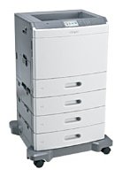
Lexmark C792dhe
Рейтинг
Снят с производства
Тип устройства
Принтер
Технология печати
лазерная
Макс. формат
A4
Число страниц в месяц
150000
Скорость печати
A4
47
Цветность печати
цветная
Общие характеристики |
|
---|---|
Размещение |
напольный |
Область применения |
большой офис |
Печать фотографий |
|
Копир |
|
Телефон |
|
Сканер |
|
Факс |
|
Макс. формат |
A4 |
Тип устройства |
Принтер |
Число страниц в месяц |
150 000 |
Цветность печати |
цветная |
Тип |
лазерный/светодиодный |
Технология печати |
лазерная |
Принтер |
|
Прямая печать |
![]() |
Двусторонняя печать |
![]() |
Пигментные чернила |
|
Печать без полей |
|
Количество цветов |
4 |
Макс, разрешение для ч/б печати |
|
По X | 1 200 |
По Y | 1 200 |
Скорость ч/б печати |
|
A4 | 47 |
Время выхода первого отпечатка |
|
Ч/б | 8 |
Цветн, | 8,5 |
Сканер |
|
Стандарт TWAIN |
|
Отправка изображения по e-mail |
|
Слайд-адаптер |
|
Стандарт WIA |
|
Расходные материалы |
|
Количество картриджей |
4 |
Печать на: |
|
Пленках |
![]() |
Глянцевой бумаге |
![]() |
Конвертах |
![]() |
Матовой бумаге |
![]() |
Карточках |
![]() |
Этикетках |
![]() |
Рулоне |
|
Фотобумаге |
|
CD/DVD |
|
Факс |
|
Цветной |
|
Телефон |
|
АОН |
|
Беспроводная трубка |
|
Проводная трубка |
|
Caller ID |
|
Автоответчик |
|
Стандарт DECT |
|
Спикерфон |
|
Шрифты и языки управления |
|
Языки управления |
|
![]() |
|
PostScript |
![]() |
PostScript 3 |
![]() |
PPDS |
![]() |
PCL 6 |
![]() |
PCL 5c |
![]() |
PostScript 2 |
|
Количество установленных шрифтов |
|
PostScript | 158 |
PCL | 84 |
PPDS | 44 |
Лотки |
|
Емкость лотка ручной подачи |
100 |
Подача бумаги |
|
Максимальная | 2 300 |
Стандартная | 2 300 |
Вывод бумаги |
|
Максимальный | 1 000 |
Стандартный | 500 |
Финишер |
|
Сортер |
|
Брошюровщик |
|
Степлер |
|
Интерфейсы |
|
USB |
![]() |
Веб-интерфейс |
![]() |
Ethernet (RJ-45) |
![]() |
Bluetooth |
|
Wi-Fi |
|
FireWire (IEEE 1394) |
|
LPT |
|
AirPrint |
|
Инфракрасный порт |
|
RS-232 |
|
Устройство для чтения карт памяти |
|
Версия USB |
2,0 |
Память/Процессор |
|
Объем памяти |
1 024 |
Частота процессора |
1 200 |
Макс, объем памяти |
1 536 |
Дополнительная информация |
|
Экран |
|
Работа от аккумулятора |
|
Диагональ дисплея |
4,3 |
Поддержка ОС |
|
DOS |
|
Mac OS |
![]() |
Windows |
![]() |
Уровень шума |
|
В режиме ожидания | 25 |
При работе | 52 |
Габариты |
|
Ширина |
663 |
Глубина |
657 |
Высота |
1 028 |
Вес |
105 |
Модули
High-capacity output stacker
High-capacity output stacker (continued)
Left
Optional 550-sheet drawer assembly
Top, right, and front covers
Front (continued)
Optional 550-sheet tray
Left (continued)
Finisher assembly (continued)
Optional 2000-sheet high-capacity feeder
Rear
Left and rear covers
Front
Finisher stapler assembly
Finisher assembly
Детали Rear
Деталь: | Left access door assembly |
Парткод: | 40X7234 |
Деталь: | Backup redrive roller |
Парткод: | 40X7238 |
Деталь: | REAR COVER |
Парткод: | 40X7231 |
Деталь: | Sensor (bin full receive) |
Парткод: | 40X5544 |
Деталь: | Finisher bin-full spring |
Парткод: | 40X7240 |
Деталь: | LED clear lens |
Парткод: | 40X5727 |
Деталь: | Standard output bin LED |
Парткод: | 40X5545 |
Деталь: | Bottom cover |
Парткод: | 40X7239 |
Деталь: | Sensor (finisher bin media present) |
Парткод: | 40X4618 |
Деталь: | Output bin extension |
Парткод: | 40X4619 |
Деталь: | Finisher controller card assembly |
Парткод: | 40X7241 |
Деталь: | Sensor (bin full send) |
Парткод: | 40X4626 |
Деталь: | FRONT COVER |
Парткод: | 40X7232 |
Деталь: | TOP COVER |
Парткод: | 40X7233 |
Деталь: | Sensor (stapler pass thru) |
Парткод: | 40X5906 |
Деталь: | Beacon housing |
Парткод: | 40X7237 |
Деталь: | Beacon clear lens |
Парткод: | 40X7236 |
Деталь: | Left access beacon |
Парткод: | 40X7235 |
Деталь: | Rear media stack flap |
Парткод: | 40X7244 |
Деталь: | Front media stack flap |
Парткод: | 40X7245 |
Деталь: | LED clear lens |
Парткод: | 40X7243 |
Деталь: | Rear tamper motor assembly |
Парткод: | 40X4622 |
Деталь: | Tamper recoil spring |
Парткод: | 40X4624 |
Деталь: | Tamper front and rear paddle sensor |
Парткод: | 40X7247 |
Деталь: | Tamper drive belt |
Парткод: | 40X4623 |
Деталь: | Front tamper motor assembly |
Парткод: | 40X4621 |
Деталь: | Output beacon card |
Парткод: | 40X7242 |
Деталь: | Paddle drive motor |
Парткод: | 40X4615 |
Деталь: | Redrive parts packet |
Парткод: | 40X7133 |
Деталь: | ITU autoconnect cable |
Парткод: | 40X7166 |
Деталь: | Sensors parts packet |
Парткод: | 40X7163 |
Деталь: | Staging deflector assembly with sensors |
Парткод: | 40X7146 |
Деталь: | Fuser/MPF/autocomp parts packet |
Парткод: | 40X7172 |
Деталь: | Fuser assembly, 115 V |
Парткод: | 40X7100 |
Деталь: | Fuser assembly, 220 V |
Парткод: | 40X7101 |
Деталь: | Fuser assembly, 100 V |
Парткод: | 40X7102 |
Деталь: | Lower frame cable cover |
Парткод: | 40X7164 |
Деталь: | Redrive motor assembly |
Парткод: | 40X7132 |
Деталь: | 550-sheet tray controller card assembly |
Парткод: | 40X6100 |
Деталь: | Anti-tip latch assembly |
Парткод: | 40X6101 |
Деталь: | 550-sheet/2000-sheet input option sensor pack |
Парткод: | 40X6274 |
Деталь: | 550-sheet tray pick assembly |
Парткод: | 40X6103 |
Деталь: | Pick roll assembly |
Парткод: | 40X6104 |
Деталь: | Printhead access cover |
Парткод: | 40X7109 |
Деталь: | Printhead assembly |
Парткод: | 40X7127 |
Деталь: | SPEAKER |
Парткод: | 40X7117 |
Деталь: | Top cover assembly with output option cable |
Парткод: | 40X7108 |
Деталь: | Top cap cover |
Парткод: | 40X7110 |
Деталь: | RIGHT COVER |
Парткод: | 40X7120 |
Деталь: | Standard media tray (550-sheet media tray assembly) |
Парткод: | 40X6099 |
Деталь: | Front access door and pivot |
Парткод: | 40X7111 |
Деталь: | Waste toner left cover with beacon |
Парткод: | 40X7125 |
Деталь: | Logo panel |
Парткод: | 40X7113 |
Деталь: | OP panel bezel, 210 (3 bezels) |
Парткод: | 40X7118 |
Деталь: | OP panel bezel, 230 (3 bezels) |
Парткод: | 40X7119 |
Деталь: | OP panel UICC card |
Парткод: | 40X7115 |
Деталь: | Bin-full flag |
Парткод: | 40X7124 |
Деталь: | OP panel cover assembly with buttons |
Парткод: | 40X7114 |
Деталь: | OP panel display: 4.3 LCD touch screen |
Парткод: | 40X7116 |
Деталь: | Cartridge memory block with sensor |
Парткод: | 40X7142 |
Деталь: | Paper pick mechanism assembly |
Парткод: | 40X7160 |
Деталь: | Pick tire roll assembly |
Парткод: | 40X6104 |
Деталь: | Cartridge contact block assembly |
Парткод: | 40X7143 |
Деталь: | Media tray rails (1 right, 1 left) |
Парткод: | 40X7126 |
Деталь: | 550-sheet drawer assembly |
Парткод: | 40X6102 |
Деталь: | 550-sheet media tray assembly |
Парткод: | 40X6099 |
Деталь: | Paper path redrive assembly |
Парткод: | 40X7134 |
Деталь: | Left access door pistons parts packet |
Парткод: | 40X7153 |
Деталь: | Fuser system card and LVPS cable with cable ties |
Парткод: | 40X7165 |
Деталь: | ITU module assembly |
Парткод: | 40X7103 |
Деталь: | Rear media stack flap |
Парткод: | 40X7244 |
Деталь: | Front media stack flap |
Парткод: | 40X7245 |
Деталь: | LED clear lens |
Парткод: | 40X7243 |
Деталь: | Rear tamper motor assembly |
Парткод: | 40X4622 |
Деталь: | Tamper recoil spring |
Парткод: | 40X4624 |
Деталь: | Tamper front and rear paddle sensor |
Парткод: | 40X7247 |
Деталь: | Tamper drive belt |
Парткод: | 40X4623 |
Деталь: | Front tamper motor assembly |
Парткод: | 40X4621 |
Деталь: | Output beacon card |
Парткод: | 40X7242 |
Деталь: | Paddle drive motor |
Парткод: | 40X4615 |
Деталь: | 2000-sheet high-capacity feeder pick roll assembly |
Парткод: | 40X6275 |
Деталь: | 2000-sheet high-capacity feeder pick assembly |
Парткод: | 40X6119 |
Деталь: | 550-sheet/2000-sheet input option sensor pack |
Парткод: | 40X6274 |
Деталь: | Tray latch |
Парткод: | 40X4585 |
Деталь: | 2000-sheet high-capacity feeder controller card assembly |
Парткод: | 40X6276 |
Деталь: | Anti-tip latch assembly |
Парткод: | 40X6101 |
Деталь: | 2000-sheet high-capacity feeder lift drive motor assembly |
Парткод: | 40X6486 |
Деталь: | 2000-sheet high-capacity feeder media tray assembly |
Парткод: | 40X6115 |
Деталь: | 2000-sheet high-capacity feeder jam clearance cover |
Парткод: | 40X6118 |
Деталь: | 2000-sheet high-capacity feeder drive assembly |
Парткод: | 40X6116 |
Деталь: | Bolivia, Peru (8 ST) |
Парткод: | 40X0269 |
Деталь: | Japan (8 ST) |
Парткод: | 40X0270 |
Деталь: | UK, Ireland (8 ST) |
Парткод: | 40X0271 |
Деталь: | Chile, Uruguay (8 ST) |
Парткод: | 40X0273 |
Деталь: | Israel (8 ST) |
Парткод: | 40X0275 |
Деталь: | Argentina (8 ST) |
Парткод: | 40X0288 |
Деталь: | Australia (8 ST) |
Парткод: | 40X0301 |
Деталь: | PRC (8 ST) |
Парткод: | 40X0303 |
Деталь: | Switzerland (8 ST) |
Парткод: | 40X1772 |
Деталь: | South Africa (8 ST) |
Парткод: | 40X1773 |
Деталь: | Denmark (8 ST) |
Парткод: | 40X1774 |
Деталь: | Taiwan (2.5 m ST) |
Парткод: | 40X1791 |
Деталь: | Korea (2.5 m ST) |
Парткод: | 40X1792 |
Деталь: | Europe (8 ST) |
Парткод: | 40X3141 |
Деталь: | Brazil (8 ST) |
Парткод: | 40X4596 |
Деталь: | U.S., Canada (8 ST) |
Парткод: | 40X7104 |
Деталь: | MAIN FAN |
Парткод: | 40X7131 |
Деталь: | LVPS exit duct |
Парткод: | 40X7128 |
Деталь: | LVPS fan |
Парткод: | 40X7129 |
Деталь: | MPF drive assembly |
Парткод: | 40X7152 |
Деталь: | Fuser drive assembly |
Парткод: | 40X7135 |
Деталь: | Waste toner gears parts packet |
Парткод: | 40X7162 |
Деталь: | Low-voltage power supply (LVPS) with thermistor retainer |
Парткод: | 40X7137 |
Деталь: | System board and HVPS card parts packet |
Парткод: | 40X7140 |
Деталь: | System board |
Парткод: | 40X7136 |
Деталь: | Exit cooling duct assembly |
Парткод: | 40X7155 |
Деталь: | EP drive assembly |
Парткод: | 40X7144 |
Деталь: | MPF sensor plate assembly |
Парткод: | 40X7151 |
Деталь: | Left cover assembly with LVPS power switch cable |
Парткод: | 40X7122 |
Деталь: | MPF pick tire roll assembly |
Парткод: | 40X7149 |
Деталь: | MPF paper pick assembly |
Парткод: | 40X7148 |
Деталь: | Duplex assembly |
Парткод: | 40X7156 |
Деталь: | Left access door assembly |
Парткод: | 40X7123 |
Деталь: | MPF door assembly |
Парткод: | 40X7147 |
Деталь: | Lower left cover |
Парткод: | 40X7121 |
Деталь: | Belts parts packet |
Парткод: | 40X7157 |
Деталь: | MPF pick parts packet |
Парткод: | 40X7150 |
Деталь: | Pins and pads parts packet |
Парткод: | 40X7174 |
Деталь: | System board shield door |
Парткод: | 40X7138 |
Деталь: | Rear upper cover |
Парткод: | 40X7106 |
Деталь: | REAR COVER |
Парткод: | 40X7105 |
Деталь: | ITU contact block assembly |
Парткод: | 40X7145 |
Деталь: | Cartridge blower assembly |
Парткод: | 40X7130 |
Деталь: | Cartridge rail assembly |
Парткод: | 40X7141 |
Деталь: | Sensors parts packet |
Парткод: | 40X7163 |
Деталь: | Waste toner tray bracket |
Парткод: | 40X7161 |
Деталь: | HVPS assembly with cable shield |
Парткод: | 40X7139 |
Деталь: | Housing interlock assembly with sensor |
Парткод: | 40X7112 |
Деталь: | Staging paper path reference edge assembly |
Парткод: | 40X7158 |
Деталь: | Left access door assembly |
Парткод: | 40X7234 |
Деталь: | Backup redrive roller |
Парткод: | 40X7238 |
Деталь: | REAR COVER |
Парткод: | 40X7231 |
Деталь: | Sensor (bin full receive) |
Парткод: | 40X5544 |
Деталь: | Finisher bin-full spring |
Парткод: | 40X7240 |
Деталь: | LED clear lens |
Парткод: | 40X5727 |
Деталь: | Standard output bin LED |
Парткод: | 40X5545 |
Деталь: | Bottom cover |
Парткод: | 40X7239 |
Деталь: | Sensor (finisher bin media present) |
Парткод: | 40X4618 |
Деталь: | Output bin extension |
Парткод: | 40X4619 |
Деталь: | Finisher controller card assembly |
Парткод: | 40X7241 |
Деталь: | Sensor (bin full send) |
Парткод: | 40X4626 |
Деталь: | FRONT COVER |
Парткод: | 40X7232 |
Деталь: | TOP COVER |
Парткод: | 40X7233 |
Деталь: | Sensor (stapler pass thru) |
Парткод: | 40X5906 |
Деталь: | Beacon housing |
Парткод: | 40X7237 |
Деталь: | Beacon clear lens |
Парткод: | 40X7236 |
Деталь: | Left access beacon |
Парткод: | 40X7235 |
Коды ошибок
110.xx
120.xx
121.00...121.59
125.00...125.69
126.08...126.09
133.xx
141.01...141.09
142.01...142.09
143.01...143.09
144.01...144.09
145.01...145.1
146.01...146.22
147.01...147.22
149.01...149.22
150.01...150.22
151.01...151.09
171.01...171.03
172.01...172.03
173.01...173.03
200.01
200.02
200.03, 200.08
200.04
200.05, 200.07
200.21, 200.22
200.31
200.32
200.33, 200.38
200.35, 200.37
200.40
200.41
200.42
200.43, 200.48
200.44
200.45, 200.47
200.49
201.01, 201.51
201.02, 201.52
201.03, 201.05, 201.07, 201.08
201.04, 201.54
201.42
201.53, 201.55, 201.57, 201.58
202.01, 202.51
202.02, 202.52
202.03, 202.08, 202.53
202.04, 202.54
202.05, 202.07
202.31
202.32
202.33, 202.38
202.34
202.35, 202.37
202.39
202.55, 202.57
202.58
203.01...203.07
203.21, 203.22
231.01...231.08
232.01...232.08
241.01
241.02
241.04, 241.05, 241.07
241.08
241.21, 241.22
24x.01
24x.03
24x.05
24x.08
250.02
250.03, 250.05
250.21 250.22
31
32
34
35
37
38
39
50
51
52
53
54
55
56
57
58
59
61
62
63
64
80
80.41
82
82.41
83.xx
84
84.11
88.xx
900.00...900.99
910.xx...915.xx
938.01
938.02
938.03...938.04
938.05...938.08
938.09
938.10
938.11...938.14
938.15
938.16
938.18
938.19
938.20
938.21
938.22
938.23
938.24
938.25...938.26
938.27...938.30
938.31
950.00...950.29
952.01...952.99
953.01...953.99
954.01...954.99
955.00...955.99
956.00...956.99
957.00...957.99
958.00...958.99
959.00...959.05
959.20...959.28
960.00...960.99
961.00...961.99
964.00...964.99
975.00...975.99
976.00...976.99
982.00...982.12
990.00...990.29
990.01
991.00...991.99
Описание
Error code: | 110.xx |
Description: | Printhead Error An error has occurred in the printhead |
Remedy: | 1 View the Event Log: 1. Turn off the printer, press and hold 3 and 6 and turn on the printer. 2. Select EVENT LOG > Display Log. Has a 110.xx error occurred three times or more? Replace the printhead. See “Printhead removal, installation, and alignment”. Go to step 2. 2 Turn the printer off, and open the system board shield. Check the printhead cables (A) in connectors JMM1, JPH1, and JPH2 for proper connection to the system board. Are the cables properly connected? Go to step 3. Reseat the cables. 3 Check the printhead cables in connectors JMM1, JPH1, and JPH2 for damage. Are the cables damaged? Replace the printhead. See “Printhead removal, installation, and alignment”. Go to step 4. 4 Measure the resistance across fuse F13 on the system board. Is the fuse blown? Replace the system board. See “System board removal”. Go to step 5. 5 Perform the printhead verification to check whether the new printhead solves the problem. See “Printhead verification”. Did the printhead motor pass the test? Replace the printhead. See “Printhead removal, installation, and alignment”. Replace the system board. See “System board removal”. |
Error code: | 120.xx |
Description: | Fuser Motor Error An error has occurred in the fuser motor. |
Remedy: | 1 Turn the printer off, open the system board shield, and remove the RIP card shield. Check the cable in connector JYF1 (BLDC Y & Fuser cable) for proper connection to the system board. Is the cable properly connected? Go to step 2. Reseat the cable. 2 Check the cable for damage. Is the cable damaged? Replace the BLDC Y & Fuser cable. See “EP drive assembly removal”. Go to step 3. 3 Remove the rear cover. See “Rear cover removal”. Check the cable (B) for proper connection to the fuser motor. Is the cable properly connected? Go to step 4. Reseat the cable. 4 Is the BLDE Y & Fuser cable damaged? Replace the BLDC Y & Fuser cable. See “EP drive assembly removal”. Go to step 5. 5 Replace the fuser motor. See “Fuser drive assembly removal”. Does the problem reoccur? Replace the system board. See “System board removal”. Problem solved. |
Error code: | 121.00...121.59 |
Description: | Fuser Error An error has occurred in the fuser. |
Remedy: | 1 Replace the fuser. See “Fuser assembly removal”. Does the error clear? Problem solved. Go to step 2. 2 Open the system board shield. Check the cable in connector JFSR1 (D) for proper connection to the system board. Is the cable properly connected? Go to step 3. Reseat the cable. 3 Check the cable for damage. Is the cable damaged? Replace the Fuser and system card LVPS cable. See “Fuser system card and LVPS cable removal”. Go to step 4. 4 Check the cable (F) on the LVPS for proper connection. Is the cable properly connected? Go to step 5. Reseat the cable. 5 Check the cable on the LVPS for damage. Is the cable damaged? Replace the Fuser and system card LVPS cable. See “Fuser system card and LVPS cable removal”. Go to step 6. 6 Open the left access door, remove the two screws (A), and pull out the fuser autoconnect enough to check the cable for proper connection. Is the cable properly connected? Go to step 7. Reseat the cable. 7 Check the cable for damage. Is the cable damaged? Replace the Fuser and system card LVPS cable. See “Fuser system card and LVPS cable removal”. Reseat the cable. |
Error code: | 125.00...125.69 |
Description: | ITU Error An error has occurred in the ITU. |
Remedy: | 1 Replace the ITU assembly. See “ITU assembly removal”. Does the error clear? Problem solved. Go to step 2. 2 Turn the printer off, open the system board shield, and remove the RIP card shield. Check the ITU autoconnect cable in connector JITM1 (B) for proper connection to the system board. Is the cable properly connected? Go to step 3. Reseat the cable. 3 Check the cable for damage. Is the cable damaged? Replace the ITU autoconnect cable. See “ITU autoconnect removal”. Go to step 4. 4 Measure the resistance across fuse F15 on the system board. Is the fuse blown? Replace the system board. See “System board removal”. Replace the ITU autoconnect cable. See “ITU autoconnect removal”. |
Error code: | 126.08...126.09 |
Description: | LVPS Error An error has occurred in the LVPS. |
Remedy: | 1 Ask the customer if they’re having any problem with their power lines, e.g., power outages or power failures. Is the customer having power line problems? Do nothing. Go to step 2. 2 Turn the printer off, open the system board shield, and remove the connector shield. Check the cables in connector JLVPS1 and J9 (E) for proper connection to the system board. Are the cables properly connected? Go to step 2. Reseat the cables. 3 Check the cables for damage. Are the cables damaged? Replace the LVPS. See “Low-voltage power supply (LVPS) removal”. Replace the system board. See “System board removal”. |
Error code: | 133.xx |
Description: | Cartridge sensor Error An error has occurred in a cartridge sensor. 133.01 = black, 133.02 = cyan, 133.03 = magenta, and 133.04 = yellow. 133.05 A timeout error has occurred while waiting for the indicated cartridge. |
Remedy: | 1 a. Power off the printer. b. Enter the Diagnostics mode, (press and hold 3 and 6, while turning on the printer). c. Select Base Sensor Test. d. Select the failing sensor: e. Remove all the cartridges. f. Defeat the front access door switch with a screwdriver as shown. g. Depress the arm of the failing sensor. Replace the cartridge. Go to step 2. Error code Sensor 133.01 K TMC sensor 133.02 C TMC sensor 133.03 M TMC sensor 133.04 Y TMC sensor Does the sensor go from “Open” to “Close?” 2 Turn the printer off and open the system board shield. Check the cables in the indicated connectors for proper connection to the system board. The cables are interchangeable on the terminals, so check all four cables for any 133.xx error. Are the cables properly connected? Go to step 3. Reseat the cable. 3 Check the cables in the indicated connectors for proper connection to the system board. 133.01 Black—D (JCMKM1) 133.02 Cyan—C (JCMCY1) 133.03 Magenta—D (JCMKM1) 133.04 Yellow—C (JCMCY1) Are the cables properly connected? Go to step 4. Reseat the cable. 4 Check the cables in connectors JCMKM1 and JCMCY1 for damage, and then remove all four cartridges and check the other ends of the cables connected to the sensors on the memory blocks. 133.01 Black—B (JCMKM15 Replace the indicated cartridge memory block and cable. See “Cartridge memory block removal”. Set up cartridge to force a TMC. 1. Take the cartridge indicated by the error code, and rotate the developer input gear (E) clockwise to locate the tab as indicated. 2. Rotate the toner metering paddle cam (G) up to force the tab (F) until it sticks out. Problem solved. Replace the system board. See “System board removal”.) 133.02 Cyan—A (JCMCY1) 133.03 Magenta—B (JCMKM1) 133.04 Yellow—A (JCMCY1) Is either cable damaged? Replace the cable. Go to step 3. 3. Rotate the developer input gear clockwise until the tab (H) is up against the tab on the larger gear (J). Print two demo pages: 1. Replace all cartridges. 2. Turn on the machine. 3. Select Menu > Reports > Print Demo > Demo Page. 4. Do step three again to get the second demo page. Does this fix the problem? |
Error code: | 141.01...141.09 |
Description: | Black cartridge motor error An error has occurred in the black cartridge motor. |
Remedy: | 1 Turn the printer off, open the system board shield, and remove the connector shield. Check the cable in the connector JKI1 (BLDC K & ITU cable) for proper connection to the system board. Is the cable properly connected? Go to step 2. Reseat the cable. 2 Check the cable in the connector JKI1 (BLDC K & ITU cable) for damage. Is the cable damaged? Replace the BLDC K ITU cable. See “EP drive assembly removal”. Go to step 3. 3 Measure the resistance across the fuse F10 on the system board. Is the fuse blown? Replace the system board. See “System board removal”. Go to step 4. 4 Remove the system board cage. See “System board cage with board removal”. Check the cable connected to the black cartridge motor. Is the cable connected properly Go to step 5. Reseat the cable. 5 Replace the EP drive assembly. See “EP drive assembly removal”. Does the error reoccur? Replace the system board. See “System board removal”. Problem solved. |
Error code: | 142.01...142.09 |
Description: | Cyan cartridge motor error An error has occurred in the cyan cartridge motor. |
Remedy: | 1 Turn the printer off, open the system board shield, and remove the connector shield. Check the cable in the connector JCM1 (BLDC C&M cable) for proper connection to the system board. Is the cable properly connected? Go to step 2. Reseat the cable. 2 Check the cable for damage. Is the cable damaged? Replace the BLDC C&M cable. See “EP drive assembly removal”. Go to step 3. 3 Measure the resistance across the fuse F4 on the system board. Is the fuse blown? Replace the system board. See “System board removal”. Go to step 4. 4 Remove the system board cage. See “System board cage with board removal”. Check the cable connected to the cyan cartridge motor. Is the cable connected properly Go to step 5. Reseat the cable. 5 Replace the EP drive assembly. See “EP drive assembly removal”. Does the error reoccur? Replace the system board. See “System board removal”. Problem solved. |
Error code: | 143.01...143.09 |
Description: | Magenta cartridge motor error An error has occurred in the magenta cartridge motor. |
Remedy: | 1 Turn the printer off, open the system board shield, and remove the connector shield. Check the cable in the connector JCM1 (BLDC C&M cable) for proper connection to the system board. Is the cable properly connected? Go to step 2. Reseat the cable. 2 Check the cable for damage. Is the cable damaged? Replace the BLDC C&M cable. See “EP drive assembly removal”. Go to step 3. 3 Measure the resistance across the fuse F7 on the system board. Is the fuse blown? Replace the system board. See “System board removal”. Go to step 4. 4 Remove the system board cage. See “System board cage with board removal”. Check the cable connected to the magenta cartridge motor. Is the cable connected properly Go to step 5. Reseat the cable. 5 Replace the EP drive assembly. See “EP drive assembly removal”. Does the error reoccur? Replace the system board. See “System board removal”. Problem solved. |
Error code: | 144.01...144.09 |
Description: | Yellow cartridge motor error An error has occurred in the yellow cartridge motor. |
Remedy: | 1 Turn the printer off, open the system board shield, and remove the connector shield. Check the cable in the connector JYF1 (BLDC Y & 2 Check the cable for damage. Is the cable damaged? Replace the BLDC Y & Fuser cable. See “EP drive assembly removal”. Go to step 3. 3 Measure the resistance across the fuse F1 on the system board. Is the fuse blown? Replace the system board. See “System board removal”. Go to step 4. 4 Remove the system board cage. See “System board cage with board removal”. Check the cable connected to the yellow cartridge motor. Is the cable connected properly Go to step 5. Reseat the cable. 5 Replace the EP drive assembly. See “EP drive assembly removal”. Does the error reoccur? Replace the system board. See “System board removal”. Problem solved.Fuser cable) for proper connection to the system board. Is the cable properly connected? Go to step 2. Reseat the cable. |
Error code: | 145.01...145.1 |
Description: | Retract Motor Error An error has occurred in the all-color retract motor. |
Remedy: | 1 Replace the ITU assembly. See “ITU assembly removal”. Does the error clear? Problem solved. Go to step 2. 2 Turn the printer off, open the system board shield, and remove the RIP card shield. Check the ITU autoconnect cable in connector JITM1 (B) for proper connection to the system board. Is the cable properly connected? Go to step 3. Reseat the cable. 3 Check the cable for damage. Is the cable damaged? Replace the ITU autoconnect cable. See “ITU autoconnect removal”. Go to step 4. 4 Measure the resistance across fuse F15 on the system board. Is the fuse blown? Replace the system board. See “System board removal”. Replace the ITU autoconnect cable. See “ITU autoconnect removal”. |
Error code: | 146.01...146.22 |
Description: | Autocomp Motor Error Tray 1 motor has failed. |
Remedy: | 1 Turn the printer off, and open the system board shield. Check the cable in connector JTRAY1 (A) for proper connection to the system board. Is the cable properly connected? Go to step 2. Reseat the cable. 2 Check the cable for damage. Is the cable damaged? Replace the Tray 1 machine side cable. See “Autocomp W2W cable”. Go to step 3. 3 Remove the standard media tray. Check the cable (A) from the paper pick mechanism assembly to the printer. Is the cable properly connected? Go to step 4. Reseat the cable. 4 Remove the paper pick mechanism assembly. See “Paper pick mechanism assembly removal”. Does the error reoccur? Replace the system board. See “System board removal”. Problem solved. |
Error code: | 147.01...147.22 |
Description: | Staging Motor Error The staging motor has failed. |
Remedy: | 1 Turn the printer off, and open the system board shield. Check the cable in connector JSTAG1 (staging motor cable) for proper connection to the system board. Is the cable properly connected? Go to step 2. Reseat the cable. 2 Check the cable for damage. Is the cable damaged? Replace the staging motor cable. See “Staging paper path reference edge assembly removal” to access the cable. Go to step 3. 3 Remove the LVPS. See “Low-voltage power supply (LVPS) removal”. Check the cable connection to the motor. Is the cable connected correctly to the staging motor? Go to step 4. Reseat the cable. 4 Replace the staging paper path reference edge assembly. See “Staging paper path reference edge assembly removal”. Dose the error reoccur? Replace the system board. See “System board removal”. Problem solved. |
Error code: | 149.01...149.22 |
Description: | Paper Path Redrive Motor Error The paper path redrive motor has failed. |
Remedy: | 1 Turn the printer off, and open the system board shield. Check the cable in connector JRDR1 for proper connection to the system board. Is the cable properly connected? Go to step 2. Reseat the cable. 2 Replace the staging deflector assembly. See “Staging deflector assembly removal”. Does the error reoccur? Replace the system board. See “System board removal”. Problem solved. |
Error code: | 150.01...150.22 |
Description: | Motor Error Duplex motor has failed. |
Remedy: | 1 Open the left access door assembly, and check the duplex assembly gears for damage. Is the duplex assembly damaged? Replace the duplex assembly. See “Duplex assembly removal”. Go to step 2. 2 Turn the printer off, and open the system board shield. Check the cable in connector JDUPL1 (Duplex motor cable) for proper connection to the system board. Is the cable properly connected? Go to step 3. Reseat the cable. 3 Check the cable for damage. Is the cable damaged? Replace the duplex motor cable. See “Staging paper path reference edge assembly removal” to access the cable. Go to step 4. 4 Remove the rear cover and the left cover. See“Rear cover removal” and “Left cover removal”. Check the cable connection to the duplex motor. Is the cable connected correctly to the motor? Go to step 5. Reseat the cable. 5 Replace the housing interlock assembly. See “Housing interlock assembly removal”. Dose the error reoccur? Replace the system board. See “System board removal”. Problem solve |
Error code: | 151.01...151.09 |
Description: | ITU Motor Error An error has occurred in the ITU motor. |
Remedy: | 1 Turn the printer off, open the system board shield, and remove the connector shield. Check the cable in connector JKI1 (BLDC K & ITU cable) for proper connection to the system board. Is the cable properly connected? Go to step 2. Reseat the cable. 2 Check the cable in the connector JKI1 (BLDC K & ITU cable) for damage. Is the cable damaged? Replace the BLDC K & ITU cable. See “EP drive assembly removal”. Go to step 3. 3 Remove the rear cover. See “Rear cover removal”. Check the cable connection to the ITU motor. Is the cable properly connected? Go to step 4. Reseat the cable. 4 Replace the EP drive assembly. See “EP drive assembly removal”. Does the error reoccur? Replace the system board. See “System board removal”. Problem solved. |
Error code: | 171.01...171.03 |
Description: | Main Fan Error An error has occurred in the main fan. |
Remedy: | 1 Turn the printer off, and open the system board shield. Check the cable in connector JM1 for proper connection to the system board. Is the cable properly connected? Go to step 2. Reseat the cable. 2 Replace the main fan. See “Main fan removal”. Does the error reoccur? Replace the system board. See “System board removal”. Problem solved. |
Error code: | 172.01...172.03 |
Description: | LVPS Fan Error An error has occurred in the LVPS fan. |
Remedy: | 1 Turn the printer off, and open the system board shield. Check the cable in connector JL1 for proper connection to the system board. Is the cable properly connected? Go to step 2. Reseat the cable. 2 Replace the LVPS fan. See “LVPS fan removal”. Does the error reoccur? Replace the system board. See “System board removal”. Problem solved. |
Error code: | 173.01...173.03 |
Description: | Blower Fan Error An error has occurred in the blower fan. |
Remedy: | 1 Turn the printer off, and open the system board shield. Check the cable in connector JBLW1 (blower & right side waste cable) for proper connection to the system board. Is the cable properly connected? Go to step 2. Reseat the cable. 2 Check the cable in the connector JBLW1 (blower & right side waste cable) for damage. Is the cable damaged? Replace the blower & right side waste cable. See “Printhead access cover removal” to access the cable on top of the frame. Go to step 3. 3 Remove the cartridge blower assembly. See “Cartridge blower assembly removal”. Check the cable connected to the assembly. Is the cable connected to the blower fan? Go to step 4. Reseat the cable. 4 Replace the cartridge blower assembly. See “Cartridge blower assembly removal”. Does the error reoccur? Replace the system board. See “System board removal”. Problem solved. |
Error code: | 200.01 |
Display: | 200.01 |
Description: | Input sensor is made when printer tries to print from an idle state. Possible causes: • Paper jam leaving page over sensor • Defective input sensor • Faulty system card |
Remedy: | • Check for anything in the paper path that might cause the paper to jam. |
Error code: | 200.02 |
Description: | The main input sensor never became uncovered from the printer and the driver. the sheet ahead. |
Remedy: | First, remove the PC kit and paper or debris at the input sensor. Then, inspect the flag on the input sensor. It should rotate freely. Replace the sensor if necessary. Finally, check the paper size settings in the printer and the driver. |
Error code: | 200.03, 200.08 |
Description: | Input sensor is never made or made late. Possible causes: • Faulty input sensor • Faulty staging deflector assembly • Faulty autocomp assembly |
Remedy: | 1 Remove the input tray. Are the pick tires worn? Replace the pick tires. See “Pick rolls removal”. Go to step 2. 2 Open the left access door. Check the input sensor flag (A) for damage. Is the input sensor flag damaged? Replace the input sensor. See “Sensor (input, S1, narrow media, near narrow media) removal”. Go to step 3. 3 Is the staging deflector assembly damaged? Replace the staging deflector assembly. See “Staging deflector assembly removal”. Go to step 4. 4 Turn the printer off, and open the system board shield. Check the cable in connector JPP2 for proper connection to the system board. Is the cable properly connected? Go to step 5. Reseat the cable. 5 Check the cable in connector JPP2 for any other damage. Is the cable damaged? Replace the paper path cable. See “Paper path cables”. Go to step 6. 6 Remove the staging deflector assembly. See “Staging deflector assembly removal”. Is the cable connected correctly? Go to step 7. Reseat the cable. 7 Replace the input sensor. See “Sensor (input, S1, narrow media, near narrow media) removal”. Does the error reoccur? Replace the System Board. See “System board removal”. Problem solved |
Error code: | 200.04 |
Description: | Input sensor covered too quickly • Paper pre-staged in paper path. • Wrong configuration ID causes engine to assume 500-sheet paper path on 250-sheet model. • Bouncy input sensor. |
Remedy: | • Check MPF and friction pad. • Fan media and stack flat in tray or MPF. • Use different media. • Check config ID. |
Error code: | 200.05, 200.07 |
Description: | 200.05 Media reached the sensor (input) but did not clear it within the specified time. (Media source = MPF tray) 200.07 Media reached the sensor (input) but did not clear it within the specified time. |
Remedy: | Step 1 Check the media size setup and tray guides for all media trays. Does the media size, in use, match the size set for all media trays? Go to step 2. Replace the media, or change the media size setup. Step 2 Check the media trays for overfilling. Are any of the media trays overfilled? Remove any excess new media. Go to step 3. Step 3 Check the media condition in all media trays. Is any of the media in any of the media trays crumpled or damaged? Replace the damaged media. Go to step 4. |
Error code: | 200.21, 200.22 |
Description: | Staging motor stalled or is under speed. Possible causes: • Faulty staging motor • Faulty cable/connector • Faulty system board |
Remedy: | 1 Turn the printer off, and open the system board shield. Check the cable in connector JSTAG1 (staging motor cable) for proper connection to the system board. Is the cable properly connected? Go to step 2. Reseat the cable. 2 Check the cable for damage. Is the cable damaged? Replace the staging motor cable. See “Staging paper path reference edge assembly removal” to access the cable. Go to step 3. 3 Remove the LVPS. See “Low-voltage power supply (LVPS) removal”. Check the cable connection to the motor. Is the cable connected correctly to the staging motor? Go to step 4. Reseat the cable. 4 Replace the staging paper path reference edge assembly. See “Staging paper path reference edge assembly removal”. Dose the error reoccur? Replace the system board. See “System board removal”. Problem solved. |
Error code: | 200.31 |
Description: | Near narrow media sensor is made when the printer tries to print from an idle state. Possible causes: • Paper jam leaving paper over the sensor • Defective near narrow media sensor • Faulty system board |
Remedy: | 1 Open the left access door. Check the sensor flag for damage. A—Input sensor B—S1 sensor C—Narrow media sensor D—Near narrow media sensor Is the sensor flag damaged? Replace the input sensor. See “Sensor (input, S1, narrow media, near narrow media) removal”. Go to step 2. 2 Turn the printer off, and open the system board shield. Check the cable in connector JPP2 for proper connection to the system board. Is the cable properly connected? Go to step 3. Reseat the cable. 3 Check the cable in connector JPP2 for damage. Is the cable damaged? Replace the paper path cable. See “Paper path cables”. Go to step 4. 4 Remove the staging deflector assembly, and check the sensor cable connection. See “Staging deflector assembly removal”. A—Input sensor B—S1 sensor C—Narrow media sensor D—Near narrow media sensor Is the cable properly connected? Go to step 5. Reseat the cable. 5 Replace the sensor. “Sensor (input, S1, narrow media, near narrow media) removal” Does the error reoccur? Replace the system board. See “System board removal”. Problem solved. |
Error code: | 200.32 |
Description: | Detected sensor (control panel interlock) bounce. |
Remedy: | Step 1 Check the sensor (input) for proper operation. a Enter the diagnostic mode. b Select Base sensor test. c Observe the line item control panel door interlock. Does the display on the control panel change every time the sensing area of the above sensor is interrupted or blocked? Go to step 3. Go to step 2. Step 2 Check the above sensor for proper connection. Is the above sensor connected properly? Replace the sensor (control panel door interlock). Go to step 3. Replace the connection. Go to step 3. Step 3 Reset the machine. Does the error continue? Replace the controller board. See “Controller board removal”. Problem solved. |
Error code: | 200.33, 200.38 |
Description: | 200.33 Near narrow media sensor is never made or is made late. • Faulty input sensor • Faulty staging deflector assembly • Faulty autocomp assembly 200.38 Near narrow media sensor is never made or is made late. |
Remedy: | 1 Remove the input tray. Are the pick tires worn? Replace the pick tires. See “Pick rolls removal”. Go to step 2. 2 Open the left access door. Check the near narrow media sensor flag (D) for damage. Is the near narrow media sensor flag damaged? Replace the near narrow media sensor. See “Sensor (input, S1, narrow media, near narrow media) removal”. Go to step 3. 3 Is the staging deflector assembly damaged? Replace the staging deflector assembly. See “Staging deflector assembly removal”. Go to step 4. 4 Turn the printer off, and open the system board shield. Check the cable in connector JPP2 for proper connection to the system board. Is the cable properly connected? Go to step 5. Reseat the cable. 5 Check the cable in connector JPP2 for any other damage. Is the cable damaged? Replace the paper path cable. See “Paper path cables”. Go to step 6. 6 Remove the staging deflector assembly. See “Staging deflector assembly removal”. Is the cable connected correctly? Go to step 7. Reseat the cable. 7 Replace the near narrow media sensor. See “Sensor (input, S1, narrow media, near narrow media) removal”. Does the error reoccur? Replace the System Board. See “System board removal”. Problem solved. |
Error code: | 200.35, 200.37 |
Description: | Near narrow media sensor does not break or breaks late. • Incorrect paper settings • Incorrect paper loaded • Incorrect paper guide setting • ITU module failure • Lower guide failure • Paper pick mechanism failure • Near narrow media sensor failure |
Remedy: | 1 Reseat the ITU. Did the error clear? Problem solved. Go to step 2. 2 Open the left access door. Check the near narrow media sensor flag (D) for damage. Is the near narrow media sensor flag damaged? Replace the near narrow media sensor. See “Sensor (input, S1, narrow media, near narrow media) removal”. Go to step 3. 3 Is the staging deflector assembly damaged? Replace the staging deflector assembly. See “Staging deflector assembly removal”. Go to step 4. 4 Replace the ITU. Did the error clear? Problem solved. Go to step 5. 5 Remove the staging deflector assembly. See “Staging deflector assembly removal”. Is the cable connected correctly? Go to step 6. Reseat the cable. 6 Replace the near narrow media sensor. See “Sensor (input, S1, narrow media, near narrow media) removal”. Does the error reoccur? Replace the System Board. See “System board removal”. Problem solved. |
Error code: | 200.40 |
Description: | S1 sensor is made early. Possible causes: • Incorrect paper settings • Defective S1 sensor |
Remedy: | 1 Open the left access door. Check the S1 sensor flag (B) for damage. Is the S1 flag damaged? Replace the S1 sensor. See “Sensor (input, S1, narrow media, near narrow media) removal”. Go to step 2. 2 Remove the staging deflector assembly. See “Staging deflector assembly removal”. Is the S1 sensor (B) in the staging deflector assembly loose? Reseat the sensor and add a sensor retainer. See “Sensor (input, S1, narrow media, near narrow media) removal”. Contact your next level of support. |
Error code: | 200.41 |
Description: | Narrow media sensor is made when printer tries to print from an idle state. Possible causes: • Paper jam leaving page over sensor • Defective narrow media sensor • Faulty system board |
Remedy: | 1 Open the left access door. Check the sensor flag for damage. A—Input sensor B—S1 sensor C—Narrow media sensor D—Near narrow media sensor Is the sensor flag damaged? Replace the input sensor. See “Sensor (input, S1, narrow media, near narrow media) removal”. Go to step 2. 2 Turn the printer off, and open the system board shield. Check the cable in connector JPP2 for proper connection to the system board. Is the cable properly connected? Go to step 3. Reseat the cable. 3 Check the cable in connector JPP2 for damage. Is the cable damaged? Replace the paper path cable. See “Paper path cables”. Go to step 4. 4 Remove the staging deflector assembly, and check the sensor cable connection. See “Staging deflector assembly removal”. A—Input sensor B—S1 sensor C—Narrow media sensor D—Near narrow media sensor Is the cable properly connected? Go to step 5. Reseat the cable. 5 Replace the sensor. “Sensor (input, S1, narrow media, near narrow media) removal” Does the error reoccur? Replace the system board. See “System board removal”. Problem solved. |
Error code: | 200.42 |
Description: | Rogue sheet is at the manual feed sensor while flushing the paper path prior to declaring MPF source empty. |
Remedy: | Retry alignment. |
Error code: | 200.43, 200.48 |
Description: | 200.43 Narrow media sensor is never made or is made late. 200.48 Narrow media sensor is never made or is made late. |
Remedy: | 1 Remove the input tray. Are the pick tires worn? Replace the pick tires. See “Pick rolls removal”. Go to step 2. 2 Open the left access door. Check the narrow media sensor flag (C) for damage. Is the narrow media sensor flag damaged? Replace the narrow media sensor flag. See “Sensor (input, S1, narrow media, near narrow media) removal”. Go to step 3. 3 Is the staging deflector assembly damaged? Replace the staging deflector assembly. See “Staging deflector assembly removal”. Go to step 4. 4 Turn the printer off, and open the system board shield. Check the cable in connector JPP2 for proper connection to the system board. Is the cable properly connected? Go to step 5. Reseat the cable. 5 Check the cable in connector JPP2 for any other damage. Is the cable damaged? Replace the paper path cable. See “Paper path cables”. Go to step 6. 6 Remove the staging deflector assembly. See “Staging deflector assembly removal”. Is the cable connected correctly? Go to step 7. Reseat the cable. 7 Replace the narrow media sensor. See “Sensor (input, S1, narrow media, near narrow media) removal”. Does the error reoccur? Replace the system board. See “System board removal”. Problem solved. |
Error code: | 200.44 |
Description: | Narrow media sensor broke early. Possible causes: • Incorrect paper settings • Defective narrow media sensor |
Remedy: | 1 Open the left access door. Check the sensor flag for damage. A—Input sensor B—S1 sensor C—Narrow media sensor D—Near narrow media sensor Is the sensor flag damaged? Replace the input sensor. See “Sensor (input, S1, narrow media, near narrow media) removal”. Go to step 2. 2 Turn the printer off, and open the system board shield. Check the cable in connector JPP2 for proper connection to the system board. Is the cable properly connected? Go to step 3. Reseat the cable. 3 Check the ca4 Remove the staging deflector assembly, and check the sensor cable connection. See “Staging deflector assembly removal”. A—Input sensor B—S1 sensor C—Narrow media sensor D—Near narrow media sensor Is the cable properly connected? Go to step 5. Reseat the cable. 5 Replace the sensor. “Sensor (input, S1, narrow media, near narrow media) removal” Does the error reoccur? Replace the system board. See “System board removal”. Problem solved.ble in connector JPP2 for damage. Is the cable damaged? Replace the paper path cable. See “Paper path cables”. Go to step 4. |
Error code: | 200.45, 200.47 |
Description: | 200.45 Narrow media sensor does not break or breaks late. • Incorrect paper settings • Incorrect paper loaded • Incorrect paper guide setting • ITU module failure • Lower guide failure • Paper pick mechanism failure • Narrow media sensor failure 200.47 Narrow media sensor does not break or breaks late. |
Remedy: | 1 Reseat the ITU. Did the error clear? Problem solved. Go to step 2. 2 Open the left access door. Check the near narrow media sensor flag (D) for damage. Is the near narrow media sensor flag damaged? Replace the near narrow media sensor. See “Sensor (input, S1, narrow media, near narrow media) removal”. Go to step 3. 3 Is the staging deflector assembly damaged? Replace the staging deflector assembly. See “Staging deflector assembly removal”. Go to step 4. 4 Replace the ITU. Did the error clear? Problem solved. Go to step 5. 5 Remove the staging deflector assembly. See “Staging deflector assembly removal”. Is the cable connected correctly? Go to step 6. Reseat the cable. 6 Replace the near narrow media sensor. See “Sensor (input, S1, narrow media, near narrow media) removal”. Does the error reoccur? Replace the system board. See “System board removal”. Problem solved. |
Error code: | 200.49 |
Description: | S1 sensor is made when printer tries to print from an idle state. Possible causes: • Paper jam leaving paper over the sensor • Defective near narrow media sensor • Faulty system board |
Remedy: | 1 Open the left access door. Check the sensor flag for damage. A—Input sensor B—S1 sensor C—Narrow media sensor D—Near narrow media sensor Is the sensor flag damaged? Replace the input sensor. See “Sensor (input, S1, narrow media, near narrow media) removal”. Go to step 2. 2 Turn the printer off, and open the system board shield. Check the cable in connector JPP2 for proper connection to the system board. Is the cable properly connected? Go to step 3. Reseat the cable. 3 Check the cable in connector JPP2 for damage. Is the cable damaged? Replace the paper path cable. See “Paper path cables”. Go to step 4. 4 Remove the staging deflector assembly, and check the sensor cable connection. See “Staging deflector assembly removal”. A—Input sensor B—S1 sensor C—Narrow media sensor D—Near narrow media sensor Is the cable properly connected? Go to step 5. Reseat the cable. 5 Replace the sensor. “Sensor (input, S1, narrow media, near narrow media) removal” Does the error reoccur? Replace the system board. See “System board removal”. Problem solved. |
Error code: | 201.01, 201.51 |
Description: | 201.01 Bubble sensor active when printer powers up or a cover is closed. Possible causes: • Paper jam leaving paper over the sensor • Damaged bubble sensor • Damaged fuser autoconnect • Faulty fuser DC cable connection • Faulty fuser • Faulty system board 201.51 Bubble sensor active when printer powers up or a cover is closed. (Fuser past life) |
Remedy: | 1 Open the left access door, and check the fuser bubble sensor flag. Is the bubble sensor flag damaged? Replace the damaged sensor. See “Sensor (D1, D2, and fuser bubble) removal”. Go to step 2. 2 Open the system board shield. Check the cable in connector JDP1 for proper connection to the system card. Is the cable properly connected? Go step 3. Reseat the cable. 3 Check the cable for damage. Is the cable damaged? Replace the duplexer cable. To access the cable, see “LVPS exit duct removal” and “Left cover removal”. Go step 4. 4 Remove the duplex cable cover. Check the cable for proper connection. Is the cable connected correctly? Go to step 5. Reseat the cable. 5 Check the cable for damage. Is the cable connected correctly? Replace the duplexer cable. To access the cable, see “LVPS exit duct removal” and “Left cover removal”. Go to step 6. 6 Replace the duplex assembly. See “Duplex assembly removal”. Is the problem fixed? Problem solved. Replace the system board. See “System board removal”. |
Error code: | 201.02, 201.52 |
Description: | 201.02 Bubble sensor is made early. Possible causes: • Incorrect paper settings • Defective near narrow media sensor 201.52 Bubble sensor is made early. (Fuser past life) |
Remedy: | • Clear away anything in the paper path that might cause the paper to jam. • Be sure the paper settings match the media. • If clearing a paper jam does not fix the problem, replace the fuser. |
Error code: | 201.03, 201.05, 201.07, 201.08 |
Description: | 201.03 Bubble sensor is never made or is made late. Possible causes: • Faulty bubble sensor • Faulty fuser connection 201.05, 201.07, 201.08 Bubble sensor is never made or is made late. |
Remedy: | 1 Replace the fuser. Did the problem clear? Problem solved. Go to step 2. 2 Open the system board shield. Check the cable in connector JFSR1 for proper connection to the system card. Is the cable connected correctly? Go to step 3. Reseat the cable. 3 Check the cable for damage. Is the cable damaged? Replace the fuser system card and LVPS cable. See “Fuser system card and LVPS cable removal”. Go to step 4. 4 Open the left access door, remove the two screws (A), and pull out the fuser autoconnect enough to check the cable for proper connection. Is the cable connected correctly? Go to step 5. Reseat the cable. 5 Check the cable for damage. Is the cable damaged? Replace the fuser system card and LVPS cable. See “Fuser system card and LVPS cable removal”. Reseat the cable. |
Error code: | 201.04, 201.54 |
Description: | 201.04 Bubble sensor broke early. Possible causes: • Incorrect paper settings • Defective bubble sensor • Faulty system board 201.54 Bubble sensor broke early. (Fuser past life) |
Remedy: | 1 Replace the fuser. See “Fuser assembly removal”. Does the error clear? Problem solved. Go to step 2. 2 Open the system board shield. Check the cable in connector JFSR1 (D) for proper connection to the system board. Is the cable properly connected? Go to step 3. Reseat the cable. 3 Check the cable for damage. Is the cable damaged? Replace the Fuser and system card LVPS cable. See “Fuser system card and LVPS cable removal”. Go to step 4. 4 Check the cable (F) on the LVPS for proper connection. Is the cable properly connected? Go to step 5. Reseat the cable. 5 Check the cable on the LVPS for damage. Is the cable damaged? Replace the Fuser and system card LVPS cable. See “Fuser system card and LVPS cable removal”. Go to step 6. 6 Open the left access door, remove the two screws (A), and pull out the fuser autoconnect enough to check the cable for proper connection. Is the cable properly connected? Go to step 7. Reseat the cable. 7 Check the cable for damage. Is the cable damaged? Replace the Fuser and system card LVPS cable. See “Fuser system card and LVPS cable removal”. Reseat the cable. |
Error code: | 201.42 |
Description: | A narrow banner media error has occurred |
Remedy: | 1 Open the left access door. Check the sensor flag for damage. A—Input sensor B—S1 sensor C—Narrow media sensor D—Near narrow media sensor Is the sensor flag damaged? Replace the input sensor. See “Sensor (input, S1, narrow media, near narrow media) removal”. Go to step 2. 2 Turn the printer off, and open the system board shield. Check the cable in connector JPP2 for proper connection to the system board. Is the cable properly connected? Go to step 3. Reseat the cable. 3 Check the ca4 Remove the staging deflector assembly, and check the sensor cable connection. See “Staging deflector assembly removal”. A—Input sensor B—S1 sensor C—Narrow media sensor D—Near narrow media sensor Is the cable properly connected? Go to step 5. Reseat the cable. 5 Replace the sensor. “Sensor (input, S1, narrow media, near narrow media) removal” Does the error reoccur? Replace the system board. See “System board removal”. Problem solved.ble in connector JPP2 for damage. Is the cable damaged? Replace the paper path cable. See “Paper path cables”. Go to step 4. |
Error code: | 201.53, 201.55, 201.57, 201.58 |
Description: | 201.53 Bubble sensor is never made or is made late. (Fuser past life) 201.55, 201.57, 201.58 Bubble sensor is never made or is made late. (Fuser past life) |
Remedy: | 1 Replace the fuser. Did the problem clear? Problem solved. Go to step 2. 2 Open the system board shield. Check the cable in connector JFSR1 for proper connection to the system card. Is the cable connected correctly? Go to step 3. Reseat the cable. 3 Check the cable for damage. Is the cable damaged? Replace the fuser system card and LVPS cable. See “Fuser system card and LVPS cable removal”. Go to step 4. 4 Open the left access door, remove the two screws (A), and pull out the fuser autoconnect enough to check the cable for proper connection. Is the cable connected correctly? Go to step 5. Reseat the cable. 5 Check the cable for damage. Is the cable damaged? Replace the fuser system card and LVPS cable. See “Fuser system card and LVPS cable removal”. Reseat the cable. |
Error code: | 202.01, 202.51 |
Description: | Exit sensor is made when printer tries to print from an idle state. Possible causes: • Damaged paper exit sensor or paper exit sensor flag • Damaged fuser autoconnect • Faulty fuser • Faulty system board 202.51 Exit sensor is made when the printer tries to print from an idle state. (Fuser past life) |
Remedy: | 1 Replace the fuser. See “Fuser assembly removal”. Does the error clear? Problem solved. Go to step 2. 2 Open the system board shield. Check the cable in connector JFSR1 (D) for proper connection to the system board. Is the cable properly connected? Go to step 3. Reseat the cable. 3 Check the cable for damage. Is the cable damaged? Replace the Fuser and system card LVPS cable. See “Fuser system card and LVPS cable removal”. Go to step 4. 4 Check the cable (F) on the LVPS for proper connection. Is the cable properly connected? Go to step 5. Reseat the cable. 5 Check the cable on the LVPS for damage. Is the cable damaged? Replace the Fuser and system card LVPS cable. See “Fuser system card and LVPS cable removal”. Go to step 6. 6 Open the left access door, remove the two screws (A), and pull out the fuser autoconnect enough to check the cable for proper connection. Is the cable properly connected? Go to step 7. Reseat the cable. 7 Check the cable for damage. Is the cable damaged? Replace the Fuser and system card LVPS cable. See “Fuser system card and LVPS cable removal”. Reseat the cable. |
Error code: | 202.02, 202.52 |
Description: | Exit sensor is made early. Possible causes: • Incorrect paper settings • Defective exit sensor 202.52 Exit sensor is made early. (Fuser past life) |
Remedy: | 1 Replace the fuser. See “Fuser assembly removal”. Does the error clear? Problem solved. Go to step 2. 2 Open the system board shield. Check the cable in connector JFSR1 (D) for proper connection to the system board. Is the cable properly connected? Go to step 3. Reseat the cable. 3 Check the cable for damage. Is the cable damaged? Replace the Fuser and system card LVPS cable. See “Fuser system card and LVPS cable removal”. Go to step 4. 4 Check the cable (F) on the LVPS for proper connection. Is the cable properly connected? Go to step 5. Reseat the cable. 5 Check the cable on the LVPS for damage. Is the cable damaged? Replace the Fuser and system card LVPS cable. See “Fuser system card and LVPS cable removal”. Go to step 6. 6 Open the left access door, remove the two screws (A), and pull out the fuser autoconnect enough to check the cable for proper connection. Is the cable properly connected? Go to step 7. Reseat the cable. 7 Check the cable for damage. Is the cable damaged? Replace the Fuser and system card LVPS cable. See “Fuser system card and LVPS cable removal”. Reseat the cable. |
Error code: | 202.03, 202.08, 202.53 |
Description: | 202.03 Exit sensor is never made. Possible causes: • Improper paper loading • Paper wrapped in fuser • Damaged paper exit sensor or paper exit sensor flag • Damaged fuser autoconnect • Faulty fuser DC cable connection • Faulty fuser • Faulty system board 202.08 Exit sensor is never made 202.53 Exit sensor is never made. (Fuser past life) |
Remedy: | 1 Replace the fuser. See “Fuser assembly removal”. Does the error clear? Problem solved. Go to step 2. 2 Open the system board shield. Check the cable in connector JFSR1 (D) for proper connection to the system board. Is the cable properly connected? Go to step 3. Reseat the cable. 3 Check the cable for damage. Is the cable damaged? Replace the Fuser and system card LVPS cable. See “Fuser system card and LVPS cable removal”. Go to step 4. 4 Check the cable (F) on the LVPS for proper connection. Is the cable properly connected? Go to step 5. Reseat the cable. 5 Check the cable on the LVPS for damage. Is the cable damaged? Replace the Fuser and system card LVPS cable. See “Fuser system card and LVPS cable removal”. Go to step 6. 6 Open the left access door, remove the two screws (A), and pull out the fuser autoconnect enough to check the cable for proper connection. Is the cable properly connected? Go to step 7. Reseat the cable. 7 Check the cable for damage. Is the cable damaged? Replace the Fuser and system card LVPS cable. See “Fuser system card and LVPS cable removal”. Reseat the cable. |
Error code: | 202.04, 202.54 |
Description: | Exit sensor broke early. Possible causes: • Damaged paper exit sensor or paper exit sensor flag • Faulty fuser • Faulty system board 202.54 Exit sensor broke early. (Fuser past life) |
Remedy: | 1 Replace the fuser. See “Fuser assembly removal”. Does the error clear? Problem solved. Go to step 2. 2 Open the system board shield. Check the cable in connector JFSR1 (D) for proper connection to the system board. Is the cable properly connected? Go to step 3. Reseat the cable. 3 Check the cable for damage. Is the cable damaged? Replace the Fuser and system card LVPS cable. See “Fuser system card and LVPS cable removal”. Go to step 4. 4 Check the cable (F) on the LVPS for proper connection. Is the cable properly connected? Go to step 5. Reseat the cable. 5 Check the cable on the LVPS for damage. Is the cable damaged? Replace the Fuser and system card LVPS cable. See “Fuser system card and LVPS cable removal”. Go to step 6. 6 Open the left access door, remove the two screws (A), and pull out the fuser autoconnect enough to check the cable for proper connection. Is the cable properly connected? Go to step 7. Reseat the cable. 7 Check the cable for damage. Is the cable damaged? Replace the Fuser and system card LVPS cable. See “Fuser system card and LVPS cable removal”. Reseat the cable. |
Error code: | 202.05, 202.07 |
Description: | 202.05 The media reached the sensor (fuser exit) but did not clear it within the specified time 202.07 The media reached the sensor (fuser exit) but did not clear it within the specified time |
Remedy: | Step 1 Check the rear door. Is the rear door free of damage and properly closed? Go to step 2. Close or replace the rear door. See “Rear door removal”. Step 2 Check the fuser unit assembly for damage and life expiration. Is the above component damaged or has it exceeded life? Replace the fuser. See “Fuser removal”. Go to step 3. Step 3 Check the sensor (fuser output) for proper operation. a Enter the diagnostic mode. b Select Base sensor tests. c Observe the line item fuser exit. Does the display on the control panel change every time the sensing area of the above sensor is interrupted or blocked? Go to step 5. Go to step 4. Step 4 Check the above sensor for proper connection. Is the above sensor connected properly? Replace the fuser. See “Fuser removal”. Reseat the connection. Step 5 Check the upper redrive for damage. Is the above component free from damage? Go to step 6. Replace the upper redrive. See “Upper redrive removal”. Step 6 Perform a print test, and check the upper redrive motor for proper operation. Does the above component operate properly? Go to step 7. Replace the upper redrive motor. See “Upper redrive motor removal”. Step 7 Perform a print test. Does the problem remain? Contact the next highest level of technical support. Problem solved. |
Error code: | 202.31 |
Description: | Media remains on the sensor (narrow media) during the warm.up sequence |
Remedy: | Step 1 Check the fuser for jammed media. Is the fuser path free from jammed media? Go to step 2. Remove any jammed media. Step 2 Check the sensor (fuser exit) for proper operation. a Enter the diagnostic mode. b Select Base sensor test. c Observe the line item fuser exit. Does the display on the control panel change every time the sensing area of the above sensor is interrupted or blocked? Go to step 4. Go to step 3. Step 3 Check the above sensor for proper connection. Is the above sensor connected properly? Replace the fuser. See “Fuser removal”. Go to step 4. Reseat the connection. Go to step 4. Step 4 Perform a print test. Does the problem remain? Contact the next highest level of technical support. Problem solved. |
Error code: | 202.32 |
Description: | The media reached the sensor (fuser exit) but did not clear it within the specified time |
Remedy: | Step 1 Check the rear door. Is the rear door free of damage and properly closed? Go to step 2. Close or replace the rear door. See “Rear door removal”. Step 2 Check the fuser unit assembly for damage and life expiration. Is the above component damaged or has it exceeded life? Replace the fuser. See “Fuser removal”. Go to step 3. Step 3 Check the sensor (fuser output) for proper operation. a Enter the diagnostic mode. b Select Base sensor tests. c Observe the line item fuser exit. Does the display on the control panel change every time the sensing area of the above sensor is interrupted or blocked? Go to step 5. Go to step 4. Step 4 Check the above sensor for proper connection. Is the above sensor connected properly? Replace the fuser. See “Fuser removal”. Reseat the connection. Step 5 Check the upper redrive for damage. Is the above component free from damage? Go to step 6. Replace the upper redrive. See “Upper redrive removal”. Step 6 Perform a print test, and check the upper redrive motor for proper operation. Does the above component operate properly? Go to step 7. Replace the upper redrive motor. See “Upper redrive motor removal”. Step 7 Perform a print test. Does the problem remain? Contact the next highest level of technical support. Problem solved. |
Error code: | 202.33, 202.38 |
Description: | Bin-full sensor is never made or is made late. |
Remedy: | 1 Is the bin-full flag damaged? Replace the bin-full flag. See “Bin-full flag removal”. Go to step 2. 2 Turn the printer off, and open the system board shield. Check the cable in connector JTCVR1 for proper connection to the system board. Is the cable properly connected? Go to step 3. Reseat the cable. 3 Check the cable in connector JTCVR1 for damage. Is the cable damaged? Replace the bin-full and output beacon cable. To access the cable, see “Top cover removal”. Go to step 4. 4 Remove the top cover assembly. See “Top cover removal”. Is the cable properly connected? Go to step 5. Reseat the cable. 5 Replace the bin-full sensor. See “Bin-full sensor removal” Does the error reoccur? Replace the system board. See “System board removal”. Problem solved. |
Error code: | 202.34 |
Description: | Bin-full sensor broke early. Possible causes: • Incorrect paper settings • Defective bin-full sensor • Faulty system board |
Remedy: | 1 Is the bin-full flag damaged? Replace the bin-full flag. See “Bin-full flag removal”. Go to step 2. 2 Turn the printer off, and open the system board shield. Check the cable in connector JTCVR1 for proper connection to the system board. Is the cable properly connected? Go to step 3. Reseat the cable. 3 Check the cable in connector JTCVR1 for damage. Is the cable damaged? Replace the bin-full and output beacon cable. To access the cable, see “Top cover removal”. Go to step 4. 4 Remove the top cover assembly. See “Top cover removal”. Is the cable properly connected? Go to step 5. Reseat the cable. 5 Replace the bin-full sensor. See “Bin-full sensor removal” Does the error reoccur? Replace the system board. See “System board removal”. Problem solved. |
Error code: | 202.35, 202.37 |
Description: | Bin-full sensor does not break or breaks late. • Incorrect paper settings • Incorrect paper loaded • Incorrect paper guide setting • Bin-full sensor failure |
Remedy: | 1 Is the bin-full flag damaged? Replace the bin-full flag. See “Bin-full flag removal”. Go to step 2. 2 Turn the printer off, and open the system board shield. Check the cable in connector JTCVR1 for proper connection to the system board. Is the cable properly connected? Go to step 3. Reseat the cable. 3 Check the cable in connector JTCVR1 for damage. Is the cable damaged? Replace the bin-full and output beacon cable. To access the cable, see “Top cover removal”. Go to step 4. 4 Remove the top cover assembly. See “Top cover removal”. Is the cable properly connected? Go to step 5. Reseat the cable. 5 Replace the bin-full sensor. See “Bin-full sensor removal” Does the error reoccur? Replace the system board. See “System board removal”. Problem solved. |
Error code: | 202.39 |
Description: | Fuser motor stalled. Possible causes: • Faulty cable/connector • Faulty fuser motor • Faulty system board |
Remedy: | 1 Turn the printer off, open the system board shield, and remove the connector shield. Check the cable in connector JYF1 (BLDE Y & Fuser cable) for proper connection to the system board. Is the cable properly connected? Go to step 2. Reseat the cable. 2 Check the cable for damage. Is the cable damaged? Replace the BLDE Y & Fuser cable. See “EP drive assembly removal”. Go to step 3. 3 Remove the rear cover. See “Rear cover removal”. Check the BLDE Y & Fuser cable (B) for proper connection to the fuser motor. Is the cable properly connected? Go to step 4. Reseat the cable. 4 Is the BLDE Y & Fuser cable damaged? Replace the BLDE Y & Fuser cable. See “EP drive assembly removal”. Go to step 5. 5 Replace the fuser motor. See “Fuser drive assembly removal”. Does the problem reoccur? Replace the system board. See “System board removal”. Problem solved. |
Error code: | 202.55, 202.57 |
Description: | Exit sensor never broke. (Fuser past life) |
Remedy: | 1 Replace the fuser. See “Fuser assembly removal”. Does the error clear? Problem solved. Go to step 2. 2 Open the system board shield. Check the cable in connector JFSR1 (D) for proper connection to the system board. Is the cable properly connected? Go to step 3. Reseat the cable. 3 Check the cable for damage. Is the cable damaged? Replace the Fuser and system card LVPS cable. See “Fuser system card and LVPS cable removal”. Go to step 4. 4 Check the cable (F) on the LVPS for proper connection. Is the cable properly connected? Go to step 5. Reseat the cable. 5 Check the cable on the LVPS for damage. Is the cable damaged? Replace the Fuser and system card LVPS cable. See “Fuser system card and LVPS cable removal”. Go to step 6. 6 Open the left access door, remove the two screws (A), and pull out the fuser autoconnect enough to check the cable for proper connection. Is the cable properly connected? Go to step 7. Reseat the cable. 7 Check the cable for damage. Is the cable damaged? Replace the Fuser and system card LVPS cable. See “Fuser system card and LVPS cable removal”. Reseat the cable. |
Error code: | 202.58 |
Description: | Exit sensor is never made. (Fuser past life) |
Remedy: | 1 Replace the fuser. See “Fuser assembly removal”. Does the error clear? Problem solved. Go to step 2. 2 Open the system board shield. Check the cable in connector JFSR1 (D) for proper connection to the system board. Is the cable properly connected? Go to step 3. Reseat the cable. 3 Check the cable for damage. Is the cable damaged? Replace the Fuser and system card LVPS cable. See “Fuser system card and LVPS cable removal”. Go to step 4. 4 Check the cable (F) on the LVPS for proper connection. Is the cable properly connected? Go to step 5. Reseat the cable. 5 Check the cable on the LVPS for damage. Is the cable damaged? Replace the Fuser and system card LVPS cable. See “Fuser system card and LVPS cable removal”. Go to step 6. 6 Open the left access door, remove the two screws (A), and pull out the fuser autoconnect enough to check the cable for proper connection. Is the cable properly connected? Go to step 7. Reseat the cable. 7 Check the cable for damage. Is the cable damaged? Replace the Fuser and system card LVPS cable. See “Fuser system card and LVPS cable removal”. Reseat the cable |
Error code: | 203.01...203.07 |
Description: | 203.01 Redrive bubble sensor is made when the printer powers up or covers are closed. 203.02 Paper hit the redrive bubble sensor too soon. Possible causes: • Damaged redrive bubble sensor or redrive bubble sensor flag • Loose redrive bubble sensor 203.03 Redrive bubble sensor is never made or is made late. Possible cause: Faulty redrive bubble sensor 203.04 Redrive bubble sensor flag broke early. Possible causes: • Incorrect paper settings • Defective redrive bubble sensor 203.07 Redrive bubble sensor does not break or breaks late. Possible causes: • Incorrect paper settings • Redrive bubble sensor failure 203.08 Redrive bubble sensor is never made or is made late |
Remedy: | 1 Open the left access door, and remove the fuser. Check the redrive bubble sensor flag for damage. Is the redrive bubble sensor flag damaged? Replace the paper path redrive assembly. See “Paper path redrive assembly with sensors removal”. Go to step 2. 2 Turn the printer off, and open the system board shield. Check the cable in connector JRDR1 for proper connection to the system card. Is the cable properly connected? Go to step 3. Reseat the cable. 3 Replace the paper path redrive assembly. See “Paper path redrive assembly with sensors removal” Does the error reoccur? Replace the system board. See “System board removal”. Problem solved. |
Error code: | 203.21, 203.22 |
Description: | Paper path redrive motor stalled or is under speed. Possible causes: • Faulty paper path redrive motor • Faulty cable/connector • Faulty system board |
Remedy: | 1 Turn the printer off, and open the system board shield. Check the cable in connector JRDR1 for proper connection to the system board. Is the cable properly connected? Go to step 2. Reseat the cable. 2 Replace the staging deflector assembly. See “Staging deflector assembly removal”. Does the error reoccur? Replace the system board. See “System board removal”. Problem solved. |
Error code: | 231.01...231.08 |
Description: | 231.01 D1 sensor is made when printer tries to print from an idle state. Possible causes: • Damaged D1 sensor • Faulty system board 231.02 D1sensor is made early Possible causes: • Incorrect paper settings • Defective D1 sensor 231.03 D1 sensor is never made. Possible causes: • Improper loading of paper • Damaged paper D1 sensor • Faulty system board 231.04 D1 sensor broke early. Possible causes: • Damaged D1 sensor Faulty fuser • Faulty system board 231.05, 231.07 D1 sensor never broke. Possible causes: • Damaged D1 sensor • Faulty fuser • Faulty system board 231.08 D1 sensor is never made. |
Remedy: | 1 Open the left access door, and open the duplex assembly. Is the D1 or D2 flag damaged? Replace the damaged sensor. See “Sensor (D1, D2, and fuser bubble) removal”. Go to step 2. 2 Open the system board shield. Check the cable in connector JDP1 for proper connection to the system card. Is the cable properly connected? Go step 3. Reseat the cable. 3 Check the cable for damage. Is the cable damaged? Replace the duplexer cable. To access the cable, see “LVPS exit duct removal” and “Left cover removal”. Go step 4. 4 Remove the duplex cable cover. Check the cable for proper connection. Is the cable connected correctly? Go to step 5. Reseat the cable. 5 Check the cable for damage. Is the cable properly connected? Replace the duplexer cable. To access the cable, see “LVPS exit duct removal” and “Left cover removal”. Go to step 6. 6 Replace the duplex assembly. See “Duplex assembly removal”. Does the problem persist? Replace the system board. See “System board removal”. Problem solved. |
Error code: | 232.01...232.08 |
Description: | 232.01 D2 sensor is made when printer tries to print from an idle state. Possible causes: • Damaged D2 sensor • Faulty system board 232.02 D2 sensor is made early Possible causes: • Incorrect paper settings • Defective D2 sensor 232.03 D2 sensor is never made. Possible causes: • Improper loading of paper • Damaged paper D2 sensor • Faulty system board 232.04 D2 sensor broke early. Possible causes: • Damaged D2 sensor • Faulty fuser • Faulty system board 232.05, 232.07 D2 sensor never broke. Possible causes: • Damaged D2 sensor Faulty fuser • Faulty system board 232.08 D2 sensor is never made. |
Remedy: | 1 Open the left access door, and open the duplex assembly. Is the D1 or D2 flag damaged? Replace the damaged sensor. See “Sensor (D1, D2, and fuser bubble) removal”. Go to step 2. 2 Open the system board shield. Check the cable in connector JDP1 for proper connection to the system card. Is the cable properly connected? Go step 3. Reseat the cable. 3 Check the cable for damage. Is the cable damaged? Replace the duplexer cable. To access the cable, see “LVPS exit duct removal” and “Left cover removal”. Go step 4. 4 Remove the duplex cable cover. Check the cable for proper connection. Is the cable connected correctly? Go to step 5. Reseat the cable. 5 Check the cable for damage. Is the cable properly connected? Replace the duplexer cable. To access the cable, see “LVPS exit duct removal” and “Left cover removal”. Go to step 6. 6 Replace the duplex assembly. See “Duplex assembly removal”. Does the problem persist? Replace the system board. See “System board removal”. Problem solved. |
Error code: | 241.01 |
Description: | Paper jam Check areas A, tray 1 Sensor (registration) on jam (tray 1 feed) The sensor (registration) is not turned on within the specified time after the sensor (pre-feed) media feed unit 1 is turned on. |
Remedy: | 1 Check the media condition. Is the media in the tray crumpled or damaged? Replace with new media; ensure it is dry. Go to step 2. 2 Check the media size setup. Does the size of media in use match the size set for tray 1? Go to step 3. Replace the media, or change the media size setup. 3 Check the rolls for tray 1. Remove and check tray 1. Are the feed roll, separation roll, and pick roll free of excess wear and contamination? Go to step 4. Clean or replace the feed roll, separation roll, and pick roll. Go to “Feed roll removal”, “Separation roll removal”, and “Pick roll removal”. 4 Check the media position. Open the printer left door assembly, and visually check it. Does the media touch the sensor (registration) or the sensor (pre-feed) in tray 1 media feed unit assembly? Remove the media. Go to step 5. 5 Check the sensor (registration) for proper operation. 1. Enter the Diagnostics Menu. 2. Touch BASE SENSOR TEST. 3. Touch Media Path. 4. Touch Registration. Open the printer left door assembly. Does the display on the operator panel change every time the sensor actuator operates? Go to step 7. Go to step 6. 6 Check the sensor (registration) connection. Is the sensor (registration) properly connected? Replace the sensor (registration). Go to “Sensor (registration) removal”. Replace the connection. 7 Check the sensor (pre-feed) for proper operation in tray 1. 1. Enter the Diagnostics Menu. 2. Touch INPUT TRAY TESTS. 3. Touch Sensor test. 4. Touch Tray 1. 5. Touch Pre-feed. Remove the media tray assembly, and check it. Does the display on the operator panel change every time a white piece of paper is placed over the sensing area? Ensure the media feed unit front guide is installed properly. Go to step 9. Replace the sensor (pre-feed). Go to “Sensor (pre-feed) removal”. 8 Check the sensor (pre-feed) connection. Is the sensor (pre-feed) properly connected? Replace the sensor (pre-feed). Go to “Sensor (pre-feed) removal”. Replace the connection. 9 Perform a print test. Does the error continue? Replace the printer engine card assembly. Go to “Printer engine card assembly removal”. Problem solved. |
Error code: | 241.02 |
Description: | Paper hit S1 sensor too soon. Possible causes: • Damaged S1 sensor flag or S1 sensor • Loose input sensor |
Remedy: | 1 Open the left access door. Check the S1 sensor flag (B) for damage. Is the S1 flag damaged? Replace the S1 sensor. See “Sensor (input, S1, narrow media, near narrow media) removal”. Go to step 2. 2 Remove the staging deflector assembly. See “Staging deflector assembly removal”. Is the S1 sensor (B) in the staging deflector assembly loose? Reseat the sensor and add a sensor retainer. See “Sensor (input, S1, narrow media, near narrow media) removal”. Contact your next level of support. |
Error code: | 241.04, 241.05, 241.07 |
Description: | 241.04 S1sensor flag broke early. Possible cause: • Incorrect paper settings • Defective S1 sensor • Faulty system board 241.05, 241.07 While feeding from tray 1, the S1 input sensor is never made. Possible causes: • Incorrect paper loading • Incorrect paper guide setting • Pick rolls (tires) failure • Paper pick mechanism failure • System board failure |
Remedy: | 1 Open the left access door. Check the sensor flag for damage. A—Input sensor B—S1 sensor C—Narrow media sensor D—Near narrow media sensor Is the sensor flag damaged? Replace the input sensor. See “Sensor (input, S1, narrow media, near narrow media) removal”. Go to step 2. 2 Turn the printer off, and open the system board shield. Check the cable in connector JPP2 for proper connection to the system board. Is the cable properly connected? Go to step 3. Reseat the cable. 3 Check the cable in connector JPP2 for damage. Is the cable damaged? Replace the paper path cable. See “Paper path cables”. Go to step 4. 4 Remove the staging deflector assembly, and check the sensor cable connection. See “Staging deflector assembly removal”. A—Input sensor B—S1 sensor C—Narrow media sensor D—Near narrow media sensor Is the cable properly connected? Go to step 5. Reseat the cable. 5 Replace the sensor. “Sensor (input, S1, narrow media, near narrow media) removal” Does the error reoccur? Replace the system board. See “System board removal”. Problem solved. |
Error code: | 241.08 |
Description: | While feeding from tray 1, the S1 sensor does not break. Possible causes: • Incorrect media setting • Incorrect paper loading • Incorrect media restraint setting • Paper pick mechanism failure • Transport belt motor failure |
Remedy: | 1. Clear away anything in the paper path that might cause the paper to jam. 2. Be sure the paper settings match the media. 3. Flex the media, and stack it flat in the tray. 4. Properly set media restraints in the paper tray. 5. Check the pick arm rolls (tires) and replace if worn. |
Error code: | 241.21, 241.22 |
Description: | Tray 1 motor stalled. Possible causes: • Incorrect paper loading • Paper pick mechanism failure • System board failure |
Remedy: | 1 Turn the printer off, and open the system board shield. Check the cable in connector JTRAY1 (A) for proper connection to the system board. Is the cable properly connected? Go to step 2. Reseat the cable. 2 Check the cable for damage. Is the cable damaged? Replace the Tray 1 machine side cable. See “Autocomp W2W cable”. Go to step 3. 3 Remove the standard media tray. Check the cable (A) from the paper pick mechanism assembly to the printer. Is the cable properly connected? Go to step 4. Reseat the cable. 4 Remove the paper pick mechanism assembly. See “Paper pick mechanism assembly removal”. Does the error reoccur? Replace the system board. See “System board removal”. Problem solved. |
Error code: | 24x.01 |
Description: | 242.01 Tray 2 sensor is reached during POR or after clearing the paper jam, tray 2 sensor is still triggered. Possible causes: • Obstruction on the sensor flag • Obstruction on the paper path • Paper got stuck between the sensor • Pick roll failure • Paper pick failure • System board failure 243.01 Tray 3 sensor is reached during POR or after clearing the paper jam, tray 3 sensor is still triggered. Possible causes: • Obstruction on the sensor flag • Obstruction on the paper path • Paper got stuck between the sensor • Pick roll failure • Paper pick failure • System board failure 244.01 Tray 4 sensor is reached during POR or after clearing the paper jam, tray 4 sensor is still triggered. Possible causes: • Obstruction on the sensor flag • Obstruction on the paper path • Paper got stuck between the sensor • Pick roll failure • Paper pick failure • System board failure 245.01 Tray 5 sensor is reached during POR or after clearing the paper jam, tray 5 sensor is still triggered. Possible causes: • Obstruction on the sensor flag • Obstruction on the paper path • Paper got stuck between the sensor • Pick roll failure • Paper pick failure • System board failure |
Remedy: | 1 Check for any obstruction on the paper path. Is the paper path free of obstruction? Go to step 2. Clear paper path for obstructions. 2 Check if the jam clearance cover can close properly. Did the jam clearance cover close properly? Go to step 3. For 550-sheet input option: Replace the 550-sheet drawer assembly. See “550-sheet drawer assembly removal”. For 2000-sheet input option: Replace the 2000- sheet drawer assembly. 3 Check if the pass thru sensor is seated correctly and the sensor flag can move back to its original position when it is triggered. Is the pass thru sensor free of obstruction? Go to step 4. Install the pass thru sensor correctly. 4 1. Bring the printer up in Diagnostics menu (turn off the printer, press and hold 3 and 6, turn on the printer, and hold the buttons until the splash screen appears). 2. Navigate to INPUT TRAY TESTS > SENSOR TESTS. 3. Try to trigger the pass thru sensor flag. Does the status on the panel change? Go to step 5. For 550-sheet input option: Replace the pass thru sensor. See “550-sheet tray pass thru sensor removal”. For 2000-sheet input option: Replace the pass thru sensor. See “2000- sheet high-capacity feeder pass thru sensor removal”. 5 For 550-sheet input option: Replace the controller card assembly. See “550-sheet tray controller card assembly removal”. For 2000-sheet input option: Replace the controller card assembly. See “2000-sheet high-capacity feeder controller card assembly removal”. Does the problem persist? For 550-sheet input option: Replace the 550-sheet drawer assembly. See “550-sheet drawer assembly removal”. For 2000-sheet input option: Replace the 2000- sheet drawer assembly. Problem solved. |
Error code: | 24x.03 |
Description: | 241.03 While feeding from tray 2, the paper never reaches the next sensor. Possible causes: • Obstruction on the paper path • Damaged media leading edge • Incorrect paper loading • Incorrect paper guide setting • Jam clearance cover partially open • Drive assembly failure 242.03 While feeding from tray 3, the paper never reaches the next sensor. Possible causes: • Obstruction on the paper path • Damaged media leading edge • Incorrect paper loading • Incorrect paper guide setting • Jam clearance cover partially open • Drive assembly failure 243.03 While feeding from tray 4, the paper never reaches the next sensor. Possible causes: • Obstruction on the paper path • Damaged media leading edge • Incorrect paper loading • Incorrect paper guide setting • Jam clearance cover partially open • Drive assembly failure 244.03 While feeding from tray 5, the paper never reaches the next sensor. Possible causes: • Obstruction on the paper path • Damaged media leading edge • Incorrect paper loading • Incorrect paper guide setting • Jam clearance cover partially open • Drive assembly failure |
Remedy: | 1 Check for any obstruction on the paper path. Is the paper path free of obstruction? Go to step 2. Clear paper path for obstructions. 2 1. Check if the jam clearance cover can close properly. 2. Check if jam clearance cover friction lock is not retracted. Did the jam clearance cover close properly? Go to step 3. For 550-sheet input option: Replace the 550-sheet drawer assembly. See “550-sheet drawer assembly removal”. For 2000-sheet input option: Replace the 2000- sheet jam clearance cover. See “2000-sheet highcapacity feeder jam clearance cover removal”. 3 Check if the pass thru sensor is seated correctly and not damage. Is the pass thru sensor not damaged? Go to step 4. For 550-sheet input option: Replace the pass thru sensor. See “550-sheet tray pass thru sensor removal”. For 2000-sheet input option: Replace the pass thru sensor. See “2000- sheet high-capacity feeder pass thru sensor removal”. 4 Check the pick roll assembly for contamination and wear. Is the above component free of excess wear and contamination? Go to step 5. For 550-sheet input option: Replace the pick roll assembly. See “550-sheet tray pick roll assembly removal”. For 2000-sheet input option: Replace the pick roll assembly. See “2000- sheet high-capacity feeder pick roll assembly removal”. 5 Check the drive assembly for wear or damage. Make sure the rollers are touching each other when the jam clearance cover is closed. Is the drive assembly not damaged? Go to step 6. For 550-sheet input option: Replace the 550-sheet drawer assembly. See “550-sheet drawer assembly removal”. For 2000-sheet input option: Replace the 2000- sheet high-capacity feeder drive assembly. See “2000- sheet high-capacity feeder drive assembly removal”. 6 Check the next pass thru sensor above the defective option. Refer to the paper path guide. Is the sensor not damaged? Go to step 7. Go to step 3. 7 For 550-sheet input option: Replace the controller card assembly. See “550-sheet tray controller card assembly removal”. For 2000-sheet input option: Replace the controller card assembly. See “2000-sheet high-capacity feeder controller card assembly removal”. Does the problem persist? Go to step 8. Problem solved. 8 For 550-sheet input option: Replace the media tray assembly. See “550-sheet media tray assembly removal”. For 2000-sheet input option: Replace the media tray assembly. See “2000-sheet highcapacity feeder media tray assembly removal”. Does the problem persist? For 550-sheet input option: Replace the 550-sheet drawer assembly. See “550-sheet drawer assembly removal”. For 2000-sheet input option: Replace the 2000- sheet high-capacity feeder input option. Problem solved. |
Error code: | 24x.05 |
Description: | 242.05 While feeding from tray 2, the paper took a long time to clear the pass thru sensor. Possible causes: • Incorrect paper size • Incorrect paper guide setting • Obstruction on the paper path • Drive assembly failure • Paper pick mechanism failure • System board failure • Obstructed pass thru sensor • Pick rolls failure 243.05 While feeding from tray 3, the paper took a long time to clear the pass thru sensor. Possible causes: • Incorrect paper size • Incorrect paper guide setting • Obstruction on the paper path • Drive assembly failure • Paper pick mechanism failure • System board failure • Obstructed pass thru sensor • Pick rolls failure 244.05 While feeding from tray 4, the paper took a long time to clear the pass thru sensor. Possible causes: • Incorrect paper size • Incorrect paper guide setting • Obstruction on the paper path • Drive assembly failure • Paper pick mechanism failure • System board failure • Obstructed pass thru sensor • Pick rolls failure 245.05 While feeding from tray 5, the paper took a long time to clear the pass thru sensor. Possible causes: • Incorrect paper size • Incorrect paper guide setting • Obstruction on the paper path • Drive assembly failure • Paper pick mechanism failure • System board failure • Obstructed pass thru sensor • Pick rolls failure |
Remedy: | 1 Check for any obstruction on the paper path. Is the paper path free of obstruction? Go to step 2. Clear paper path for obstructions. 2 1. Check if the jam clearance cover can close properly. 2. Check if jam clearance cover friction lock is not retracted. Did the jam clearance cover close properly? Go to step 3. For 550-sheet input option: Replace the 550-sheet drawer assembly. See “550-sheet drawer assembly removal”. For 2000-sheet input option: Replace the 2000- sheet jam clearance cover. See “2000-sheet highcapacity feeder jam clearance cover removal”. 3 Check if the pass thru sensor is seated correctly and not damage. Is the pass thru sensor not damaged? Go to step 4. For 550-sheet input option: Replace the pass thru sensor. See “550-sheet tray pass thru sensor removal”. For 2000-sheet input option: Replace the pass thru sensor. See “2000- sheet high-capacity feeder pass thru sensor removal”. 4 Check the pick roll assembly for contamination and wear. Is the above component free of excess wear and contamination? Go to step 5. For 550-sheet input option: Replace the pick roll assembly. See “550-sheet tray pick roll assembly removal”. For 2000-sheet input option: Replace the pick roll assembly. See “2000- sheet high-capacity feeder pick roll assembly removal”. 5 Check the drive assembly for wear or damage. Make sure the rollers are touching each other when the jam clearance cover is closed. Is the drive assembly not damaged? Go to step 6. For 550-sheet input option: Replace the 550-sheet drawer assembly. See “550-sheet drawer assembly removal”. For 2000-sheet input option: Replace the 2000- sheet high-capacity feeder drive assembly. See “2000- sheet high-capacity feeder drive assembly removal”. 6 Check the next pass thru sensor above the defective option. Refer to the paper path guide. Is the sensor not damaged? Go to step 7. Go to step 3. 7 For 550-sheet input option: Replace the controller card assembly. See “550-sheet tray controller card assembly removal”. For 2000-sheet input option: Replace the controller card assembly. See “2000-sheet high-capacity feeder controller card assembly removal”. Does the problem persist? Go to step 8. Problem solved. 8 For 550-sheet input option: Replace the media tray assembly. See “550-sheet media tray assembly removal”. For 2000-sheet input option: Replace the media tray assembly. See “2000-sheet highcapacity feeder media tray assembly removal”. Does the problem persist? For 550-sheet input option: Replace the 550-sheet drawer assembly. See “550-sheet drawer assembly removal”. For 2000-sheet input option: Replace the 2000- sheet high-capacity feeder input option. Problem solved. |
Error code: | 24x.08 |
Description: | 242.08 While feeding from tray 2, the paper did not reached the pass thru sensor. Possible causes: • Contaminated or worn-out pick tire • Damaged pick assembly • Incorrect media loading • Obstruction on the paper path • Damage tray restraints 243.08 While feeding from tray 3, the paper did not reached the pass thru sensor. Possible causes: • Contaminated or worn-out pick tire • Damaged pick assembly • Incorrect media loading • Obstruction on the paper path • Damage tray restraints 244.08 While feeding from tray 4, the paper did not reached the pass thru sensor. Possible causes: • Contaminated or worn-out pick tire • Damaged pick assembly • Incorrect media loading • Obstruction on the paper path • Damage tray restraints 245.08 While feeding from tray 5, the paper did not reached the pass thru sensor. Possible causes: • Contaminated or worn-out pick tire • Damaged pick assembly • Incorrect media loading • Obstruction on the paper path • Damage tray restraints |
Remedy: | 1 Check for any obstruction on the paper path. Is the paper path free of obstruction? Go to step 2. Clear paper path for obstructions. 2 1. Check if the jam clearance cover can close properly. 2. Check if the jam clearance cover friction lock is not retracted. Did the jam clearance cover close properly? Go to step 3. For 550-sheet input option: Replace the 550-sheet drawer assembly. See “550-sheet drawer assembly removal”. For 2000-sheet input option: Replace the 2000- sheet high-capacity feeder jam clearance cover. See “2000-sheet highcapacity feeder jam clearance cover removal”. 3 Check if the pass thru sensor is seated correctly and the sensor flag can move back to its original position when it is triggered. Is the pass-thru sensor free of obstruction? Go to step 4. Install the pass thru sensor correctly. 4 1. Bring the printer up in Diagnostics menu (turn off the printer, press and hold 3 and 6, turn on the printer, and hold the buttons until the splash screen appears). 2. Navigate to INPUT TRAY TESTS > FEED TEST. 3. Select the input source. 4. Select Single. Does the error persists? Go to step 5. Problem solved. 5 Check the pick roll assembly. Is the pick roll assembly not damaged? Go to step 6. For 550-sheet input option: Replace the pick roll assembly. See “550-sheet tray pick roll assembly removal”. For 2000-sheet input option: Replace the pick roll assembly. See “2000- sheet high-capacity feeder pick roll assembly removal”. 6 1. Check the pick assembly for mechanical wear or damage. 2. Check if the pick arm spring is not dislodge. Is the pick assembly not damaged? Go to step 7. For 550-sheet input option: Replace the pick assembly. See “550-sheet tray pick assembly removal”. For 2000-sheet input option: Replace the pick assembly. See Installation note of “2000-sheet highcapacity feeder pick assembly removal”. 7 For 550-sheet input option: Replace the media tray assembly. See “550-sheet media tray assembly removal”. For 2000-sheet input option: Replace the media tray assembly. See “2000-sheet highcapacity feeder media tray assembly removal” Does the problem persist? For 550-sheet input option: Replace the 550-sheet drawer assembly. See “550-sheet drawer assembly removal”. For 2000-sheet input option: Replace the 2000- sheet high-capacity feeder input option. Problem solved. |
Error code: | 250.02 |
Description: | The input sensor detected a late feed during a pick retry from the MPF media tray |
Remedy: | Step 1 Check media origination. Did the media originate from the MPF? Go to step 2. Go to step 5. Step 2 Check the MPF pick roller. Is the MPF pick roller free of excess wear and contamination? Go to step 3. Clean or replace the MPF pick roller. See “MPF pick roller removal”. |
Error code: | 250.03, 250.05 |
Description: | 250.03 S1 sensor is never made with paper input from the MPF. Possible causes: • Improper paper loading • Damaged paper S1sensor • Faulty system board 250.05 S1 sensor never broke. Possible causes: • Damaged S1sensor • Faulty system board |
Remedy: | 1 Open the left access door. Check the sensor flag for damage. A—Input sensor B—S1 sensor C—Narrow media sensor D—Near narrow media sensor Is the sensor flag damaged? Replace the input sensor. See “Sensor (input, S1, narrow media, near narrow media) removal”. Go to step 2. 2 Turn the printer off, and open the system board shield. Check the cable in connector JPP2 for proper connection to the system board. Is the cable properly connected? Go to step 3. Reseat the cable. 3 Check the cable in connector JPP2 for damage. Is the cable damaged? Replace the paper path cable. See “Paper path cables”. Go to step 4. 4 Remove the staging deflector assembly, and check the sensor cable connection. See “Staging deflector assembly removal”. A—Input sensor B—S1 sensor C—Narrow media sensor D—Near narrow media sensor Is the cable properly connected? Go to step 5. Reseat the cable. 5 Replace the sensor. “Sensor (input, S1, narrow media, near narrow media) removal” Does the error reoccur? Replace the system board. See “System board removal”. Problem solved. |
Error code: | 250.21 250.22 |
Description: | Multipurpose feeder motor stalled. Possible causes: • Tray 1 motor failure • Cabling failure • MPF gear assembly failure • System board failure |
Remedy: | 1 Open the left access door. Does the MPF wheels turn freely? Go to step 3. Go to step 2. 2 Remove the LVPS fan shield. See “LVPS exit duct removal”. Are the gears (A) damaged? Replace the MPF pick parts. See “MPF pick parts packet, including”. Replace the MPF paper pick assembly. See “MPF paper pick assembly removal (including the MPF ratchet collar and MPF drive pulley)”. 3 Turn the printer off, and open the system board shield. Check the cable in connector JTRAY1 for proper connection to the system card. Is the cable connected correctly? Go to step 4. Reseat the cable. 4 Check the cable in connector JTRAY1 for damage. Is the cable damaged? Replace the Tray 1 machine side cable. See “Autocomp W2W cable”. Go to step 5. 5 Remove the input tray. Is the input tray cable connected correctly? Go to step 6. Reseat the cable. 6 Remove the LVPS. See “Low-voltage power supply (LVPS) removal”. Is the MPF drive belt (B) broken? Replace the MPF drive belt. See “MPF drive assembly removal”. Go to step 7. 7 Is the MPF drive assembly damaged? Replace the MPF drive assembly. See “MPF drive assembly removal”. Go to step 8. 8 Replace the Input tray feed assembly. Does the error reoccur? Replace the System Board. See “System board removal”. Problem solved. |
Error code: | 31 |
Description: | The LCD is missing characters or parts of characters |
Causes: | The LCD may need replacing. |
Remedy: | Run the Power-On Self Test on page 117 and check that the LCD display shows all characters. If not, replace the LCD. |
Error code: | 32 |
Description: | Changes in parameter settings did not take effect |
Causes: | Parameters are set incorrectly. A command turned off the ability to change the parameter. A command changed the parameter back to the previous setting. If the problem continues, there may be a problem with the main logic board. |
Remedy: | 1. Set parameters and save permanently. 2. Turn the printer off (O) and then on (I). Refer to the ZPL Programming Guide. Refer to the ZPL Programming Guide. Replace the main logic board. |
Error code: | 34 |
Description: | Non-continuous labels are being treated as continuous labels. |
Causes: | The printer was not calibrated for the media being used. The printer is configured for continuous media. |
Remedy: | Perform the calibration procedure in Calibrate Media and Ribbon Sensor Sensitivity on page 90. Set the media type to noncontinuous media. See Set Media Type on page 81. |
Error code: | 35 |
Description: | All lights are on, but nothing displays on the LCD, and the printer locks up. |
Causes: | Internal electronic or firmware failure. |
Remedy: | Turn the printer power off (O) and then on (I). If the printer locks up again, replace the main logic board. |
Error code: | 37 |
Description: | Non-continuous labels are being treated as continuous labels. |
Causes: | The printer is configured for continuous media. The printer was not calibrated for the media being used. |
Remedy: | Set the media type to noncontinuous media. See Set Media Type on page 56. Perform the calibration procedure in Calibrate Media and Ribbon Sensors on page 67. |
Error code: | 38 |
Description: | All lights are on, but nothing displays on the LCD, and the printer locks up. |
Causes: | Internal electronic or firmware failure. |
Remedy: | Turn the printer power Off (O) and then On (I). If the printer locks up again, replace the main logic board. |
Error code: | 39 |
Description: | The printer locks up while running the Power-On Self Test. |
Causes: | Main logic board failure. |
Remedy: | Replace the main logic board. |
Error code: | 50 |
Display: | Tray 2 Paper Empty |
Description: | Fuser Fan Failure The Fuser Fan rotation signal indicates to the Engine Control Board that the fan is no longer operational. |
Causes: | • Fuser Fan, PL5.3.31 • FAN/PHD/MOT Harness, PL10.1.9 • Engine Control Board, PL9.1.16 |
Remedy: | 1 Check the Fuser Fan for damage. Remove the Front Cover. Is the fan damaged? Replace the Fuser Fan. Go to Step 2. 2 Check the Fuser Fan connection. Is P/J482 connected to the harness? Go to Step 2. Reconnect the Fan. 3 Check orientation of the Fuser Fan. Does the Fan’s label face into the chute? Go to Step 3. Correct the installation. 4 Test the Fuser Fan. Run the Service Diagnostics Fuser Fan test. Does the Fan operate. Go to Step 6. Go to Step 5. 5 Check all pins on the FAN/PHD/MOT Harness PL10.1.9 for continuity. 1. Disconnect P/J48 and P/J482. 2. Check continuity between J48 <=> P483. Go to Step 5. Replace the FAN/PHD/MOT Harness. 6 Check the fan rotation signal. Print one sheet. Is there +3.3 V across P/J48-A12 <=> P/J48-A13? Replace the Engine Control Board. Replace the Fuser Fan. |
Error code: | 51 |
Display: | Send Error (DNS) |
Description: | Rear Fan Failure The Rear Fan rotation signal indicates the fan is no longer operational. |
Causes: | • Rear Fan, PL1.1.19 • LVPS, PL9.1.6 • Engine Control Board, PL9.1.16 • LV Harness, PL10.1.2 |
Remedy: | 1 Check the Rear Fan for damage. Remove the Rear Cover. Is the fan damaged? Replace the Rear Fan. Go to Step 2. 2 Check the Rear Fan connection. Is P/J166 connected to the harness? Go to Step 3. Connect the Fan. 3 Check orientation of the Rear Fan. Does the Fan’s label face inwards? Go to Step 4. Correct the installation. 4 Test the Rear Fan. Run the Service Diagnostics Rear Fan test. Does the fan operate? Go to Step 6. Go to Step 5. 5 Check for +24 V to the fan. Disconnect P/J166. Is there +24 V across P166-1 <=> P166-3? Replace the Rear Fan. Replace the LVPS. 6 Check the fan rotation signal to the LVPS. Print one sheet. Is there +3.3 V between P/J166-1 <=> P/J166-3? Replace the Fuser Fan. Go to Step 7. 7 Check the rotation signal from the LVPS. Print one sheet. Is there +3.3 V between P/J165-15 <=> P/J165-3? Replace the LVPS. Go to Step 8. 8 Check the fan rotation signal at the Engine Control Board. Print one sheet. Is there +3.3 V between P/J61-4 <=> P/J61-16? Replace the LV Harness Replace the Engine Control Board. |
Error code: | 52 |
Display: | Send Error (POP3) |
Description: | Fan Failure One of the two fans has failed resulting in a fatal error. |
Causes: | • Rear Fan, PL1.1.19 • Fuser Fan, PL5.3.31 |
Remedy: | 1 Check the fans for damage or debris: • Fuser Fan, PL1.1.19 • Rear Fan, PL5.3.31 Is either fan damaged? Replace the defective fan. Go to Step 3. 2 Replace the defective fan. Does the error persist? Go to Step 3 Complete 3 Test the fans. Run the Service Diagnostics fan tests to isolate the defective fan. Did one of the fans fail? Go to the troubleshooting procedure for the specific fan. If both fans pass, replace the Engine Control Board. |
Error code: | 53 |
Display: | Send Error (SMTP) |
Description: | The password did not match in a relay or mailbox transmission, and the transmission ended in failure. |
Causes: | · Loose cable connection · Defective controller fan · Defective IOD1 board · Defective MCTL board |
Remedy: | Confirm that both parties are using the same system password and the both units are compatible. Then, ask the remote party to transmit again. |
Error code: | 54 |
Display: | Send Error (Wrong Config) |
Description: | 10-398 ERROR 54 FAN FAILURE |
Causes: | · Loose cable connection · Defective ozone fan · Defective IOD2 board · Defective MCTL board |
Remedy: | Enter Service Diagnostics Mode. Run the “Fuser Fan” test. Does the Fuser Fan operate? Y↓N→ Remove the Rear Cover, Rear Shield and the Rear Shield Bracket. Measure the voltage between P530-1 on the Engine Control Board and frame ground. Does the voltage measure +24 VDC? Y↓N→ Replace the Engine Control Interface Board. Measure the voltage between P530-4 on the Engine Control Board and frame ground. Does the voltage measure 0 VDC? Y↓N→ Replace the Engine Control Interface Board. Measure the voltage between P530-3 on the Engine Control Board and frame ground. Does the voltage measure +5 VDC? Y↓N→ Replace the Engine Control Board. If the problem persists, repair or replace the harness between Engine Control Board and the Fuser Fan. Replace the Fuser Fan Assembly. Remove the Rear Cover, Rear Shield and the Rear Shield Bracket. Measure the voltage between P530-5 on the Engine Control Board and frame ground. Does the voltage measure +24 VDC? Y↓N→ Replace the Engine Control Interface Board. Measure the voltage between P530-8 on the Engine Control Board and frame ground. Does the voltage measure 0 VDC? Y↓N→ Replace the Engine Control Interface Board. Measure the voltage between P530-7 on the Engine Control Board and frame ground. Does the voltage measure +5 VDC? Y↓N→ Replace the Engine Control Board. If the problem persists, repair or replace the harness between Engine Control Board and the +24 VDC LVPS Fan. Replace the +24 VDC LVPS Fan. |
Error code: | 55 |
Display: | [Stop Pressed] |
Description: | Stop/Clear has been pressed during a fax transmission. |
Causes: | · Loose cable connection · Defective fusing unit fan · Defective IOD1 board · Defective MCTL board |
Remedy: | Try again. |
Error code: | 56 |
Display: | Toner Empty |
Description: | The toner cartridge has run out. The machine stops printing. |
Causes: | Harness connection failure of back cover switch ASSY. Eject actuator failure. Eject sensor PCB ASSY failure. Main PCB failure |
Remedy: | Replace the toner cartridge with a new one. |
Error code: | 57 |
Display: | Toner Low |
Description: | The toner cartridge is almost empty. |
Remedy: | Take out the toner cartridge and thoroughly shake it. By doing this, you can temporarily reestablish printing operations. |
Error code: | 58 |
Display: | Tray 1 Paper Empty |
Description: | There is no paper in the tray 1. |
Causes: | Harness connection failure between fuser unit and eject sensor PCB. Fuser unit failure. LVPS PCB failure. Eject sensor PCB ASSY failure. Main PCB failure |
Remedy: | Load paper in the tray 1. |
Error code: | 59 |
Display: | Tray 2 Paper Empty |
Description: | There is no paper in the optional tray 2. |
Causes: | Harness connection failure between fuser unit and eject sensor PCB. Fuser unit failure. LVPS PCB failure. Eject sensor PCB ASSY failure. Main PCB failure |
Remedy: | Load paper in the optional tray 2. |
Error code: | 61 |
Display: | Nongenuine Toner Replace Toner 1 |
Description: | The toner cartridge installed is not a genuine cartridge. |
Causes: | The printer warms up when the printer is turned on or the cover is closed, or wake from sleep mode. |
Remedy: | This message appears when you selected stop at the Non Genuine Toner prompt. Install the genuine toner cartridge. |
Error code: | 62 |
Display: | Nongenuine Toner Replace Toner |
Description: | The toner cartridge installed is not a genuine cartridge. |
Causes: | · Loose cable connection · Defective development clutch for magenta · Defective IOD2 board · Defective MCTL board |
Remedy: | This message appears when you selected stop at the Non Genuine Toner prompt. Install the genuine toner cartridge. |
Error code: | 63 |
Display: | Toner Exhausted |
Description: | HOST_IF_NO_DRIVER:PCI |
Causes: | Harness connection failure of new toner sensor harness ASSY. Harness connection failure of toner sensor PCB unit ASSY. New toner sensor harness ASSY failure (Toner empty). Toner sensor PCB unit ASSY failure. Main PCB failure. |
Remedy: | You can select either stop or continue. It you do not select any, the printer will as stop is selected. If you select stop, you cannot print untill the genuine cartridge is installed. If you select continue, you can keep printing but the guality cannot be guaranteed, and the product svpport is no longer provided. If you wunt to change the selection, turn the printer off and on to gave this message apper again, and then re-select stop or continue. |
Error code: | 64 |
Display: | Toner Exhausted Replace Toner 1 |
Description: | Cover Open |
Causes: | The Printer Cover is open or Toner Cartridge not installed. |
Error code: | 80 |
Display: | ERROR 80 FORMAT |
Description: | Engine Logic Board Failure, Code 80 |
Remedy: | 1. Cycle power to the printer to clear the error. 2. Did this clear the error? Complete Replace the engine control board or the image processor board. |
Error code: | 80.41 |
Description: | Fuser missing |
Remedy: | • Install the fuser. Replace the fuser if the problem persists. • If the problem continues, turn the printer off and remove the rear frame cover. See “Rear frame cover removal”. Check the cable in connector JFUSER1 for proper connection to the system board, the cable for pinch points, and the cable or the connector for any other damage. If the connector is damaged on system board, replace the system board. See “System board removal”. If the fuser cable is damaged, replace the cable. • Check for the following continuity between the DC autoconnect and AC autoconnect (connected to JFUSER1 on the system board) • If continuity is not present, replace the fuser cable. If the problem persists after replacing cable, replace the system board. |
Error code: | 82 |
Display: | h`******** |
Description: | Engine Logic Board RAM/ROM Failure, Code 82 |
Remedy: | 1. Cycle power to the printer to clear the error. 2. Did this clear the error? Complete. Replace the engine control board. |
Error code: | 82.41 |
Description: | Waste Toner Missing |
Remedy: | • Insert the waste toner box. • Inspect the top cover camshaft assembly for proper operation. When the top access cover is closed, the printer should mechanically interlock. • Check the cable on the system board for defects and proper connection. If the cable wiring or the cable connection is defective, replace the aligner motor. See “Multipurpose feeder (MPF)/duplex motor assembly removal”. If the cable is damaged on the system board, replace the system board. See “System board removal”. • Check the aligner shaft and the mechanical system for binds. • Replace the aligner motor. See “Multipurpose feeder (MPF)/duplex motor assembly removal”. • If the problem persists, replace the system board. See “System board removal”. |
Error code: | 83.xx |
Description: | Transfer Module Life Warning |
Remedy: | • Touch Continue to clear the message and continue printing. • Order a replacement transfer module. When print quality is reduced, install the new transfer module using the instruction sheet that comes with the replacement transfer module. • If the problem persists, replace the system board. |
Error code: | 84 |
Display: | h`******** |
Description: | Controller to Engine Logic Board Time Failure, Code 84 |
Remedy: | 1. Cycle power to the printer to clear the error. 2. Did this clear the error? Complete. Replace the engine control board. |
Error code: | 84.11 |
Description: | <color> PC Unit Life Warning |
Remedy: | • Select Ignore to clear the message and continue printing. • Order the specified photoconductor unit. When print quality is reduced, install the new specified photoconductor unit using the instruction sheet that comes with the replacement specified photoconductor unit. • If the problem persists, replace the system board |
Error code: | 88.xx |
Description: | Toner is low |
Remedy: | The toner cartridge is running low on toner. Replace the toner cartridge if the toner low alarm sounds. Touch Continue to clear the message if the toner low alarm does not sound. |
Error code: | 900.00...900.99 |
Description: | An unrecoverable controller board software error occurred while an unknown process was running. |
Remedy: | Step 1 POR the device. Does the error reoccur? Go to step 2. Problem solved. Step 2 • Write down the exact 900.xx error code displayed on the device • Turn the device off • Clear the print queues • Disconnect all communication cables, and remove all memory options • Remove all ISP and modem cards • Restart the device into diagnostic mode Does the 900.xx error reoccur during startup? Go to step 3. Go to step 6. Step 3 Check all the cables connected to the controller board for proper connectivity. Are the cables properly connected? Go to step 5. Go to step 4. Step 4 Properly connect the cables to the controller board. Restart the device into diagnostic mode. Does the 900.xx error reoccur during startup? Go to step 5. Go to step 6. Step 5 Replace the controller board, and restart the device. Does this fix the problem? Note: If an error, different from the original 900.xx, is displayed, consult the service check for that error. Problem solved. Go to step 31. Step 6 Print the following: • Error log • Menu settings page • Network settings page Does the 900.xx error reoccur while these pages were printing? Go to step 31. Go to step 7. Step 7 a Re-attach the communications cable. b Restart the printer to operating mode. c Send the printer a print job. Does the 900.xx error reoccur? Note: Before performing this step, write down this information about the file being sent to the printer: • Application used • Operating system • Driver type File type (PCL, PostScript, XPS, etc.) Go to step 8. Go to step 10. Step 8 Restart the printer to operating mode. Send a different print job to the device. Does the 900.xx error reoccur? Go to step 9. Go to step 10. Step 9 Upgrade the firmware. Contact your next level of support for the correct firmware level to use. Restart the printer to operating mode. Send the printer a print job. Does the 900.xx error reoccur? Go to step 31. Go to step 10. Step 10 Is the device a multifunction printer? Go to step 11. Go to step 13. Step 11 Run a copy job. Does the 900.xx error reoccur? Go to step 31. Go to step 12. Step 12 Run a scan to PC job. Does the 900.xx error reoccur? Go to step 31. Go to step 13. Step 13 Is there optional memory installed? Go to step 14. Go to step 16. Step 14 Reinstall the memory, and send a print job to the device. Does the 900.xx error reoccur? Go to step 15. Go to step 16. Step 15 Install a Lexmark recommended memory option. Send a print job to the device. Does the 900.xx error reoccur? Go to step 31. Problem solved. Step 16 Is there a modem installed on the device? Go to step 17. Go to step 21. Step 17 Reinstall the modem. Restart the device. Does the 900.xx error reoccur? Go to step 18. Go to step 20. Step 18 Upgrade the firmware. Contact your next level of support for the correct firmware level to use. Restart the printer to operating mode. Send the printer a print job. Does the 900.xx error reoccur? Go to step 19. Problem solved. Step 19 Replace the modem. Restart the device. Does the 900.xx error reoccur? Go to step 31. Problem solved. Step 20 Run a fax job. Does the 900.xx error reoccur? Go to step 31. Go to step 21. Step 21 Are there any ISP (internal solutions port) options installed? Go to step 22. Problem solved. Step 22 Reinstall the first ISP option. Restart the device. Does the 900.xx error reoccur? Go to step 24. Go to step 23. Step 23 Run a job to test the option. Does the 900.xx error reoccur? Go to step 24. Go to step 26. Step 24 Upgrade the firmware. Contact your next level of support for the correct firmware level to use. Restart the printer to operating mode. Does the 900.xx error reoccur? Go to step 25. Problem solved. Step 25 Replace the faulty ISP option. Restart the device. Does the 900.xx error reoccur? Go to step 31. Go to step 26. Step 26 Are there any more ISP options to install? Go to step 27. Problem solved. Step 27 Install the next ISP option. Restart the device. Does the 900.xx error reoccur? Go to step 29. Go to step 28. Step 28 Run a job to test the option. Does the 900.xx error reoccur? Go to step 29. Go to step 26. Step 29 Upgrade the firmware. Contact your next level of support for the correct firmware level to use. Restart the printer to operating mode. Does the 900.xx error reoccur? Go to step 30. Go to step 26. Step 30 Replace the faulty ISP option. Restart the device. Does the 900.xx error reoccur? Go to step 31. Go to step 26. Step 31 Contact your next level of support. You will need the following information for them: • Exact 900.xx error digits and complete error message • Printed menu settings page • Printed network settings page • Device error log • A sample print file if error appears to be isolated to a single file • File/Application used if error is related to specific print file • Device Operating System • Driver used (PCL/PS) |
Error code: | 910.xx...915.xx |
Description: | Engine Software Error An engine software error has occurred. |
Remedy: | • POR the printer. • If the error persists, replace the system board. |
Error code: | 938.01 |
Description: | 938.01 Electronics Hardware Error The system board is not the correct level. |
Remedy: | • POR the printer. • If the error persists, replace the system board. |
Error code: | 938.02 |
Description: | Electronics Hardware Error A system board timeout error has occurred. |
Remedy: | • POR the printer. • If the error persists, replace the system board. |
Error code: | 938.03...938.04 |
Description: | Electronics Hardware Error A communication error has occurred. |
Remedy: | • POR the printer. • If the error persists, replace the system board. |
Error code: | 938.05...938.08 |
Description: | Electronics Hardware Error Under-voltage was detected. |
Remedy: | • POR the printer. • If the error message persists, replace the LVPS. |
Error code: | 938.09 |
Description: | Electronics Hardware Error The printhead PLL failed to achieve lock. |
Remedy: | 1 View the Event Log: 1. Turn off the printer, press and hold 3 and 6 and turn on the printer. 2. Select EVENT LOG > Display Log. Has a 110.xx error occurred three times or more? Replace the printhead. See “Printhead removal, installation, and alignment”. Go to step 2. 2 Turn the printer off, and open the system board shield. Check the printhead cables (A) in connectors JMM1, JPH1, and JPH2 for proper connection to the system board. Are the cables properly connected? Go to step 3. Reseat the cables. 3 Check the printhead cables in connectors JMM1, JPH1, and JPH2 for damage. Are the cables damaged? Replace the printhead. See “Printhead removal, installation, and alignment”. Go to step 4. 4 Measure the resistance across fuse F13 on the system board. Is the fuse blown? Replace the system board. See “System board removal”. Go to step 5. 5 Perform the printhead verification to check whether the new printhead solves the problem. See “Printhead verification”. Did the printhead motor pass the test? Replace the printhead. See “Printhead removal, installation, and alignment”. Replace the system board. See “System board removal”. |
Error code: | 938.10 |
Description: | Electronics Hardware Error The humidity sensor failed. |
Remedy: | • POR the printer. • If the error message persists, go to “System board removal”. |
Error code: | 938.11...938.14 |
Description: | Electronics Hardware Error A cartridge sensor failed. |
Remedy: | 1 Turn the printer off and open the system board shield. Check the cables in the indicated connectors for proper connection to the system board. The cables are interchangeable on the terminals, so check all four cables for any 133.xx error. Are the cables properly connected? Go to step 2. Reseat the cable. 2 Check the cables in the indicated connectors for proper connection to the system board. 133.01 or 133.05 Black—D (JCMKM1) 133.02 or 133.05 Cyan—C (JCMCY1) 133.03 or 133.05 Magenta—D (JCMKM1) 133.04 or 133.05 Yellow—C (JCMCY1) Are the cables properly connected? Go to step 3. Reseat the cable. 3 Check the cables in connectors JCMKM1 and JCMCY1 for damage, and then remove all four cartridges and check the other ends of the cables connected to the sensors on the memory blocks. 133.01 or 133.05 Black—B (JCMKM1) 133.02 or 133.05 Cyan—A (JCMCY1) 133.03 or 133.05 Magenta—B (JCMKM1) 133.04 or 133.05 Yellow—A (JCMCY1) Is either cable damaged? Replace the cable. Go to step 3. 4 Replace the indicated cartridge memory block. See “Cartridge memory block removal”. Did this fix the problem? Problem solved. Replace the system board. See “System board removal”. |
Error code: | 938.15 |
Description: | Electronics Hardware Error An output bin sensor not connected error occurred. |
Remedy: | 1 Is the bin-full flag damaged? Replace the bin-full flag. See “Bin-full flag removal”. Go to step 2. 2 Turn the printer off, and open the system board shield. Check the cable in connector JTCVR1 for proper connection to the system board. Is the cable properly connected? Go to step 3. Reseat the cable. 3 Check the cable in connector JTCVR1 for damage. Is the cable damaged? Replace the bin-full and output beacon cable. To access the cable, see “AIO top cover removal”. Go to step 4. 4 Remove the bin-full sensor. See “Bin-full sensor removal”. Is the cable properly connected? Go to step 5. Reseat the cable. 5 Replace the bin-full sensor. See “Bin-full sensor removal” Does the error reoccur? Replace the system board. See “System board removal”. Problem solved. |
Error code: | 938.16 |
Description: | Electronics Hardware Error An MPF paper out sensor not connected error occurred. |
Remedy: | 1 Turn the printer off, and open the system board shield. Check the cable in connector JMPF1(MPF sensor cable) for proper connection to the system board. Is the cable properly connected? Go to step 2. Reseat the cable. 2 Check the cable in the JMPF1(MPF sensor cable) connector for damage. Is the cable damaged? Replace the MPF sensor cable. See “MPF sensor cable”. Go to step 3. 3 Remove the MPF sensor plate assembly. See “MPF sensor plate assembly removal”. Check the cable connected to the sensor. Is the cable properly connected? Go to step 4. Reseat the cable. 4 Replace the MPF sensor plate assembly. See “MPF sensor plate assembly removal”. Does the error reoccur? Replace the system board. See “System board removal”. Problem solved. |
Error code: | 938.18 |
Description: | Electronics Hardware Error A waste toner sensor not connected error occurred. |
Remedy: | 1 Turn the printer off, and open the system board shield. Check the cable in connector JWTB1 for proper connection to the system board. Is the cable properly connected? Go to step 2. Reseat the cable. 2 Check the cable for damage. Is the cable damaged? Replace the waste toner cable. See “Waste toner cable removal”. Go to step 3. 3 Remove the waste toner sensor. See “Waste toner sensor removal”. Check the cable connected to the sensor. Is the cable properly connected? Go to step 4. Reseat the cable. 4 Replace the waste toner sensor. See “Waste toner sensor removal”. Does the error reoccur? Replace the system board. See “System board removal”. Problem solved. |
Error code: | 938.19 |
Description: | Electronics Hardware Error A waste toner full sensor not connected error occurred. |
Remedy: | 1 Open the left access door assembly, and check the duplex assembly gears for damage. Is the duplex assembly damaged? Replace the duplex assembly. See “Staging paper path reference edge assembly removal”. Go to step 2. 2 Turn the printer off, and open the system board shield. Check the cable in connector JDUPL1 for proper connection to the system board. Is the cable properly connected? Go to step 3. Reseat the cable. 3 Check the cable for damage. Is the cable damaged? Replace the cable. See “Staging paper path reference edge assembly removal” to access the cable. Go to step 4. 4 Remove the rear cover and the left cover. See “Rear cover removal” and “Left cover removal”. Check the cable connection to the duplex motor. Is the cable connected correctly to the staging motor? Go to step 5. Reseat the cable. 5 Replace the reference edge assembly. See “Staging paper path reference edge assembly removal”. Dose the error reoccur? Replace the system board. See “System board removal”. Problem solved. |
Error code: | 938.20 |
Description: | Electronics Hardware Error A duplex motor failure occurred. |
Remedy: | 1 Open the left access door assembly, and check the duplex assembly gears for damage. Is the duplex assembly damaged? Replace the duplex assembly. See “Staging paper path reference edge assembly removal”. Go to step 2. 2 Turn the printer off, and open the system board shield. Check the cable in connector JDUPL1 for proper connection to the system board. Is the cable properly connected? Go to step 3. Reseat the cable. 3 Check the cable for damage. Is the cable damaged? Replace the cable. See “Staging paper path reference edge assembly removal” to access the cable. Go to step 4. 4 Remove the rear cover and the left cover. See “Rear cover removal” and “Left cover removal”. Check the cable connection to the duplex motor. Is the cable connected correctly to the staging motor? Go to step 5. Reseat the cable. 5 Replace the reference edge assembly. See “Staging paper path reference edge assembly removal”. Dose the error reoccur? Replace the system board. See “System board removal”. Problem solved. |
Error code: | 938.21 |
Description: | Electronics Hardware Error A staging motor failure occurred. |
Remedy: | 1 Turn the printer off, and open the system board shield. Check the cable in connector JSTAG1 for proper connection to the system board. Is the cable properly connected? Go to step 2. Reseat the cable. 2 Check the cable for damage. Is the cable damaged? Replace the cable. See “Staging paper path reference edge assembly removal” to access the cable. Go to step 3. 3 Remove the LVPS. See “Low-voltage power supply (LVPS) removal”. Check the cable connection to the motor. Is the cable connected correctly to the staging motor? Go to step 4. Reseat the cable. 4 Replace the staging paper path reference edge assembly. See “Staging paper path reference edge assembly removal”. Dose the error reoccur? Replace the system board. See “System board removal”. Problem solved. |
Error code: | 938.22 |
Description: | Electronics Hardware Error A printhead failure error occurred. |
Remedy: | 1 View the Event Log: 1. Turn off the printer, press and hold 3 and 6 and turn on the printer. 2. Select EVENT LOG > Display Log. Has a 110.xx error occurred three times or more? Replace the printhead. See “Printhead removal, installation, and alignment”. Go to step 2. 2 Turn the printer off, and open the system board shield. Check the printhead cables (A) in connectors JMM1, JPH1, and JPH2 for proper connection to the system board. Are the cables properly connected? Go to step 3. Reseat the cables. 3 Check the printhead cables in connectors JMM1, JPH1, and JPH2 for damage. Are the cables damaged? Replace the printhead. See “Printhead removal, installation, and alignment”. Go to step 4. 4 Measure the resistance across fuse F11 on the system board. Is the fuse blown? Replace the system board. See “System board removal”. Go to step 5. 5 Perform the printhead verification to check whether the new printhead solves the problem. See “Printhead verification”. Does the printhead motor pass the test? Replace the printhead. See “Printhead removal, installation, and alignment”. Replace the system board. See “System board removal”. |
Error code: | 938.23 |
Description: | Electronics Hardware Error An autocomp motor error occurred. |
Remedy: | 1 Turn the printer off, and open the system board shield. Check the cable in connector JTRAY1 (A) for proper connection to the system board. Is the cable properly connected? Go to step 2. Reseat the cable. 2 Check the cable for damage. Is the cable damaged? Replace the Tray 1 machine side cable. See “Autocomp W2W cable”. Go to step 3. 3 Remove the standard media tray. Check the cable (A) from the paper pick mechanism assembly to the printer. Is the cable properly connected? Go to step 4. Reseat the cable. 4 Remove the paper pick mechanism assembly. See “Paper pick mechanism assembly removal”. Does the error reoccur? Replace the system board. See “System board removal”. Problem solved. |
Error code: | 938.24 |
Description: | Electronics Hardware Error A paper path redrive motor failure error occurred. |
Remedy: | 1 Turn the printer off, and open the system board shield. Check the cable in connector JRDR1 for proper connection to the system board. Is the cable properly connected? Go to step 2. Reseat the cable. 2 Replace the redrive motor. See “Redrive motor removal”. Does the error reoccur? Replace the system board. See “System board removal”. Problem solved. |
Error code: | 938.25...938.26 |
Description: | Electronics Hardware Error A printhead failure error occurred. |
Remedy: | 1 View the Event Log: 1. Turn off the printer, press and hold 3 and 6 and turn on the printer. 2. Select EVENT LOG > Display Log. Has a 110.xx error occurred three times or more? Replace the printhead. See “Printhead removal, installation, and alignment”. Go to step 2. 2 Turn the printer off, and open the system board shield. Check the printhead cables (A) in connectors JMM1, JPH1, and JPH2 for proper connection to the system board. Are the cables properly connected? Go to step 3. Reseat the cables. 3 Check the printhead cables in connectors JMM1, JPH1, and JPH2 for damage. Are the cables damaged? Replace the printhead. See “Printhead removal, installation, and alignment”. Go to step 4. 4 Measure the resistance across fuse F13 on the system board. Is the fuse blown? Replace the system board. See “System board removal”. Go to step 5. 5 Perform the printhead verification to check whether the new printhead solves the problem. See “Printhead verification”. Did the printhead motor pass the test? Replace the printhead. See “Printhead removal, installation, and alignment”. Replace the system board. See “System board removal”. |
Error code: | 938.27...938.30 |
Description: | 938.27 Electronics Hardware Error A weather station failure occurred. 938.28 Electronics Hardware Error A remote weather station failure occurred. 938.29–938.30 Electronics Hardware Error A weather station failure occurred. |
Remedy: | 1 Turn the printer off, and open the system board shield. Check the cable in connector JFSRD1 for proper connection to the system board. Is the cable properly connected? Go to step 2. Reseat the cable. 2 Check the cable for damage. Is the cable damaged? Replace the thermistor and redrive cable. See “Fuser thermistor removal”. Go to step 3. 3 Remove the fuser, and check the connection of the thermistor and redrive cable (A). See “Fuser assembly removal”. Is the cable properly connected? Go to step 4. Reseat the cable. 4 Replace the fuser thermal guide assembly. See “Fuser thermistor removal”. Does the error reoccur? Replace the system board. See “System board removal”. Problem solved. 938.28—Remote weather station error service check 1 Turn the printer off, and open the system board shield. Check the cable in connector JCCT2 (weather station compensation thermistor) for proper connection to the system board. Is the cable properly connected? Go to step 2. Reseat the cable. 2 Check the cable for damage. Is the cable damaged? Replace the weather station compensation thermistor. See step 3. Go to step 3. 3 Replace the weather station compensation thermistor: Clip the cable tie to remove the thermistor from the LVPS. Does the error reoccur? Replace the system board. See “System board removal”. Problem solved. |
Error code: | 938.31 |
Description: | Electronics Hardware Error A printhead failure error occurred. |
Remedy: | 1 View the Event Log: 1. Turn off the printer, press and hold 3 and 6 and turn on the printer. 2. Select EVENT LOG > Display Log. Has a 110.xx error occurred three times or more? Replace the printhead. See “Printhead removal, installation, and alignment”. Go to step 2. 2 Turn the printer off, and open the system board shield. Check the printhead cables (A) in connectors JMM1, JPH1, and JPH2 for proper connection to the system board. Are the cables properly connected? Go to step 3. Reseat the cables. 3 Check the printhead cables in connectors JMM1, JPH1, and JPH2 for damage. Are the cables damaged? Replace the printhead. See “Printhead removal, installation, and alignment”. Go to step 4. 4 Measure the resistance across fuse F11 on the system board. Is the fuse blown? Replace the system board. See “System board removal”. Go to step 5. 5 Perform the printhead verification to check whether the new printhead solves the problem. See “Printhead verification”. Does the printhead motor pass the test? Replace the printhead. See “Printhead removal, installation, and alignment”. Replace the system board. See “System board removal”. |
Error code: | 950.00...950.29 |
Description: | NVRAM Failure A mismatch between the operatorpanel assembly and the system board. |
Remedy: | 1 Has the operator panel assembly been replaced recently? Replace the operator panel assembly with a new, and not previously installed, operator panel assembly, See “Operator panel assembly removal”. Go to step 2. 2 Has the top access cover assembly been replaced recently? Replace the top access cover assembly with a new, and not previously installed, operator panel assembly. See “Top access cover assembly removal”. Go to step 3. 3 Has the system board been replaced recently? Replace the system board with a new, and not previously installed, system board. See “System board removal”. Go to step 4. 4 Turn the printer power off for ten or more seconds. Then turn the printer back on (POR the printer). Is the error gone, and can the printer print? Problem resolved. Go to step 5. 5 Clear the NVRAM of the printer: 1. Turn the printer power off. 2.With the printer off, press and hold the left ( ), up ( ), and right ( ) arrow buttons. 3. Turn the printer power on. 4.When the printer screen displays Restoring Factory Defaults, release the buttons. Note: If the printer locks up on the Restoring Factory Defaults, wait two minutes, and then turn the printer power off. After ten seconds or more, turn the printer power back on without holding down any buttons. Is the error message still displayed? Go to step 6. Problem resolved. 6 Replace the operator panel assembly. See “Operator panel assembly removal”. Is the error message still displayed? Replace the system board. See “System board removal”. Problem resolved. |
Error code: | 952.01...952.99 |
Description: | NVRAM Error CRC error has occurred. This is recoverable. |
Remedy: | Perform a POR to clear the error. |
Error code: | 953.01...953.99 |
Description: | NVRAM Failure Operator panel assembly NVRAM failure. |
Remedy: | • POR the printer. • Replace the operator panel assembly if the error message persists. |
Error code: | 954.01...954.99 |
Description: | NVRAM Failure System NVRAM failure. |
Remedy: | • POR the printer. • If the error message persists, replace the system board. |
Error code: | 955.00...955.99 |
Description: | Code Failure A system board memory failure has occurred. |
Remedy: | • POR the printer. • If the error message persists, replace the system board. |
Error code: | 956.00...956.99 |
Description: | System Card Failure A processor failure has occurred. |
Remedy: | 1 Turn the printer off, and open the system board shield. Check the cable in connector J3 (system board fan connector) for proper connection to the system board. Is the cable properly connected? Replace the system board. See “System board removal”. Reseat the cable. |
Error code: | 957.00...957.99 |
Description: | System Failure ASIC failure. |
Remedy: | • POR the printer. • If the error message persists, replace the system board. |
Error code: | 958.00...958.99 |
Description: | Memory Failure A processor failure has occurred. |
Remedy: | • POR the printer. • If the error message persists, replace the system board |
Error code: | 959.00...959.05 |
Description: | Engine Code Error Invalid engine code |
Remedy: | • POR the printer. • If the error message persists, download the engine code again. • POR the printer again. • If the error message persists, replace the system board. |
Error code: | 959.20...959.28 |
Description: | 959.20 Hardware failure 959.21 Controller did not respond to command request. 959.23 Self test failed during initialization. 959.24 EEPROM retention error 959.25 Insufficient device space during HW prog 959.26 Incremental counter reset exceeds maximum value 959.27 Increment count failed due to max value limit 959.28 Invalid SP memory configuration |
Remedy: | Replace the controller board. Controller card assembly Verify +24 V dc input from the LVPS/HVPS. • Turn the MFP off. • Disconnect the LVPS/HVPS cable from the controller card at J22. See “Controller card” for more information. • Turn the MFP on. Verify +24 V dc from the cable connector of J22, pins 8 and 9. Verify that pins 7, 12, and 14 on both the cable and the card connectors are ground. • If voltage is correct, check the continuity in the cable. If the cable is good, see the “Controller card” for more information. • If grounds are not correct on the cable, first check it for continuity and then check the LVPS/HVPS. See “LVPS/HVPS service check” • If the grounds are not correct on the controller card, replace the controller card. (Check with one probe on the connector pin and the other on the ground plane of the card found at each screw head.) Note: With all cables connected, the MFP should complete POST within approximately 12–15 seconds in the following sequence: 1. The function and scan quality LEDs illuminate for one second and then flash three times. 2. Loading is displayed on the operator panel. 3. The CIS illuminates, and the scanner performs a calibration. 4. The drive motor runs. 5. The scanner CIS returns to the home position. 6. Error messages are displayed if applicable. 7. The MFP cycles down into standby mode/ready. Ready is displayed on the operator panel. If immediately following power-on, the operator panel lights are active but the MFP does not go through steps 1 and 2 above, replace the controller card assembly. |
Error code: | 960.00...960.99 |
Description: | Memory Error Memory failure. |
Remedy: | • POR the printer. • If the error message persists, RAM soldered on board is bad. Replace the system board. |
Error code: | 961.00...961.99 |
Description: | Memory Failure Memory failure. |
Remedy: | • POR the printer. • If the error message persists, replace the system board. |
Error code: | 964.00...964.99 |
Description: | Emulation Error A CRC error with Download Emulation (DLE) has occurred. |
Remedy: | • POR the printer. • Download code a second time. |
Error code: | 975.00...975.99 |
Description: | Network Error Unrecognized network port. |
Remedy: | Contact your next level of support. |
Error code: | 976.00...976.99 |
Description: | Network Error Unrecoverable software error in network port. |
Remedy: | Contact your next level of support. |
Error code: | 982.00...982.12 |
Description: | <device> Communications Error Communications error by specified device. |
Remedy: | 1. Turn the power off. 2. Remove, and reinstall the output option. 3. Turn the main power back on. 4. Check all output option interface connections if the problem remains. |
Error code: | 990.00...990.29 |
Description: | Option Error Specified device has detected an error. |
Remedy: | Contact your next level of support. |
Error code: | 990.01 |
Display: | 990.01 Service finisher error |
Description: | Service finisher error Sensor (stapler carriage HP) off failure |
Causes: | The sensor (stapler carriage HP) is not turned off within 500 ms after stapler starts moving to the staple position, and sensor (stapler carriage HP) is turned off. Or the sensor (stapler carriage HP) is not turned off after the stapler was moved to the staple position. Or the sensor (stapler carriage HP) is turned on again after the sensor (stapler carriage HP) is turned off, and the stapler stopped its moving. |
Remedy: | The sensor (stapler carriage HP) is not turned off within 500 ms after stapler starts moving to the staple position, and sensor (stapler carriage HP) is turned off. Or the sensor (stapler carriage HP) is not turned off after the stapler was moved to the staple position. Or the sensor (stapler carriage HP) is turned on again after the sensor (stapler carriage HP) is turned off, and the stapler stopped its moving. |
Error code: | 991.00...991.99 |
Description: | <device> Error The specified device has detected an error. |
Remedy: | • POR the printer. • If the error message persists, replace the system board |
Парткод
Название
LEXMARK Тонер-картридж голубой (6K) Return
LEXMARK Тонер-картридж черный (6K) Return
LEXMARK Тонер-картридж пурпурный (6K) Return
LEXMARK Тонер-картридж желтый (6K) Return
LEXMARK Тонер-картридж голубой (20K) Return
LEXMARK Тонер-картридж черный (20K) Return
LEXMARK Тонер-картридж пурпурный (20K) Return
LEXMARK Тонер-картридж желтый (20K) Return
LEXMARK Тонер-картридж голубой (20K)
LEXMARK Тонер-картридж пурпурный (20K)
LEXMARK Тонер-картридж черный (20K)
LEXMARK Контейнер для отработанного тонера
LEXMARK Картриджи со скрепками (3 упаковки)