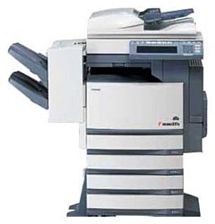
Toshiba e-Studio 451c
Рейтинг

 Снят с производства
Тип устройства
МФУ
Технология печати
лазерная
Макс. формат
A3
Скорость печати
A4
45
Цветность печати
цветная
Общие характеристики |
|
|---|---|
Тип устройства |
МФУ |
Факс |
|
Печать фотографий |
|
Телефон |
|
Копир |
|
Сканер |
|
Технология печати |
лазерная |
Макс. формат |
A3 |
Тип |
лазерный/светодиодный |
Цветность печати |
цветная |
Размещение |
настольный |
Принтер |
|
Двусторонняя печать |
|
Пигментные чернила |
|
Печать без полей |
|
Время разогрева |
40 |
Макс, разрешение для ч/б печати |
|
| По X | 1 200 |
| По Y | 600 |
| По X | 2 400 |
Скорость ч/б печати |
|
| A4 | 45 |
Копир |
|
Время выхода первой копии |
7 |
Макс, количество копий за цикл |
999 |
Шаг масштабирования |
0,01 |
Значение масштаба |
|
| Минимальное | 0,25 |
| Максимальное | 4 |
Макс, разрешение (ч/б) |
|
| По Y | 600 |
| По X | 600 |
Скорость цветного копирования |
|
| A4 | 11 |
Сканер |
|
Оттенки серого |
256 |
Макс. формат оригинала |
A3 |
Тип сканера |
планшетный/протяжный |
Макс, размер сканирования |
|
| По Y | 432 |
| По X | 297 |
Разрешение сканера |
|
| По Х | 600 |
Скорость сканирования |
|
| Цветн, | 40 |
| Ч/б | 50 |
Расходные материалы |
|
Количество картриджей |
4 |
Ресурс девелопера |
120 000 |
Печать на: |
|
| Матовой бумаге |
|
| Этикетках |
|
| Пленках |
|
| Карточках |
|
| Глянцевой бумаге |
|
| Конвертах |
|
| Рулоне |
|
| CD/DVD |
|
| Фотобумаге |
|
Плотность бумаги |
|
| Максимальная | 209 |
| Минимальная | 64 |
Факс |
|
Цветной |
|
Телефон |
|
Проводная трубка |
|
Беспроводная трубка |
|
АОН |
|
Caller ID |
|
Спикерфон |
|
Стандарт DECT |
|
Автоответчик |
|
Языки управления |
|
| PPDS |
|
| PCL 5e |
|
| PostScript 2 |
|
|
|
|
| PostScript 3 |
|
| PostScript |
|
| PCL 5c |
|
| PCL 6 |
|
Лотки |
|
Подача бумаги |
|
| Стандартная | 1 200 |
Вывод бумаги |
|
| Стандартный | 550 |
Финишер |
|
Сортировка со сдвигом |
|
Сортер |
|
Интерфейсы |
|
Wi-Fi |
|
Bluetooth |
|
LPT |
|
Инфракрасный порт |
|
FireWire (IEEE 1394) |
|
RS-232 |
|
Устройство для чтения карт памяти |
|
USB |
|
Ethernet (RJ-45) |
|
Версия USB |
2,0 |
Память/Процессор |
|
Макс, объем памяти |
512 |
Емкость жесткого диска |
80 |
Объем памяти |
256 |
Дополнительная информация |
|
Поддержка ОС |
|
| Windows |
|
Потребляемая мощность |
|
| При работе | 1 700 |
Габариты |
|
Вес |
113 |
Глубина |
660 |
Ширина |
718 |
Высота |
739 |
Модули
ALIGNING-1-ASM
PLATEN-ASM
FUSER-1-ASM
FEEDER-1-ASM
REVOLVER-UNIT-1-ASM
BYPASS-FEEDER-2-ASM
COVER-2-ASM
BYPASS-FEEDER-1-ASM
DRUM-DRIVE-ASM
BASE-FRAME-ASM
CASE-LGC-ASM
CLEANER-ASM
REAR-FRAME-ASM
OPTICAL-DRIVE-ASM
BYPASS-ASM
DEVELOPER-YMC-ASM
TONER-1-ASM
CASE-SYS-ASM
OPTICAL-FRAME-ASM
FEEDER-2-ASM
TR2-UNIT-1-ASM
POWER-SUPPLY-ASM
TR2-UNIT-2-ASM
TONER-2-ASM
LASER-OPTICAL-UNIT-ASM
TRANSPORT-BELT-UNIT-1-ASM
ADU-ASM
MAIN-CHARGER-ASM
FUSER-4-ASM
FEED-DRIVE-ASM
CRG-2-ASM
REPLACE UNIT
BELT-CLEAN-UNIT-ASM
FUSER-3-ASM
REVOLVER-UNIT-2-ASM
FUSER-2-ASM
CONTROL-PANEL-ASM
DRAWER-ASM
FRONT-FRAME-ASM
TRANSPORT-BELT-UNIT-2-ASM
ALIGNING-2-ASM
DEVELOPER-BLACK-ASM
CRG-1-ASM
DEV-DRIVE-ASM
COVER-1-ASM
Детали FEEDER-1-ASM

| Деталь: | ASYS-GUIDE-RGST-L |
| Парткод: | 6LA37720000 |
| Деталь: | ASYS-GUIDE-RGST-R |
| Парткод: | 6LE46204000 |
| Деталь: | ACTR-REG |
| Парткод: | 6LA37627000 |
| Деталь: | ACTR-MID |
| Парткод: | 6LA37629000 |
| Деталь: | HLDR-REG-SENSOR |
| Парткод: | 6LA37626000 |
| Деталь: | GP1A73ARJ00F |
| Парткод: | C0-10813000 |
| Деталь: | SPG-ACT |
| Парткод: | 6LA37634000 |
| Деталь: | HRNS-TBNA-350 |
| Парткод: | 6LA41620000 |
| Деталь: | S/TPP/FH/FEXM-3X8-NI |
| Парткод: | X0-02247000 |
| Деталь: | MYLAR-SW-RGST-2 |
| Парткод: | 44201543000 |
| Деталь: | P/PRL/AH7-2X12-SS |
| Парткод: | X0-01526000 |
| Деталь: | GEAR-10S020-08 |
| Парткод: | 4401964660 |
| Деталь: | BUSH-8X12X11S-POM |
| Парткод: | 6LA37644000 |
| Деталь: | STOP-RING-8 |
| Парткод: | 4400336190 |
| Деталь: | ROLLER-RGST-R |
| Парткод: | 6LA37709000 |
| Деталь: | BUSH-8X12X8F |
| Парткод: | 6LA65698000 |
| Деталь: | SPG-E-RGST-MC-FRT |
| Парткод: | 6LA37704000 |
| Деталь: | RLR-MID-350 |
| Парткод: | 6LA37706000 |
| Деталь: | COV_IQ_MAIN |
| Парткод: | 6LA34035000 |
| Деталь: | SHUT-IQ |
| Парткод: | 6LA34037000 |
| Деталь: | SOL_IQ |
| Парткод: | 6LA34003000 |
| Деталь: | SPG-E-5R3XR3X18R14 |
| Парткод: | 6LA34004000 |
| Деталь: | HRNS-FED1-350 |
| Парткод: | 6LA41539000 |
| Деталь: | SNSR-CTD-410 |
| Парткод: | 6LE48700000 |
| Деталь: | LWS-0711Z |
| Парткод: | F0-00736000 |
| Деталь: | UAMS-05-0 |
| Парткод: | F0-01048000 |
| Деталь: | BRKT-LG-SW-350 |
| Парткод: | 6LA35582000 |
| Деталь: | HLDR-MID-ROLLER |
| Парткод: | 6LA37640000 |
| Деталь: | GUIDE-MIDDLE-410 |
| Парткод: | 6LE46410000 |
| Деталь: | S/TPS/BID-3X12-ZU3 |
| Парткод: | X0-02072000 |
| Деталь: | MYLAR-GUIDE-RGST-FRT |
| Парткод: | 6LA37691000 |
| Деталь: | ROLLER-RGST-L |
| Парткод: | 6LE46207000 |
| Деталь: | MYLAR-GUIDE-RGST-RER |
| Парткод: | 6LA37692000 |
| Деталь: | HLDR-ERTH-RGST |
| Парткод: | 6LA37611000 |
| Деталь: | SPG-F-RGST-R |
| Парткод: | 6LA37612000 |
| Деталь: | SPG-F-RGST-L |
| Парткод: | 6LA37613000 |
| Деталь: | ASYS-ERZV10D821-350 |
| Парткод: | 6LA37732000 |
| Деталь: | MYLAR-RGST-L |
| Парткод: | 6LA37658000 |
| Деталь: | MYLAR-RGST-R |
| Парткод: | 6LA37659000 |
| Деталь: | KNOB-RGST-350 |
| Парткод: | 6LA41229000 |
| Деталь: | SCREW-LOCK-ARM |
| Парткод: | 6LA37669000 |
| Деталь: | SPG-E-RGST-MC-RER |
| Парткод: | 6LA37705000 |
| Деталь: | ES-0505 |
| Парткод: | F0-00120000 |
| Деталь: | GEAR-10S20-08-N |
| Парткод: | 6LA37714000 |
| Деталь: | BRUSH-RH-6H |
| Парткод: | 6LA37721000 |
| Деталь: | SHEET-GUARD-RGST |
| Парткод: | 6LA37728000 |
| Деталь: | RR/E-7-SS |
| Парткод: | X0-00968000 |
| Деталь: | S/PAN/SWWP-M2.6X6-NI |
| Парткод: | X0-02103000 |
| Деталь: | S/TPP/PAN-3X6-NI |
| Парткод: | X0-00595000 |
| Деталь: | S/BID-M3X8-BSNI |
| Парткод: | X0-01991000 |
| Деталь: | S/TPS/FHEXM-4X8-ZU3 |
| Парткод: | X0-02243000 |
| Деталь: | MSB-1207 |
| Парткод: | F0-01250000 |
| Деталь: | ASYS-GLASS-ADF-350 |
| Парткод: | 6LA39804000 |
| Деталь: | SPL-GLASS-ADF |
| Парткод: | 6LA39841000 |
| Деталь: | MYLAR-TAPE-FRT |
| Парткод: | 6LA39843000 |
| Деталь: | SEAL-COLOR-TP-L-R2 |
| Парткод: | 6LA39889000 |
| Деталь: | SHEET-GEL-13-4 |
| Парткод: | 6LA39375000 |
| Деталь: | MYLAR-SPL-GLASS-ADF |
| Парткод: | 6LA39842000 |
| Деталь: | S/TPS/FHEXM-3X6-ZU3 |
| Парткод: | X0-02238000 |
| Деталь: | ASYS-GLASS-410A |
| Парткод: | 6LE46350000 |
| Деталь: | ASYS-GLASS-410L |
| Парткод: | 6LE46350100 |
| Деталь: | ASYS-GLASS-410K |
| Парткод: | 6LE46350200 |
| Деталь: | BRUSH-FUS-PR |
| Парткод: | 6LE45616000 |
| Деталь: | BRKT-ARM-F |
| Парткод: | 6LA36217000 |
| Деталь: | BRKT-ARM-R |
| Парткод: | 6LA36218000 |
| Деталь: | COLLAR-BRG-PS |
| Парткод: | 6LA36294000 |
| Деталь: | HR-281C-L |
| Парткод: | 6LE19660000 |
| Деталь: | 6803ZZS1C4KZ |
| Парткод: | F0-01383000 |
| Деталь: | BRKT-SPL-R |
| Парткод: | 6LA36170000 |
| Деталь: | BRKT-SCR-PR |
| Парткод: | 6LA36292000 |
| Деталь: | BRKT-SPL |
| Парткод: | 6LA36169000 |
| Деталь: | BUSH-6 |
| Парткод: | 4401759090 |
| Деталь: | GEAR-10S37-10S34-8 |
| Парткод: | 6LA36282000 |
| Деталь: | GEAR-IDLE-15-23 |
| Парткод: | 44203038000 |
| Деталь: | GEAR-10S18-10S25-6 |
| Парткод: | 6LA36329000 |
| Деталь: | ASYS-COV-FUS-PR |
| Парткод: | 6LE45641000 |
| Деталь: | SPG-E-FUS-BELT |
| Парткод: | 6LA36241000 |
| Деталь: | SPG-ARM-FUSER |
| Парткод: | 6LA36363000 |
| Деталь: | SCREW-M3-FUS |
| Парткод: | 6LA36227000 |
| Деталь: | SCREW-BKT-DEV |
| Парткод: | 6LA08937000 |
| Деталь: | SCREW-FUSER-M4B-N |
| Парткод: | 6LA36437000 |
| Деталь: | SPG-E-SCRAPER |
| Парткод: | 6LA34929000 |
| Деталь: | STUD-IH-R |
| Парткод: | 6LA36201000 |
| Деталь: | STUD-FUS-STAY |
| Парткод: | 6LA36238000 |
| Деталь: | COV-GER-R |
| Парткод: | 6LA36348000 |
| Деталь: | COV-GUIDE-RTN-L |
| Парткод: | 6LE45640000 |
| Деталь: | SCRAPR-FUS-350 |
| Парткод: | 6LA36256000 |
| Деталь: | PLATE-ENT-HR |
| Парткод: | 6LA36274000 |
| Деталь: | PLATE-ENT-PR |
| Парткод: | 6LA36378000 |
| Деталь: | GEAR-SEP-IDLE-1 |
| Парткод: | 44203023000 |
| Деталь: | GUIDE-ENT-PR |
| Парткод: | 6LA36128000 |
| Деталь: | BUSH-6-GCB |
| Парткод: | 4407734980 |
| Деталь: | SPG-BRG-RL-PS |
| Парткод: | 6LA36302000 |
| Деталь: | LBL-FUS-4 |
| Парткод: | 6LA36408000 |
| Деталь: | LEVER-ARM-FUSER |
| Парткод: | 6LA36124000 |
| Деталь: | SHAFT-ARM-FUSER |
| Парткод: | 6LA36150000 |
| Деталь: | LEVER-FUS-ARM-H |
| Парткод: | 6LA36278000 |
| Деталь: | SPG-C-7R4XR4X20R |
| Парткод: | 6LA36243000 |
| Деталь: | CAM-ARM-FUSER |
| Парткод: | 6LA36118000 |
| Деталь: | SHAFT-LEVER-ARM |
| Парткод: | 6LA36119000 |
| Деталь: | ARM-FUSER-F-S |
| Парткод: | 6LA36291000 |
| Деталь: | ARM-FUSER-R-S |
| Парткод: | 6LA36290000 |
| Деталь: | SHEET-FUS-HND |
| Парткод: | 6LA36454000 |
| Деталь: | guide-exit-rtn |
| Парткод: | 6LA34906000 |
| Деталь: | gate-fuser |
| Парткод: | 44202991000 |
| Деталь: | SHAFT-GATE-L |
| Парткод: | 6LA36297000 |
| Деталь: | SPL-GUIDE-R-350 |
| Парткод: | 6LA34935000 |
| Деталь: | SHAFT-IDLE-CL |
| Парткод: | 6LA36330000 |
| Деталь: | GEAR-10S18-6 |
| Парткод: | 6LA34921000 |
| Деталь: | SPG-C-4R46XR15X17R3 |
| Парткод: | 6LA36353000 |
| Деталь: | GATE-FUSER-SEN |
| Парткод: | 6LA36327000 |
| Деталь: | SHEET-SNSR-EXIT |
| Парткод: | 6LE45633000 |
| Деталь: | BRKT-COV-HNS-R-410 |
| Парткод: | 6LE45634000 |
| Деталь: | S/TPS/BID-3X10-ZU3 |
| Парткод: | X0-02071000 |
| Деталь: | SNSR-HOME-141 |
| Парткод: | 6LE69562000 |
| Деталь: | UAMS-05L-0-46 |
| Парткод: | F0-00270000 |
| Деталь: | S/FHEXM-M3X6-NI |
| Парткод: | X0-02230000 |
| Деталь: | S/TPS/FHEXM-3X6-ZU3 |
| Парткод: | X0-02238000 |
| Деталь: | RR/E-7-SS |
| Парткод: | X0-00968000 |
| Деталь: | S/BID-M3X8-NI |
| Парткод: | X0-00434000 |
| Деталь: | RR/E-5-SS |
| Парткод: | X0-00966000 |
| Деталь: | S/TPS/BID-3X6-ZU3 |
| Парткод: | X0-02069000 |
| Деталь: | RR/E-1.5-SS |
| Парткод: | X0-00973000 |
| Деталь: | P/SPW/AW-2X10-SS |
| Парткод: | X0-01009000 |
| Деталь: | PLWS-1-46B |
| Парткод: | F0-00032000 |
| Деталь: | SHEET-FUS-HOT |
| Парткод: | 6LA36306000 |
| Деталь: | SHEET-FUS-HOT-TWD |
| Парткод: | 6LA48560000 |
| Деталь: | BRKT-ROL-SEP |
| Парткод: | 6LA47898000 |
| Деталь: | guide-p-sep |
| Парткод: | 41318623000 |
| Деталь: | hldr-sep-rol-dm |
| Парткод: | 44201805000 |
| Деталь: | LEVER-RLR-PICK |
| Парткод: | 6LA47910000 |
| Деталь: | K-ROLL-SPT |
| Парткод: | 41304047100 |
| Деталь: | ARBOR-SPT-F |
| Парткод: | 4401964360 |
| Деталь: | ARBOR-SPT-R |
| Парткод: | 4401964270 |
| Деталь: | SFT-SEP-AT |
| Парткод: | 41304506000 |
| Деталь: | SPR-1.0-15.60RF |
| Парткод: | 44201817000 |
| Деталь: | SPC055-045-01525 |
| Парткод: | 6LA47909000 |
| Деталь: | cov-spe/arbor |
| Парткод: | 44201773000 |
| Деталь: | CHIP-HLDR-SEP |
| Парткод: | 41319491000 |
| Деталь: | GUIDE-P-FEED |
| Парткод: | 6LA47908000 |
| Деталь: | ACTR-EMPTY-PPR |
| Парткод: | 41306012000 |
| Деталь: | ARM-FEED-UNIT |
| Парткод: | 41318603000 |
| Деталь: | SFT-DRV-PICK |
| Парткод: | 41318604000 |
| Деталь: | ARM-RLR-PICK |
| Парткод: | 41306011000 |
| Деталь: | PLY/T-PICK-20 |
| Парткод: | 41306002000 |
| Деталь: | STOP-RING-6-5 |
| Парткод: | 4407972860 |
| Деталь: | ROLLER-PICK-AT |
| Парткод: | 41306719000 |
| Деталь: | CLUTCH-6-08L2 |
| Парткод: | 4406584800 |
| Деталь: | PLY-20-2M |
| Парткод: | 4402231780 |
| Деталь: | SFT-ROL-FEED |
| Парткод: | 41304508000 |
| Деталь: | K-ROLL-FEED |
| Парткод: | 6LE69833000 |
| Деталь: | BUSH-6-POM |
| Парткод: | 44201492000 |
| Деталь: | PLY/T-20-ROL-2G |
| Парткод: | 41306274000 |
| Деталь: | lev-rol-sep-dm |
| Парткод: | 44201810000 |
| Деталь: | ASYS-BRKT-CLT |
| Парткод: | 6LA47895000 |
| Деталь: | CLUTCH-33C-6-CW-GEAR |
| Парткод: | 6LA31944000 |
| Деталь: | GP1A73ARJ00F |
| Парткод: | C0-10813000 |
| Деталь: | BUSH-6-GCB |
| Парткод: | 4407734980 |
| Деталь: | BLT/T-194-2GT-2 |
| Парткод: | 41306504000 |
| Деталь: | BLT/T-124-2GT-2 |
| Парткод: | 41306502000 |
| Деталь: | KI-100M |
| Парткод: | F0-01470000 |
| Деталь: | SPR-LVR-PICK |
| Парткод: | 41305501000 |
| Деталь: | HRNS-PFP-FED-UNIT-576 |
| Парткод: | 6LA41754000 |
| Деталь: | ASYS-BRKT-FEED-UNIT |
| Парткод: | 6LA47892000 |
| Деталь: | S/TPP/FH/FEXM-3X8-NI |
| Парткод: | X0-02247000 |
| Деталь: | P/PRL/AH7-2X8-SS |
| Парткод: | X0-00979000 |
| Деталь: | RR/E-5-SS |
| Парткод: | X0-00966000 |
| Деталь: | 54702-1219 |
| Парткод: | E0-08732000 |
| Деталь: | S/SET/K-M3X4-B |
| Парткод: | X0-00730000 |
| Деталь: | LWS-1S |
| Парткод: | F0-00235000 |
| Деталь: | S/TPS/FHEXM-3X6-ZU3 |
| Парткод: | X0-02238000 |
| Деталь: | EDS-0607M |
| Парткод: | F0-00671000 |
| Деталь: | BUSH-8X12X5R5F |
| Парткод: | 6LA65697000 |
| Деталь: | SHAFT-LIFT-F2 |
| Парткод: | 6LE43300000 |
| Деталь: | SHAFT-LIFT-R2 |
| Парткод: | 6LE43301000 |
| Деталь: | GEAR-08H19-8-BLK |
| Парткод: | 6LA29842000 |
| Деталь: | STUD-GEAR-IDLE |
| Парткод: | 6LE43302000 |
| Деталь: | RR/E-7-SS |
| Парткод: | X0-00968000 |
| Деталь: | SHAFT-CAM-LIFT |
| Парткод: | 6LA29833000 |
| Деталь: | CAM-FRT-LIFT |
| Парткод: | 6LA29946000 |
| Деталь: | CAM-RER-LIFT |
| Парткод: | 6LA29832000 |
| Деталь: | ACTR-CAM-LIFT |
| Парткод: | 6LA29830000 |
| Деталь: | BUSH-6-GCB |
| Парткод: | 4407734980 |
| Деталь: | ROCK-RTNR-DEV-F41X |
| Парткод: | 6LE43623000 |
| Деталь: | CHAS-LIFT-410 |
| Парткод: | 6LE43303000 |
| Деталь: | GEAR-08H20 |
| Парткод: | 6LE43304000 |
| Деталь: | BUSH-ROCK-RTNR-DEV-F41X |
| Парткод: | 6LE43624000 |
| Деталь: | GUIDE-FRAME-LIFT-R |
| Парткод: | 6LE45004000 |
| Деталь: | GP1A73ARJ00F |
| Парткод: | C0-10813000 |
| Деталь: | MYLAR-CHAS-LIFT-410 |
| Парткод: | 6LE43305000 |
| Деталь: | S/TPS/FHEXM-3X6-ZU3 |
| Парткод: | X0-02238000 |
| Деталь: | COVER-SNSR-LIFT |
| Парткод: | 6LA29902000 |
| Деталь: | SPG-L-DETENT-C1 |
| Парткод: | 6LA29945000 |
| Деталь: | SPG-E-8R5XR9X30R5-LIFT |
| Парткод: | 6LA29847000 |
| Деталь: | STOP RING |
| Парткод: | 41306265000 |
| Деталь: | HRNS-KDVP2-410 |
| Парткод: | 6LE48028000 |
| Деталь: | SPG-ROCK-DEV-A-F41F |
| Парткод: | 6LE43622000 |
| Деталь: | STOP-RING-6-5 |
| Парткод: | 4407972860 |
| Деталь: | GEAR-10S27-6 |
| Парткод: | 6LA31912000 |
| Деталь: | S/TPS/FHEXM-4X8-ZU3 |
| Парткод: | X0-02243000 |
| Деталь: | SPG-E-8R5XR9X32R3-LIFT |
| Парткод: | 6LA29871000 |
| Деталь: | S/FHEXM-M4X8-NI |
| Парткод: | X0-02235000 |
| Деталь: | P/PRL/BH7-2X14-SS |
| Парткод: | X0-00990000 |
| Деталь: | RR/E-5-SS |
| Парткод: | X0-00966000 |
| Деталь: | ES-0505 |
| Парткод: | F0-00120000 |
| Деталь: | LWS-0711Z |
| Парткод: | F0-00736000 |
| Деталь: | T18S |
| Парткод: | F0-00017000 |
| Деталь: | S/PAN-M3X4-NI |
| Парткод: | X0-02113000 |
| Деталь: | RR/E-4-SS |
| Парткод: | X0-00965000 |
| Деталь: | COV-HEAT-DRUM |
| Парткод: | 6LA29940000 |
| Деталь: | HEATR-DRUM-350X |
| Парткод: | 6LA41635000 |
| Деталь: | HEATR-DRUM-350X |
| Парткод: | 6LA41635100 |
| Деталь: | THRMST-CS-7L |
| Парткод: | 6LE09486000 |
| Деталь: | ASYS-FRAME-BYPASS-410 |
| Парткод: | 6LE40413000 |
| Деталь: | SPL-IDLR-TR-BYPS |
| Парткод: | 6LA28967000 |
| Деталь: | SHAFT-IDLR-TR-BYPS |
| Парткод: | 6LA28966000 |
| Деталь: | IDLER-TR-BYPASS-K |
| Парткод: | 6LE40416000 |
| Деталь: | GP1A73ARJ00F |
| Парткод: | C0-10813000 |
| Деталь: | ACTUATOR-BYP |
| Парткод: | 6LE40422000 |
| Деталь: | SPG-T-SNSR-LOW-T |
| Парткод: | 6LA28960000 |
| Деталь: | BRKT-ACT-BYP |
| Парткод: | 6LA28952000 |
| Деталь: | BRKT-BYPASS-FRT |
| Парткод: | 6LA29032000 |
| Деталь: | GUIDE-BYPASS-U |
| Парткод: | 6LE40440000 |
| Деталь: | SOL-SFB-340 |
| Парткод: | 6LA15259000 |
| Деталь: | LEVER-PICK |
| Парткод: | 6LA28767000 |
| Деталь: | STUD-LVR-PIC-BP |
| Парткод: | 6LE40435000 |
| Деталь: | SPG-E-6R5XR7X28R5L |
| Парткод: | 6LA28769000 |
| Деталь: | STAY-BYPASS-U |
| Парткод: | 6LA28827000 |
| Деталь: | ASYS-COVER-BYPASS-U |
| Парткод: | 6LE40442000 |
| Деталь: | ACTR-EMP-SW-BYP |
| Парткод: | 6LA28768000 |
| Деталь: | ASYS-BRKT-STOPPER |
| Парткод: | 6LA28823000 |
| Деталь: | STPR-BYP-F-350 |
| Парткод: | 6LA28821000 |
| Деталь: | ARM-STOPPER |
| Парткод: | 4401965270 |
| Деталь: | LEVER-STOPPER-F |
| Парткод: | 4401965250 |
| Деталь: | STPR-BYP-R-350 |
| Парткод: | 6LA28822000 |
| Деталь: | LEVER-STOPPER-R |
| Парткод: | 4401965260 |
| Деталь: | PLATE-ARM-PICK |
| Парткод: | 6LA28819000 |
| Деталь: | BLT-SY-138-2GT-2.8 |
| Парткод: | 6LA28835000 |
| Деталь: | K-ROLL-PICK-SFB |
| Парткод: | 44218398000 |
| Деталь: | SFT-ROL-PIC-BYP-350 |
| Парткод: | 6LE40436000 |
| Деталь: | SHAFT-ROL-FEED-BYPS |
| Парткод: | 6LA28807000 |
| Деталь: | GEAR-06S-027-06 |
| Парткод: | 6LA28811000 |
| Деталь: | CLUTCH-6-08L2 |
| Парткод: | 4406584800 |
| Деталь: | ARM-PICK-350 |
| Парткод: | 6LA28756000 |
| Деталь: | WEIGHT-PICK-BYP-LOW |
| Парткод: | 6LA28832000 |
| Деталь: | WEIGHT-PICK-BYP-UP |
| Парткод: | 6LA28834000 |
| Деталь: | SPL-ROL-FEED-BYP |
| Парткод: | 6LA28817000 |
| Деталь: | CUSHION-PAD |
| Парткод: | 6LA28758000 |
| Деталь: | PLY/T-2GT020-06 |
| Парткод: | 4401966400 |
| Деталь: | K-RLR-FEED-SFB |
| Парткод: | 44218389000 |
| Деталь: | STOP-RING-6-5 |
| Парткод: | 4407972860 |
| Деталь: | CPG-DRVN-BYP-350 |
| Парткод: | 6LA28812000 |
| Деталь: | ROLLER-TR-BYPASS-18.5 |
| Парткод: | 6LE40425000 |
| Деталь: | STUD-G032-BYPS |
| Парткод: | 6LE40439000 |
| Деталь: | GEAR-06S-032-06 |
| Парткод: | 44201789000 |
| Деталь: | HRNS-SFB-410 |
| Парткод: | 6LE48072000 |
| Деталь: | BUSH-6-GCB |
| Парткод: | 4407734980 |
| Деталь: | SCREW-WEIGHT-3*6 |
| Парткод: | 6LE40407000 |
| Деталь: | WEIGHT-PICK-BYP-T |
| Парткод: | 6LE40412000 |
| Деталь: | WEIGHT-PICK-BYP-MID |
| Парткод: | 6LA28833000 |
| Деталь: | HRNS-SFB-PIS-360 |
| Парткод: | 6LA71421000 |
| Деталь: | LBL-BYPS-CAUSION |
| Парткод: | 6LA29004000 |
| Деталь: | SPL-IDLR-TR-BYP-36-2 |
| Парткод: | 6LE40417000 |
| Деталь: | P/PRL/AH7-2X8-SS |
| Парткод: | X0-00979000 |
| Деталь: | S/CTS-M3X8-NI |
| Парткод: | X0-02011000 |
| Деталь: | S/TPP/FH/FEXM-3X8-NI |
| Парткод: | X0-02247000 |
| Деталь: | RR/E-3-SS |
| Парткод: | X0-00964000 |
| Деталь: | RR/E-5-SS |
| Парткод: | X0-00966000 |
| Деталь: | COVER-TP-RER-410 |
| Парткод: | 6LE40908000 |
| Деталь: | S/TPS/FHEXM-4X8-ZU3 |
| Парткод: | X0-02243000 |
| Деталь: | COVER-TP-FRT-410 |
| Парткод: | 6LE40937000 |
| Деталь: | COVER-RGT-LWR |
| Парткод: | 6LE40926000 |
| Деталь: | COVER-IH |
| Парткод: | 6LE40931000 |
| Деталь: | COVER-HINGE-RER-410 |
| Парткод: | 6LE40964000 |
| Деталь: | COVER-REAR-F410 |
| Парткод: | 6LE40969000 |
| Деталь: | COVER-DF-CONECT |
| Парткод: | 6LE40929000 |
| Деталь: | POCKET-MANUAL |
| Парткод: | 6LE40940000 |
| Деталь: | S/FHEXM-M4X8-NI |
| Парткод: | X0-02235000 |
| Деталь: | LID-SCREW |
| Парткод: | 6LA29556000 |
| Деталь: | FILTER-DUCT-RER-350 |
| Парткод: | 6LA29564000 |
| Деталь: | PLATE-TP-RER-FAN-350 |
| Парткод: | 6LA29563000 |
| Деталь: | COV-REAR-CASE-SYS |
| Парткод: | 6LE40918000 |
| Деталь: | COVER-GEL-RER |
| Парткод: | 6LE40910000 |
| Деталь: | S/TPP/FH/FEXM-3X6-NI |
| Парткод: | X0-02246000 |
| Деталь: | LBL-PM |
| Парткод: | 6LA47613000 |
| Деталь: | LBL-LASER |
| Парткод: | 6LA47529000 |
| Деталь: | LBL-LASER-TWD |
| Парткод: | 6LA48505000 |
| Деталь: | LBL-LASER-C |
| Парткод: | 6LA56226000 |
| Деталь: | LBL-LASER-KR |
| Парткод: | 6LA15055000 |
| Деталь: | LABEL-FCC-18 |
| Парткод: | 6LA15839000 |
| Деталь: | LABEL-CANADA-A |
| Парткод: | 4408860880 |
| Деталь: | LABEL-CHINA |
| Парткод: | 4400685400 |
| Деталь: | LBL-SERVICE-45 |
| Парткод: | 44204604000 |
| Деталь: | LBL-SERVICE-45-TWD |
| Парткод: | 6LA48504000 |
| Деталь: | LBL-SERVICE-45C |
| Парткод: | 6LA56227000 |
| Деталь: | LBL-SERVICE-KR |
| Парткод: | 6LA15072000 |
| Деталь: | ASYS-ROLL-SPT-L30 |
| Парткод: | 6LA28899000 |
| Деталь: | ARBOR-SPT-BYP |
| Парткод: | 6LA28863000 |
| Деталь: | SPG-1.0-0.15-65-13L |
| Парткод: | 6LA28865000 |
| Деталь: | SHAFT-ROL-SPT |
| Парткод: | 6LE40437000 |
| Деталь: | LEVER-SPT-F |
| Парткод: | 6LA28921000 |
| Деталь: | LEVER-SPT-R |
| Парткод: | 6LA28922000 |
| Деталь: | SPG-E-6XR6X91R7R |
| Парткод: | 6LA28840000 |
| Деталь: | STAY-SPT-BYP-350 |
| Парткод: | 6LA28896000 |
| Деталь: | ASYS-BRKT-LVR-SPT |
| Парткод: | 6LA28857000 |
| Деталь: | COVER-SPE-ARBOR-17 |
| Парткод: | 6LA28861000 |
| Деталь: | HOLDER-ROL-SPT-BYP |
| Парткод: | 6LA28862000 |
| Деталь: | SCR-M3X6BISR-NI |
| Парткод: | 6LA08935000 |
| Деталь: | ASYS-BRKT-DRV-BYP-2 |
| Парткод: | 6LE40415000 |
| Деталь: | ASYS-ARM-JOINT-BYPS |
| Парткод: | 6LA28755000 |
| Деталь: | GEAR-10S023-06-2 |
| Парткод: | 6LE40421000 |
| Деталь: | GEAR-1-S021-06 |
| Парткод: | 6LA28932000 |
| Деталь: | GEAR-10S022-10S027-SK |
| Парткод: | 6LE40420000 |
| Деталь: | CLUTCH-G28-08D-30A |
| Парткод: | 6LE40813000 |
| Деталь: | ASYS-SHAFT-BYPS-410 |
| Парткод: | 6LE40445000 |
| Деталь: | CPG-DRV-BYP-350 |
| Парткод: | 6LA28915000 |
| Деталь: | BUSH-8X12X8F |
| Парткод: | 6LA65698000 |
| Деталь: | STOP-RING-6-5 |
| Парткод: | 4407972860 |
| Деталь: | ROL-BYPS-DRV |
| Парткод: | 6LA28931000 |
| Деталь: | BUSH-6-GCB |
| Парткод: | 4407734980 |
| Деталь: | RR/E-5-SS |
| Парткод: | X0-00966000 |
| Деталь: | RR/E-4-SS |
| Парткод: | X0-00965000 |
| Деталь: | S/TPS/FHEXM-3X6-ZU3 |
| Парткод: | X0-02238000 |
| Деталь: | ES-0505 |
| Парткод: | F0-00120000 |
| Деталь: | S/FHEXM-M3X6-NI |
| Парткод: | X0-02230000 |
| Деталь: | RR/E-7-SS |
| Парткод: | X0-00968000 |
| Деталь: | S/TPP/BID-3X8-NI |
| Парткод: | X0-01989000 |
| Деталь: | S/TPP/FH/FEXM-3X8-NI |
| Парткод: | X0-02247000 |
| Деталь: | ASYS-PLT-DRV-MAIN-FL |
| Парткод: | 6LE43917000 |
| Деталь: | GEAR-08S15_P2GT-53 |
| Парткод: | 6LA32534000 |
| Деталь: | SPG-C-DRV-TBU |
| Парткод: | 6LE43944000 |
| Деталь: | COLAR-COP_TEN |
| Парткод: | 6LE43905000 |
| Деталь: | LNR-1680HHRP0P15LY13 |
| Парткод: | F0-01390000 |
| Деталь: | CPL-DRV-IN |
| Парткод: | 6LE43943000 |
| Деталь: | GEAR-04H150-04H84-158 |
| Парткод: | 6LE43948000 |
| Деталь: | ASYS-G05H80_G04H72-BRG |
| Парткод: | 6LE43946000 |
| Деталь: | ASYS-DRM-SF-HUSNG-FL |
| Парткод: | 6LE43930000 |
| Деталь: | GEAR-10S32-08 |
| Парткод: | 6LE43906000 |
| Деталь: | GEAR-10S27_10S20-6 |
| Парткод: | 6LA32532000 |
| Деталь: | GEAR-10S40_10S23-06 |
| Парткод: | 6LA32519000 |
| Деталь: | GEAR-08S47-350 |
| Парткод: | 6LA32642000 |
| Деталь: | GEAR-21-45-350 |
| Парткод: | 6LA32643000 |
| Деталь: | SPACER-CPL-DRV-IN |
| Парткод: | 6LE43954000 |
| Деталь: | SPF-DRUM-EARTH |
| Парткод: | 6LE43926000 |
| Деталь: | MOTR_D-MAIN-410 |
| Парткод: | 6LE43950000 |
| Деталь: | BRKT-GEAR-COV |
| Парткод: | 6LE43927000 |
| Деталь: | GEAR-08S31-06-DCL |
| Парткод: | 6LA32641000 |
| Деталь: | SFT-DRV-AUG-CLD |
| Парткод: | 6LE43934000 |
| Деталь: | BUSH-6-GCB |
| Парткод: | 4407734980 |
| Деталь: | GEAR-10S19-06 |
| Парткод: | 6LA32522000 |
| Деталь: | STOP-RING-6-5 |
| Парткод: | 4407972860 |
| Деталь: | BLT.SY-164-2GT-6 |
| Парткод: | 6LA32645000 |
| Деталь: | MOTR_D-AUG-410 |
| Парткод: | 6LE43937000 |
| Деталь: | S/TPS/FHEXM-3X8-ZU3 |
| Парткод: | X0-02239000 |
| Деталь: | S/TPS/FHEXM-3X6-ZU3 |
| Парткод: | X0-02238000 |
| Деталь: | FILTER-OZ-SPB-600 |
| Парткод: | 6LA34329000 |
| Деталь: | S/TPS/FHEXM-4X8-ZU3 |
| Парткод: | X0-02243000 |
| Деталь: | S/TPS/FHEXM-4X12-ZU3 |
| Парткод: | X0-02245000 |
| Деталь: | S/TPP/FHEXM-4X12-NI |
| Парткод: | X0-02253000 |
| Деталь: | ASYS-BRKT-AUG-MTR |
| Парткод: | 6LE43913000 |
| Деталь: | FAN-D-8025-350NH |
| Парткод: | 6LA34342000 |
| Деталь: | DUCT-OZN-1 |
| Парткод: | 6LE43900000 |
| Деталь: | DUCT-OZN-2 |
| Парткод: | 6LE43901000 |
| Деталь: | SFT-CPL-DRV-TBU-FL |
| Парткод: | 6LE43945000 |
| Деталь: | SEAL-DUCT-OZ1-F410 |
| Парткод: | 6LE44804000 |
| Деталь: | SEAL-DUCT-OZ2-F410 |
| Парткод: | 6LE44805000 |
| Деталь: | P/PRL/AH7-3X10-SS |
| Парткод: | X0-01168000 |
| Деталь: | UAMS-05-0 |
| Парткод: | F0-01048000 |
| Деталь: | RR/E-7-SS |
| Парткод: | X0-00968000 |
| Деталь: | RSG-100 |
| Парткод: | F0-00257000 |
| Деталь: | RR/E-5-SS |
| Парткод: | X0-00966000 |
| Деталь: | S/PAN-M2.6X4-NC |
| Парткод: | X0-01670000 |
| Деталь: | S/PAN/SWWP-M4X12-NI |
| Парткод: | X0-01771000 |
| Деталь: | BRKT-REAR-LOW-MC |
| Парткод: | 6LA35502000 |
| Деталь: | BRKT-FRAME-R-L-D |
| Парткод: | 6LA35503000 |
| Деталь: | brkt-hold-dump |
| Парткод: | 6LA65308000 |
| Деталь: | BRKT-EARTH-REAR2 |
| Парткод: | 6LA35588000 |
| Деталь: | STUD-FEED-LEFT-SUM |
| Парткод: | 6LE45051000 |
| Деталь: | FOOT-MAIN-AT |
| Парткод: | 41306501000 |
| Деталь: | S/TPS/FHEXM-4X8-ZU3 |
| Парткод: | X0-02243000 |
| Деталь: | S/TPS/FHEXM-3X8-ZU3 |
| Парткод: | X0-02239000 |
| Деталь: | brkt-joint-pfp |
| Парткод: | 6LA65302000 |
| Деталь: | S/TPP/FHEXM-4X8-NI |
| Парткод: | X0-02251000 |
| Деталь: | case-drv-try-f |
| Парткод: | 44201850000 |
| Деталь: | case-drv-try-r |
| Парткод: | 44201851000 |
| Деталь: | CPG-LIFT-28-SK |
| Парткод: | 6LE40805000 |
| Деталь: | SPC172-100-3400 |
| Парткод: | 4401966050 |
| Деталь: | GER-TRAY-21 |
| Парткод: | 41306025000 |
| Деталь: | GER-TRAY-24-14 |
| Парткод: | 41306024000 |
| Деталь: | G06S-13/G05S-80 |
| Парткод: | 44201853000 |
| Деталь: | G05H-45/G05S-15 |
| Парткод: | 44201854000 |
| Деталь: | ASYS-MOTR-D-TRAY-210 |
| Парткод: | 6LE71176000 |
| Деталь: | CS1A-B2CA |
| Парткод: | E0-01853000 |
| Деталь: | 55533-1219 |
| Парткод: | E0-08733000 |
| Деталь: | ESC-0912 |
| Парткод: | F0-01248000 |
| Деталь: | LWS-1U |
| Парткод: | F0-00024000 |
| Деталь: | SPLSN-6U |
| Парткод: | F0-00342000 |
| Деталь: | SPLSN-22U |
| Парткод: | F0-00315000 |
| Деталь: | SPSN-22U |
| Парткод: | F0-00330000 |
| Деталь: | LWS-3U |
| Парткод: | F0-00025000 |
| Деталь: | S/BID-M3X6-NI |
| Парткод: | X0-00430000 |
| Деталь: | S/TPS/BID-4X8-ZU3 |
| Парткод: | X0-02074000 |
| Деталь: | CASE-LGC |
| Парткод: | 6LE45312000 |
| Деталь: | LID-LGC |
| Парткод: | 6LA34627000 |
| Деталь: | PWA-F-DRV-410 |
| Парткод: | 6LE47107000 |
| Деталь: | ASYB-HEAT-SINK |
| Парткод: | 6LA34654000 |
| Деталь: | BRKT-HEAT-SINK |
| Парткод: | 6LA34632000 |
| Деталь: | S/FHEXM-M3X10-NI |
| Парткод: | X0-02232000 |
| Деталь: | BRKT-PCB-MID |
| Парткод: | 6LA35522000 |
| Деталь: | SHLD-BRKT-PCB-MID |
| Парткод: | 6LA36800000 |
| Деталь: | SHEET-BRKT-PCB-MID |
| Парткод: | 6LA34692000 |
| Деталь: | S/TPS/FHEXM-3X6-ZU3 |
| Парткод: | X0-02238000 |
| Деталь: | COVER-LGC-350 |
| Парткод: | 6LA34664000 |
| Деталь: | BRKT-PCB-MID2 |
| Парткод: | 6LA35558000 |
| Деталь: | S/TPS/FHEXM-4X8-ZU3 |
| Парткод: | X0-02243000 |
| Деталь: | ASY-PWA-LGC-410S |
| Парткод: | 6LE48583000 |
| Деталь: | ASY-PWA-LGC-411S |
| Парткод: | 6LE48583100 |
| Деталь: | ASY-PWA-LGC-412S |
| Парткод: | 6LE48583200 |
| Деталь: | KGLS-8RT |
| Парткод: | F0-00229000 |
| Деталь: | EDS-1717U |
| Парткод: | F0-00047000 |
| Деталь: | EDS-2323U |
| Парткод: | F0-00034000 |
| Деталь: | LWS-0711Z |
| Парткод: | F0-00736000 |
| Деталь: | LWS-2111Z |
| Парткод: | F0-01299000 |
| Деталь: | RWS-3T V0 |
| Парткод: | F0-01263000 |
| Деталь: | LFCS-30 |
| Парткод: | F0-01047000 |
| Деталь: | S/PAN-M3X6-NI |
| Парткод: | X0-00057000 |
| Деталь: | ESC-0912 |
| Парткод: | F0-01248000 |
| Деталь: | SHAFT-BRUSH-CLNR-RER |
| Парткод: | 6LA33287000 |
| Деталь: | ASYS-RTNR-DRUM-FRT |
| Парткод: | 6LE41121000 |
| Деталь: | ASYS-AUGER-DRUM-LWR |
| Парткод: | 6LA33455000 |
| Деталь: | ASYS-AUGER-DRUM-UPR |
| Парткод: | 6LA33917000 |
| Деталь: | BL-3511D |
| Парткод: | 6LA27416000 |
| Деталь: | ASYS-FRAME-DRUM-FRT |
| Парткод: | 6LE41145000 |
| Деталь: | ASYS-NOZZLE-CLNR-DRUM |
| Парткод: | 6LA33411000 |
| Деталь: | ASYS-STAY-CLN-DRUM-L |
| Парткод: | 6LE41120000 |
| Деталь: | AUGER-CLNR-DRUM-350 |
| Парткод: | 6LA33305000 |
| Деталь: | B-281C |
| Парткод: | 6LE19674000 |
| Деталь: | GEAR-10S24-4-AUGER |
| Парткод: | 6LA33302000 |
| Деталь: | HLDR-BLASE-DRUM-350 |
| Парткод: | 6LA33331000 |
| Деталь: | HLDR-THMS-DRUM-350 |
| Парткод: | 6LA33338000 |
| Деталь: | PLATE-GAP-BLK-F |
| Парткод: | 6LE41105000 |
| Деталь: | BUSH-0612-D6F-M |
| Парткод: | 6LA02922000 |
| Деталь: | BUSH-0410-05F-M |
| Парткод: | 6LA02920000 |
| Деталь: | HANDL-DRUM-U-TNR |
| Парткод: | 6LA40653000 |
| Деталь: | S/TPP/FH/FEXM-3X8-NI |
| Парткод: | X0-02247000 |
| Деталь: | S/TPS/FHEXM-3X8-ZU3 |
| Парткод: | X0-02239000 |
| Деталь: | SHAFT-BRUSH-CLNR-FRT |
| Парткод: | 6LA33288000 |
| Деталь: | SHAFT-FLICKER-350 |
| Парткод: | 6LA33329000 |
| Деталь: | SHEET-AUGER-FRT-350 |
| Парткод: | 6LA33431000 |
| Деталь: | SHEET-AUGER-LWR |
| Парткод: | 6LA33433000 |
| Деталь: | SHEET-AUGER-RER-350 |
| Парткод: | 6LA33432000 |
| Деталь: | SHEET-BRUSH-CLNR |
| Парткод: | 6LA33322000 |
| Деталь: | SHEET-RECOVERY-DRUM |
| Парткод: | 6LA33274000 |
| Деталь: | SHLD-BLADE-CNR-FRT |
| Парткод: | 6LA33268000 |
| Деталь: | SHLD-BLADE-CNR-RER |
| Парткод: | 6LA33266000 |
| Деталь: | SPG-C-5R9XR4X8L |
| Парткод: | 6LA33360000 |
| Деталь: | SPG-E-6XR55X17R4-BLADE |
| Парткод: | 6LA33441000 |
| Деталь: | THMS-DRM-410 |
| Парткод: | 6LE48599000 |
| Деталь: | GEAR-10S16-15 |
| Парткод: | 6LA33297000 |
| Деталь: | GEAR-10S16-5-AG |
| Парткод: | 6LA33296000 |
| Деталь: | PLATE-GAP-BLK-RER |
| Парткод: | 6LE41132000 |
| Деталь: | GUIDE-DRUM-LFT-LWR |
| Парткод: | 6LE41136000 |
| Деталь: | SHEET-RECOVERY-RER |
| Парткод: | 6LA33350000 |
| Деталь: | SHLD-BLADE-SIDE-RER |
| Парткод: | 6LA33344000 |
| Деталь: | SPG-E-4R4-10-GAP |
| Парткод: | 6LA33283000 |
| Деталь: | TERM-BLADE-DRUM-350 |
| Парткод: | 6LA33321000 |
| Деталь: | ASYS-PLATE-RTNR-DRUM-R |
| Парткод: | 6LE41119000 |
| Деталь: | SPL-BRUSH-CLN-DRUM |
| Парткод: | 6LE41111000 |
| Деталь: | ASYB-HLDR-BRG-SFT-DRUM |
| Парткод: | 6LE41109000 |
| Деталь: | ASYS-BRKT-MOT-AUG-CLT |
| Парткод: | 6LE42519000 |
| Деталь: | GEAR-IDLE-AUG-CLT |
| Парткод: | 6LE42505000 |
| Деталь: | ASYS-MOT-CLT |
| Парткод: | 6LE42544000 |
| Деталь: | COVER-IN-F-R |
| Парткод: | 6LE40972000 |
| Деталь: | LEVER-BOX-U-TNR |
| Парткод: | 6LE40904000 |
| Деталь: | SCREW-TBU-LOCK-41X-LFT |
| Парткод: | 6LE41406000 |
| Деталь: | HLDR-PLATE-GAP-F |
| Парткод: | 6LE41101000 |
| Деталь: | WSHR-CLNR-AUGER |
| Парткод: | 6LA33301000 |
| Деталь: | S/HEX/-M4X8-ZC3 |
| Парткод: | 6LA48548000 |
| Деталь: | S/FHEXM-M3X8-NI |
| Парткод: | X0-02231000 |
| Деталь: | S/TPS/FHEXM-4X8-ZU3 |
| Парткод: | X0-02243000 |
| Деталь: | SCREW-ACTR-TRU |
| Парткод: | 6LA08932000 |
| Деталь: | GUIDE-DRUM-SUB |
| Парткод: | 6LE45039000 |
| Деталь: | ASYS-HLDR-CLN-BELT-F41X |
| Парткод: | 6LE42554000 |
| Деталь: | SHLD-BLADE-RER |
| Парткод: | 6LA33416000 |
| Деталь: | BRKT-ADJ-SCREW-F41X |
| Парткод: | 6LE41147000 |
| Деталь: | BRKT-GUIDE-TBU-FRT-F41X |
| Парткод: | 6LE41146000 |
| Деталь: | SCREW-ADJ-TBU-F41X |
| Парткод: | 6LE41148000 |
| Деталь: | S/PAN/SWWP-M3X8-ZC3 |
| Парткод: | 6LA39660000 |
| Деталь: | S/BID-M3X4-NI |
| Парткод: | X0-00426000 |
| Деталь: | S/BID-M3X8-NI |
| Парткод: | X0-00434000 |
| Деталь: | S/TPP/BID-3X8-SS |
| Парткод: | X0-02104000 |
| Деталь: | ESC-0912 |
| Парткод: | F0-01248000 |
| Деталь: | BRKT-RER-COV-UPR |
| Парткод: | 6LA29596000 |
| Деталь: | S/TPS/FHEXM-3X6-ZU3 |
| Парткод: | X0-02238000 |
| Деталь: | STUD-LEVER-ADU-R-SUM |
| Парткод: | 6LE45052000 |
| Деталь: | ASYS-HOOK-R-410 |
| Парткод: | 6LE45014000 |
| Деталь: | BRKT-FRM-LOCK-LFT |
| Парткод: | 6LE45013000 |
| Деталь: | BRKT-FRM-LOCK-RGT |
| Парткод: | 6LE45038000 |
| Деталь: | GASKET-4-10-100 |
| Парткод: | 6LA39875000 |
| Деталь: | GSKT-16-13-38 |
| Парткод: | 6LA39913000 |
| Деталь: | PLT-TERM-HVM |
| Парткод: | 44203707000 |
| Деталь: | SHAFT-COV-G-R-410 |
| Парткод: | 6LE46472000 |
| Деталь: | LBL-HRNS-IH-350 |
| Парткод: | 6LA36354000 |
| Деталь: | BRKT-HANDLE |
| Парткод: | 6LA35525000 |
| Деталь: | HANDLE |
| Парткод: | 6LA35534000 |
| Деталь: | S/TPS/FHEXM-4X8-ZU3 |
| Парткод: | X0-02243000 |
| Деталь: | STOP-RING-6-5 |
| Парткод: | 4407972860 |
| Деталь: | TB-CHARGR-350 |
| Парткод: | 6LA33284000 |
| Деталь: | HRNS-REAR-HV-350 |
| Парткод: | 6LA41566100 |
| Деталь: | DUCT-SCAN-RER |
| Парткод: | 6LA39673000 |
| Деталь: | SPG-TERM-CH-410-1 |
| Парткод: | 6LE41149000 |
| Деталь: | S/TPP/FH/FEXM-3X8-NI |
| Парткод: | X0-02247000 |
| Деталь: | HLDR-SNSR-AUGER |
| Парткод: | 6LA33285000 |
| Деталь: | HRNS-TNFL-410 |
| Парткод: | 6LE48024000 |
| Деталь: | ASYS-BRKT-MOT-EX-410 |
| Парткод: | 6LE45904000 |
| Деталь: | ASYS-MOTR-EXIT-410 |
| Парткод: | 6LE45900000 |
| Деталь: | FAND-6015-390 |
| Парткод: | 6LE09167000 |
| Деталь: | GEAR-05S038-10S014 |
| Парткод: | 6LE45905000 |
| Деталь: | SPG-T-STOP-RVLV |
| Парткод: | 6LA37934000 |
| Деталь: | SEAL-CUPL-BOTL |
| Парткод: | 6LA40662000 |
| Деталь: | CUSH-DUCT-SCAN-RER |
| Парткод: | 6LA39675000 |
| Деталь: | BRKT-STOP-RVLV |
| Парткод: | 6LA37926000 |
| Деталь: | STUD-BRKT-STOP-RVLV-SUM |
| Парткод: | 6LE43510000 |
| Деталь: | BRKT-FRAME-R-R |
| Парткод: | 6LE45041000 |
| Деталь: | STUD-ADU-SUM |
| Парткод: | 6LE40970000 |
| Деталь: | S/FHEXM-M3X6-NI |
| Парткод: | X0-02230000 |
| Деталь: | STOP-RVLV |
| Парткод: | 6LA37932000 |
| Деталь: | GEAR-10H46-6-CLUCH-L-410 |
| Парткод: | 6LE43506000 |
| Деталь: | BRKT-FLAME-L |
| Парткод: | 6LA35528000 |
| Деталь: | ASYS-ARM-STOP-RVLV |
| Парткод: | 6LA37927000 |
| Деталь: | ASYS-GUIDE-REAR-L |
| Парткод: | 6LA35546000 |
| Деталь: | BRKT-RER-COV-M-410 |
| Парткод: | 6LE40932000 |
| Деталь: | SHIELD-STUD-SFB |
| Парткод: | 6LA35252000 |
| Деталь: | ASYS-BRKT-GEL-L-R-410 |
| Парткод: | 6LE46384000 |
| Деталь: | GEAR-10S015 |
| Парткод: | 6LE45906000 |
| Деталь: | LWS-0711Z |
| Парткод: | F0-00736000 |
| Деталь: | LWS-2111Z |
| Парткод: | F0-01299000 |
| Деталь: | UAMS-05-0 |
| Парткод: | F0-01048000 |
| Деталь: | EDS-1717U |
| Парткод: | F0-00047000 |
| Деталь: | S/PAN/SWWP-M3X8-NI |
| Парткод: | X0-00077000 |
| Деталь: | GP1A73ARJ00F |
| Парткод: | C0-10813000 |
| Деталь: | UAMS-09-0 |
| Парткод: | F0-00271000 |
| Деталь: | S/TPP/PAN-3X20-NI |
| Парткод: | X0-02344000 |
| Деталь: | RR/E-5-SS |
| Парткод: | X0-00966000 |
| Деталь: | SHAFT-DRV-SCAN |
| Парткод: | 6LA39397000 |
| Деталь: | PLY-WIRE-SCAN |
| Парткод: | 6LA01742000 |
| Деталь: | ASYS-WIR_RP-SCAN-FRT |
| Парткод: | 6LA39410000 |
| Деталь: | ASYS-WIR_RP-SCAN-RER |
| Парткод: | 6LA39430000 |
| Деталь: | BRKT-MOTR-SCAN-410 |
| Парткод: | 6LE46348000 |
| Деталь: | MOTR_S-SCN-410 |
| Парткод: | 6LE48507000 |
| Деталь: | GP1A73ARJ00F |
| Парткод: | C0-10813000 |
| Деталь: | SHAFT-OPN-SNS |
| Парткод: | 6LA67393000 |
| Деталь: | SPR-OPEN-SNS |
| Парткод: | 44202846000 |
| Деталь: | LVR-OPEN-SNS |
| Парткод: | 44202845000 |
| Деталь: | SPE-WIRE-TENS |
| Парткод: | 44202660000 |
| Деталь: | BLT_SY-560-S2M-6 |
| Парткод: | 6LA39745000 |
| Деталь: | 608ZZNRA2 |
| Парткод: | F0-01360000 |
| Деталь: | SCREW-ACTR-TRU |
| Парткод: | 6LA08932000 |
| Деталь: | PULLEY-73S2M |
| Парткод: | 6LA39444000 |
| Деталь: | COVER-PILLEY |
| Парткод: | 6LA39784000 |
| Деталь: | S/PAN/SWWP-M3X8-NI |
| Парткод: | X0-00077000 |
| Деталь: | S/TPS/BID-4X8-ZU3 |
| Парткод: | X0-02074000 |
| Деталь: | ESC-0912 |
| Парткод: | F0-01248000 |
| Деталь: | RR/E-7-SS |
| Парткод: | X0-00968000 |
| Деталь: | S/TPS/FHEXM-3X6-ZU3 |
| Парткод: | X0-02238000 |
| Деталь: | UAMS-05-2 |
| Парткод: | F0-00044000 |
| Деталь: | TRAY-BP-L-410 |
| Парткод: | 6LE40402000 |
| Деталь: | TRAY-BYP-UP-410 |
| Парткод: | 6LE40406000 |
| Деталь: | tray-byp-m |
| Парткод: | 6LE40405000 |
| Деталь: | TRAY-BYP-M-SUB |
| Парткод: | 6LE40403000 |
| Деталь: | GUIDE-TRAY-FRT |
| Парткод: | 6LA28998000 |
| Деталь: | GUIDE-TRAY-RER |
| Парткод: | 6LA28999000 |
| Деталь: | ASYS-PLATE-PINION-350 |
| Парткод: | 6LA28995000 |
| Деталь: | pinion-18-395 |
| Парткод: | 4407726480 |
| Деталь: | ASYS-RACK-BYPASS |
| Парткод: | 6LA28997000 |
| Деталь: | RACK-BYPASS-350 |
| Парткод: | 6LA28996000 |
| Деталь: | spg-pt-tray-byp |
| Парткод: | 41316597000 |
| Деталь: | PWA-F-SFB-390 |
| Парткод: | 6LE09176000 |
| Деталь: | PAD-BRAKE |
| Парткод: | 4400901130 |
| Деталь: | HRNS-SFB-SIZE-360 |
| Парткод: | 6LA71350000 |
| Деталь: | LBL-HIGH-TRAY-350 |
| Парткод: | 6LA29002000 |
| Деталь: | BRKT-TRAY-BYP-R |
| Парткод: | 6LA28941000 |
| Деталь: | ASYS-SFT-TRAY-BYP-350 |
| Парткод: | 6LA28766000 |
| Деталь: | SPA-HINGE-BYPASS |
| Парткод: | 6LA28948000 |
| Деталь: | BUSH-8 |
| Парткод: | 4400802080 |
| Деталь: | LEVER-GUIDE-F |
| Парткод: | 6LA29006000 |
| Деталь: | SPG-GUIDE-F |
| Парткод: | 6LA29007000 |
| Деталь: | SHEET-PAD-GUIDE-F |
| Парткод: | 6LA29009000 |
| Деталь: | STOP-PAPER-BYP |
| Парткод: | 6LE40404000 |
| Деталь: | S/BID-M3X6-NI |
| Парткод: | X0-00430000 |
| Деталь: | S/TPP/FH/FEXM-3X8-NI |
| Парткод: | X0-02247000 |
| Деталь: | S/TPS/FHEXM-3X6-ZU3 |
| Парткод: | X0-02238000 |
| Деталь: | RR/E-7-SS |
| Парткод: | X0-00968000 |
| Деталь: | UAMS-05SN-W |
| Парткод: | F0-00043000 |
| Деталь: | S/TPP/PAN-3X6-NI |
| Парткод: | X0-00595000 |
| Деталь: | LBL-TRAY-U-350 |
| Парткод: | 6LA29000000 |
| Деталь: | LBL-TRAY-E-350 |
| Парткод: | 6LA29003000 |
| Деталь: | LBL-TRAY-C-350 |
| Парткод: | 6LA48513000 |
| Деталь: | ASYS-CASE-DEV-YMC |
| Парткод: | 6LA30789000 |
| Деталь: | RLR-MAGT-YMC |
| Парткод: | 6LA30808000 |
| Деталь: | L-1480DDRP0P25LY13 |
| Парткод: | F0-01372000 |
| Деталь: | SEAL-VC8-12-2.5 |
| Парткод: | 4406333150 |
| Деталь: | GEAR-08H21-8 |
| Парткод: | 6LA30751000 |
| Деталь: | DDL-1280ZZ |
| Парткод: | F0-01158000 |
| Деталь: | S5103-31 3BC |
| Парткод: | F0-01499000 |
| Деталь: | RR/E-7-SS |
| Парткод: | X0-00968000 |
| Деталь: | AJST-BIAS-YMC |
| Парткод: | 6LA30773000 |
| Деталь: | MIXER-F-YMC |
| Парткод: | 6LA30722000 |
| Деталь: | MIXER-R-YMC |
| Парткод: | 6LA30723000 |
| Деталь: | BUSH-SEAL-6-YMC |
| Парткод: | 6LA30815000 |
| Деталь: | SEAL-VC6-10-2.5 |
| Парткод: | 4401949290 |
| Деталь: | L-1260DDRP0P25LY13 |
| Парткод: | F0-01209000 |
| Деталь: | BUSH-6-GCB |
| Парткод: | 4407728150 |
| Деталь: | GEAR-08H19_08H27-6 |
| Парткод: | 6LA30752000 |
| Деталь: | GEAR-08H27-6 |
| Парткод: | 6LA30753000 |
| Деталь: | ASYS-PLATE-DOCTR-YMC |
| Парткод: | 6LA30703000 |
| Деталь: | GEAR-08S19-6 |
| Парткод: | 6LA30750000 |
| Деталь: | GEAR-08H18-6 |
| Парткод: | 6LA30749000 |
| Деталь: | PAD-DEV-F-YMC |
| Парткод: | 6LA30805000 |
| Деталь: | S/PAN/SWWS-M3X6-BS |
| Парткод: | X0-01973000 |
| Деталь: | ASYS-GUIDE-DEV-YMC |
| Парткод: | 6LA30786000 |
| Деталь: | S/PAN-M2X4-BS |
| Парткод: | X0-01988000 |
| Деталь: | ASYS-COVER-DEV-YMC |
| Парткод: | 6LA30818000 |
| Деталь: | SHUT-DEV-YMC |
| Парткод: | 6LA30816000 |
| Деталь: | S/TPP/BID-3X8-NI |
| Парткод: | X0-01989000 |
| Деталь: | S/PAN/SWWP-M3X6-NI |
| Парткод: | X0-00060000 |
| Деталь: | S/BID-M3X8-BSNI |
| Парткод: | X0-01991000 |
| Деталь: | S/BID-M3X5-BSNI |
| Парткод: | X0-01725000 |
| Деталь: | ASYS-PLATE-GEAR-YMC |
| Парткод: | 6LA30706000 |
| Деталь: | COUPLE-DEV-YMC |
| Парткод: | 6LA30811000 |
| Деталь: | SPG-CX10XR55X16R5 |
| Парткод: | 6LA30765000 |
| Деталь: | RR/E-4-SS |
| Парткод: | X0-00965000 |
| Деталь: | DDL-1260ZZHP0P25LY13 |
| Парткод: | F0-01371000 |
| Деталь: | SEAL-RLR-MAGT-F-YMC |
| Парткод: | 6LA30763000 |
| Деталь: | SEAL-RLR-MAGT-R-YMC |
| Парткод: | 6LA30764000 |
| Деталь: | PLATE-CASE-DEV-YMC |
| Парткод: | 6LA30807000 |
| Деталь: | S/PAN/SWWP-M3X6-ZU3-B |
| Парткод: | 6LE43405000 |
| Деталь: | HLDR-TC1-YMC |
| Парткод: | 6LA30812000 |
| Деталь: | HLDR-TC1-YMC |
| Парткод: | 6LA30812100 |
| Деталь: | HLDR-TC1-YMC |
| Парткод: | 6LA30812200 |
| Деталь: | HLDR-TC2-YMC |
| Парткод: | 6LA30817400 |
| Деталь: | HLDR-TC2-YMC |
| Парткод: | 6LA30817500 |
| Деталь: | HLDR-TC2-YMC |
| Парткод: | 6LA30817300 |
| Деталь: | CASE-GATE-TONER |
| Парткод: | 6LA40692000 |
| Деталь: | SEAL-BLK-TONER-JOINT-L |
| Парткод: | 6LA40661000 |
| Деталь: | VR90A-BM1231A0 |
| Парткод: | F0-01343000 |
| Деталь: | SPG-C-9R7XR8X23R5R |
| Парткод: | 6LA40686000 |
| Деталь: | CPL-TONER-BTL |
| Парткод: | 6LA40668000 |
| Деталь: | BUSH-AUGER-TONER |
| Парткод: | 6LA40634000 |
| Деталь: | GASSKET-TONER-DRV |
| Парткод: | 6LA40693000 |
| Деталь: | COVER-CPL |
| Парткод: | 6LA40697000 |
| Деталь: | SEAL-WAS-90108 |
| Парткод: | 6LA03106000 |
| Деталь: | BRKT-SW-HLDR-350 |
| Парткод: | 6LA40688000 |
| Деталь: | SW-KTNCSW-350 |
| Парткод: | 6LA41613000 |
| Деталь: | COVER-SW-340 |
| Парткод: | 6LA03099000 |
| Деталь: | GEAR-CPL-TONER |
| Парткод: | 6LA40669000 |
| Деталь: | ASYS-BRKT-TONER-DRV |
| Парткод: | 6LA40624000 |
| Деталь: | MOTR.D-TONER-410 |
| Парткод: | 6LE43200000 |
| Деталь: | AUGER-SUB-HOPPER |
| Парткод: | 6LA40633000 |
| Деталь: | BUSH-0612*06F-M |
| Парткод: | 44204339000 |
| Деталь: | GEAR-08S27-6-D |
| Парткод: | 6LA40639000 |
| Деталь: | BUSH-6-POM |
| Парткод: | 44201492000 |
| Деталь: | SHAFT-TNR-DRV |
| Парткод: | 6LA40637000 |
| Деталь: | GEAR-08S27-5 |
| Парткод: | 6LA40677000 |
| Деталь: | CLUTCH-6-08L2 |
| Парткод: | 4406584800 |
| Деталь: | GEAR-08S27-6 |
| Парткод: | 6LA40648000 |
| Деталь: | GEAR-08S27_08S49-6 |
| Парткод: | 6LA40640000 |
| Деталь: | ASYS-BRKT-GEAR-R |
| Парткод: | 6LA40641000 |
| Деталь: | GP08S17/2GT072 |
| Парткод: | 6LA03236000 |
| Деталь: | BLT.SY-178-2GT-3 |
| Парткод: | 6LA40650000 |
| Деталь: | GG08S066/10S017 |
| Парткод: | 6LA03144000 |
| Деталь: | S/TPP/FH/FEXM-3X8-NI |
| Парткод: | X0-02247000 |
| Деталь: | S/TPS/FHEXM-3X8-ZU3 |
| Парткод: | X0-02239000 |
| Деталь: | SCREW20*D23 |
| Парткод: | 44204394000 |
| Деталь: | WASHER-DRIVE-TN-1 |
| Парткод: | 6LA40690000 |
| Деталь: | SEAL-TONER-350 |
| Парткод: | 6LA40673000 |
| Деталь: | WASHER-DRIVE-TN-2 |
| Парткод: | 6LA40691000 |
| Деталь: | S/PAN-M2.6X4-NC |
| Парткод: | X0-01670000 |
| Деталь: | RR/E-5-SS |
| Парткод: | X0-00966000 |
| Деталь: | RR/E-3-SS |
| Парткод: | X0-00964000 |
| Деталь: | UAMS-05-0 |
| Парткод: | F0-01048000 |
| Деталь: | ASYS-CPL-BTL-350-410NA |
| Парткод: | 6LA40700400 |
| Деталь: | ASYS-CPL-BTL-350-410MJ |
| Парткод: | 6LA40700500 |
| Деталь: | ASYS-CPL-BTL-350-ASD |
| Парткод: | 6LA40700300 |
| Деталь: | CASE-PS-IH |
| Парткод: | 6LA34617000 |
| Деталь: | CASE-TRM-PS-IH |
| Парткод: | 6LA34618000 |
| Деталь: | TERM-PS-IH-NI |
| Парткод: | 6LA34657000 |
| Деталь: | TERM-PS-IH-N3 |
| Парткод: | 6LA34669000 |
| Деталь: | BRKT-PCB-MID-M |
| Парткод: | 6LA35532000 |
| Деталь: | DUCT-FAN-IH |
| Парткод: | 6LA34667000 |
| Деталь: | HRNS-IH-RLY-350 |
| Парткод: | 6LA41837000 |
| Деталь: | S/TPP/FH/FEXM-3X8-NI |
| Парткод: | X0-02247000 |
| Деталь: | S/PAN/SWWP-M4X8-NI |
| Парткод: | X0-00164000 |
| Деталь: | CASE-FAN-PS-IH |
| Парткод: | 6LA34668000 |
| Деталь: | FAN-D-8025-350NH |
| Парткод: | 6LA34342000 |
| Деталь: | HRNS-IH-ACC-350 |
| Парткод: | 6LA41590000 |
| Деталь: | HRNS-IH-TH-410 |
| Парткод: | 6LE48066000 |
| Деталь: | SPG-FG-BRKT-HDD |
| Парткод: | 6LE45332000 |
| Деталь: | S/TPS/FHEXM-3X6-ZU3 |
| Парткод: | X0-02238000 |
| Деталь: | HRNS-HDD-POW-410 |
| Парткод: | 6LE48049000 |
| Деталь: | SPG-FG-USB-410 |
| Парткод: | 6LE45333000 |
| Деталь: | HRNS-HDD-SIG-410 |
| Парткод: | 6LE48048000 |
| Деталь: | COV-CNCT-USB-H |
| Парткод: | 6LA34648000 |
| Деталь: | HRNS-SYS-FAN-IF2-410 |
| Парткод: | 6LE48061000 |
| Деталь: | PLATE-COV-R-410 |
| Парткод: | 6LE40963000 |
| Деталь: | FAN_D-SYS-6015-410 |
| Парткод: | 6LE48544000 |
| Деталь: | COV-REAR-CASE-SYS-L |
| Парткод: | 6LE40943000 |
| Деталь: | COVER-PS-IH |
| Парткод: | 6LE45613000 |
| Деталь: | SCREW-HDD-CASE |
| Парткод: | 6LA56769000 |
| Деталь: | SCREW-6-32*1/4 |
| Парткод: | 44201086000 |
| Деталь: | HRNS-HDDFG-390 |
| Парткод: | 6LE09280000 |
| Деталь: | ASY-PWA-SYS-410S |
| Парткод: | 6LE48579000 |
| Деталь: | BRKT-PCB-MID-R-410 |
| Парткод: | 6LE45012000 |
| Деталь: | S/TPS/FHEXM-4X8-ZU3 |
| Парткод: | X0-02243000 |
| Деталь: | PLT-HDD-SHLD-410 |
| Парткод: | 6LE45049000 |
| Деталь: | EDS-1717U |
| Парткод: | F0-00047000 |
| Деталь: | KGPS-6RF |
| Парткод: | F0-01269000 |
| Деталь: | ESC-0912 |
| Парткод: | F0-01248000 |
| Деталь: | LWS-0711Z |
| Парткод: | F0-00736000 |
| Деталь: | MSB-1207 |
| Парткод: | F0-01250000 |
| Деталь: | S/TPS/PAN-3X20-ZU3 |
| Парткод: | X0-02061000 |
| Деталь: | HED-1111-ALS20ABK |
| Парткод: | F0-01327000 |
| Деталь: | LES-0510 |
| Парткод: | F0-01483000 |
| Деталь: | STK16C88-3WF45 |
| Парткод: | C0-12295000 |
| Деталь: | WD800BB-22JHC0 |
| Парткод: | G0-00372000 |
| Деталь: | PS-IH-410-U |
| Парткод: | 6LE47801100 |
| Деталь: | PS-IH-410-E |
| Парткод: | 6LE47801300 |
| Деталь: | PS-IH-410-S |
| Парткод: | 6LE47801200 |
| Деталь: | ASYS-COVER-LENS-350 |
| Парткод: | 6LA39656000 |
| Деталь: | LID-DOWNLOAD |
| Парткод: | 6LA39881000 |
| Деталь: | SPL-SHLD-102-7 |
| Парткод: | 6LA39931000 |
| Деталь: | HRNS-SCN-SYS-410 |
| Парткод: | 6LE48044000 |
| Деталь: | DUCT-SCAN-INR |
| Парткод: | 6LA39661000 |
| Деталь: | GUIDE-HRNS-RER-410 |
| Парткод: | 6LE46370000 |
| Деталь: | HRNS-SCN-REAR-410 |
| Парткод: | 6LE48062000 |
| Деталь: | HRNS-SCN-PS-410 |
| Парткод: | 6LE48031000 |
| Деталь: | GSKT-5-10-125 |
| Парткод: | 6LE46369000 |
| Деталь: | LENS-UNIT-F410S |
| Парткод: | 6LE50644000 |
| Деталь: | PWB-F-CBL-350 |
| Парткод: | 6LA41810000 |
| Деталь: | SNSR-PS-TY1CH56 |
| Парткод: | 6LE09478000 |
| Деталь: | CUSH-STAY-TP-LFT |
| Парткод: | 6LA39926000 |
| Деталь: | GP1A73ARJ00F |
| Парткод: | C0-10813000 |
| Деталь: | COVER-HRNS-SLG |
| Парткод: | 6LA39453000 |
| Деталь: | MYLAR-BASE-SCAN |
| Парткод: | 6LA39908000 |
| Деталь: | STAY-TP-RGT-SCAN |
| Парткод: | 6LA39866000 |
| Деталь: | S/TPS/BID-3X6-ZU3 |
| Парткод: | X0-02069000 |
| Деталь: | S/TPS/FHEXM-3X6-ZU3 |
| Парткод: | X0-02238000 |
| Деталь: | AJ8R2004ZCF |
| Парткод: | E0-08368000 |
| Деталь: | S/TPS/FHEXM-4X8-ZU3 |
| Парткод: | X0-02243000 |
| Деталь: | BRKT-PWA-SLG-350 |
| Парткод: | 6LA39451000 |
| Деталь: | ASY-SLG-410S |
| Парткод: | 6LE48582000 |
| Деталь: | GASKET-COV-LENS |
| Парткод: | 6LA39815000 |
| Деталь: | GASKET-3-4-38 |
| Парткод: | 6LA39814000 |
| Деталь: | GASKET-3-4-30 |
| Парткод: | 6LA39813000 |
| Деталь: | GASKET-LS13-8 |
| Парткод: | 6LA39816000 |
| Деталь: | COVER-SNSR-LIFT |
| Парткод: | 6LA29902000 |
| Деталь: | EDS-2323U |
| Парткод: | F0-00034000 |
| Деталь: | S/PAN/SWWP-M3X8-NI |
| Парткод: | X0-00077000 |
| Деталь: | EDS-1208U |
| Парткод: | F0-00211000 |
| Деталь: | UAMS-09-0 |
| Парткод: | F0-00271000 |
| Деталь: | WWS-2U |
| Парткод: | F0-01179000 |
| Деталь: | RLWS3TV0 |
| Парткод: | F0-00036000 |
| Деталь: | BUSH-KG-016-22 |
| Парткод: | 6LA39916000 |
| Деталь: | SNSR-PS-TW06 |
| Парткод: | 6LE48550000 |
| Деталь: | BRKT-D_H-LENS |
| Парткод: | 6LA39898000 |
| Деталь: | ASY-D-H-SCAN-L-U-371 |
| Парткод: | 6LA86519000 |
| Деталь: | ASY-D-H-SCAN-L-E-371 |
| Парткод: | 6LA86520000 |
| Деталь: | ASY-D-H-SCAN-R-U-371 |
| Парткод: | 6LA86522000 |
| Деталь: | ASY-D-H-SCAN-R-E-371 |
| Парткод: | 6LA86523000 |
| Деталь: | ES-0505 |
| Парткод: | F0-00120000 |
| Деталь: | FOOT-MAIN-AT |
| Парткод: | 41306501000 |
| Деталь: | ASYS-FRM-FEEDER-R-350 |
| Парткод: | 6LA37637000 |
| Деталь: | RAIL-CSSTT-RGT |
| Парткод: | 6LA64841000 |
| Деталь: | CATCH-CST-320 |
| Парткод: | 44201601000 |
| Деталь: | SLIDER-CST |
| Парткод: | 41306007000 |
| Деталь: | ROLLER-FEEDER-SK |
| Парткод: | 6LE40810000 |
| Деталь: | BUSH-8X12X8F |
| Парткод: | 6LA65698000 |
| Деталь: | GG10S024/10S030 |
| Парткод: | 44201684000 |
| Деталь: | GG10S031/10S038 |
| Парткод: | 44201681000 |
| Деталь: | GEAR-10S035-06 |
| Парткод: | 44201862000 |
| Деталь: | GEAR-10S034-06 |
| Парткод: | 44201683000 |
| Деталь: | GEAR-10S033-06 |
| Парткод: | 44201686000 |
| Деталь: | RR/E-5-SS |
| Парткод: | X0-00966000 |
| Деталь: | BRKT-DRIVE-FED-2 |
| Парткод: | 6LA35255000 |
| Деталь: | CLUTCH-G28-08D-30A |
| Парткод: | 6LE40813000 |
| Деталь: | SHAFT-ID-CLUCH-SK |
| Парткод: | 6LE40809000 |
| Деталь: | BUSH-6-POM |
| Парткод: | 44201492000 |
| Деталь: | GEAR-10S036-08D-SK |
| Парткод: | 6LE40806000 |
| Деталь: | HOLDER-CLUCH-8-SK |
| Парткод: | 6LE40807000 |
| Деталь: | GEAR-10S028-06D |
| Парткод: | 44201701000 |
| Деталь: | ASYS-BKT-DRV-F1-350 |
| Парткод: | 6LA35201000 |
| Деталь: | GEAR-10S40_10S34-350 |
| Парткод: | 6LA32568000 |
| Деталь: | BUSH-ROL-FEEDER |
| Парткод: | 44201613000 |
| Деталь: | GG10S025/10S021 |
| Парткод: | 44201680000 |
| Деталь: | GEAR-10S020-10S027 |
| Парткод: | 6LA28916000 |
| Деталь: | SPE-SFB-LINK-F |
| Парткод: | 6LA35246000 |
| Деталь: | ASYS-BKT-DRV-FED-3-SK |
| Парткод: | 6LE40803000 |
| Деталь: | GEAR-10S033-06 |
| Парткод: | 44201746000 |
| Деталь: | ESC-0912 |
| Парткод: | F0-01248000 |
| Деталь: | ASYS-HINGE-FRT-410 |
| Парткод: | 6LE40428000 |
| Деталь: | ASYS-HINGE-RER |
| Парткод: | 6LA29021000 |
| Деталь: | ASYS-BRKT-HLDR-FRT |
| Парткод: | 6LA29012000 |
| Деталь: | ASYS-BRKT-HLDR-RER |
| Парткод: | 6LA29023000 |
| Деталь: | SPE-SFB-LINK-R |
| Парткод: | 6LA35245000 |
| Деталь: | LINK-BYPASS |
| Парткод: | 6LA29020000 |
| Деталь: | COVER-HRNS |
| Парткод: | 6LA29035000 |
| Деталь: | HRNS-MFCLL-410 |
| Парткод: | 6LE48045000 |
| Деталь: | ROL-BYPS-DRV-FEED |
| Парткод: | 6LA35238000 |
| Деталь: | COVER-BYPS-FRT |
| Парткод: | 6LE40922000 |
| Деталь: | COVER-BYPS-RER |
| Парткод: | 6LE40915000 |
| Деталь: | STOP-RING-8 |
| Парткод: | 4400336190 |
| Деталь: | COVER-BYPS-GEAR |
| Парткод: | 6LA35250000 |
| Деталь: | BUSH-8 |
| Парткод: | 4400802080 |
| Деталь: | S/TPS/BID-3X6-ZU3 |
| Парткод: | X0-02069000 |
| Деталь: | S/TPS/BID-4X8-ZU3 |
| Парткод: | X0-02074000 |
| Деталь: | S/TPS/FHEXM-3X8-ZU3 |
| Парткод: | X0-02239000 |
| Деталь: | S/TPS/FHEXM-4X8-ZU3 |
| Парткод: | X0-02243000 |
| Деталь: | LWS-1211Z |
| Парткод: | F0-01243000 |
| Деталь: | RR/E-7-SS |
| Парткод: | X0-00968000 |
| Деталь: | S/FHEXM-M3X6-NI |
| Парткод: | X0-02230000 |
| Деталь: | S/TPS/FHEXM-4X12-ZU3 |
| Парткод: | X0-02245000 |
| Деталь: | COVER-RIGHT-410 |
| Парткод: | 6LE46400000 |
| Деталь: | COVER-RIGHT-LOW |
| Парткод: | 6LE46475000 |
| Деталь: | S/TPP/FH/FEXM-3X8-NI |
| Парткод: | X0-02247000 |
| Деталь: | COVER-SNSR-LIFT |
| Парткод: | 6LA29902000 |
| Деталь: | ASYS-GEAR-08S21-TR2-S |
| Парткод: | 6LE46477000 |
| Деталь: | SHAFT-CAM-TR2-N-410 |
| Парткод: | 6LE46484000 |
| Деталь: | SHAFT-TL-TR2 |
| Парткод: | 6LE46446000 |
| Деталь: | KEY-STOP-CAM |
| Парткод: | 6LA41063000 |
| Деталь: | STOP-RING-6-5 |
| Парткод: | 4407972860 |
| Деталь: | ACTR-CAM-TR2-410 |
| Парткод: | 6LE46482000 |
| Деталь: | BUSH-6-POM |
| Парткод: | 44201492000 |
| Деталь: | BUSH-6-GCB |
| Парткод: | 4407734980 |
| Деталь: | CLUCH-MGSSC-180-CCW-017C |
| Парткод: | 6LE46467000 |
| Деталь: | STOP-RING-6-4 |
| Парткод: | 4408358930 |
| Деталь: | HOLDER-SPG-TR2-CASE-410 |
| Парткод: | 6LE46413000 |
| Деталь: | S/TPS/FHEXM-3X6-ZU3 |
| Парткод: | X0-02238000 |
| Деталь: | BRKT-COV-RGT-F-410 |
| Парткод: | 6LE46473000 |
| Деталь: | S/TPP/FHEXM-4X12-NI |
| Парткод: | X0-02253000 |
| Деталь: | BRKT-COV-RGT-R-410 |
| Парткод: | 6LE46474000 |
| Деталь: | GEAR-08S21-TR2-S2 |
| Парткод: | 6LE46431000 |
| Деталь: | CAM-LIFT-TR2 |
| Парткод: | 6LA41279000 |
| Деталь: | GUIDE-MID-R-410-M |
| Парткод: | 6LE46402000 |
| Деталь: | HRNS-2NDTR-410 |
| Парткод: | 6LE48001000 |
| Деталь: | SPG-C-17X1P5X7-TR2-410 |
| Парткод: | 6LE46445000 |
| Деталь: | SCREW-SPG-TR2 |
| Парткод: | 6LE46468000 |
| Деталь: | PUSHER-COV-SW-410 |
| Парткод: | 6LE46412000 |
| Деталь: | SCREW-SOCKET |
| Парткод: | 6LA08938000 |
| Деталь: | STOP RING |
| Парткод: | 41306265000 |
| Деталь: | S/FHEXM-M3X6-NI |
| Парткод: | X0-02230000 |
| Деталь: | ASYS-HINGE-COV-RGT-410 |
| Парткод: | 6LE46471000 |
| Деталь: | STUD-PIVOT-TR2-410 |
| Парткод: | 6LE46456000 |
| Деталь: | HRNS-2NDTR-2-410 |
| Парткод: | 6LE48000000 |
| Деталь: | LBL-FUS-1 |
| Парткод: | 6LA36367000 |
| Деталь: | LBL-O-RGST |
| Парткод: | 6LA37667000 |
| Деталь: | MSB-1207 |
| Парткод: | F0-01250000 |
| Деталь: | OTLV6-1500C |
| Парткод: | F0-01449000 |
| Деталь: | P/SPW/AW-2X8-SS |
| Парткод: | X0-01008000 |
| Деталь: | ESC-0912 |
| Парткод: | F0-01248000 |
| Деталь: | MSB-1607 |
| Парткод: | F0-01251000 |
| Деталь: | LWS-1211Z |
| Парткод: | F0-01243000 |
| Деталь: | GP1A73ARJ00F |
| Парткод: | C0-10813000 |
| Деталь: | RR/E-5-SS |
| Парткод: | X0-00966000 |
| Деталь: | P/PRL/BH7-2X14-SS |
| Парткод: | X0-00990000 |
| Деталь: | P/SPW/AW-2X10-SS |
| Парткод: | X0-01009000 |
| Деталь: | S/TPS/FHEXM-4X8-ZU3 |
| Парткод: | X0-02243000 |
| Деталь: | SPLSN-8U |
| Парткод: | F0-00343000 |
| Деталь: | PS-HVT-410 |
| Парткод: | 6LE47802000 |
| Деталь: | S/TPS/FHEXM-4X8-ZU3 |
| Парткод: | X0-02243000 |
| Деталь: | HRNS-FIL-POW-350 |
| Парткод: | 6LA41968000 |
| Деталь: | MARK-EARTH-VDE-371 |
| Парткод: | 6LA91550000 |
| Деталь: | BRKT-COVER-R-R |
| Парткод: | 6LE45325000 |
| Деталь: | S/PAN/SWWS-M4X6-NI |
| Парткод: | X0-02093000 |
| Деталь: | NC-179-F6.35 |
| Парткод: | E0-06067000 |
| Деталь: | S/TPS/FHEXM-3X6-ZU3 |
| Парткод: | X0-02238000 |
| Деталь: | NRW10-15A-Y-TK1419 |
| Парткод: | E0-08475000 |
| Деталь: | NRW10-10A-Y-TK1419 |
| Парткод: | E0-08474000 |
| Деталь: | CABLE-P-INLET-US |
| Парткод: | 6LA55883000 |
| Деталь: | CABLE-P-INLET-TWD |
| Парткод: | 6LA56602000 |
| Деталь: | CABLE-P-INLET-UK |
| Парткод: | 6LA56818000 |
| Деталь: | CABLE-P-INLET-EUR |
| Парткод: | 6LA72426000 |
| Деталь: | CABLE-P-INLET-AU |
| Парткод: | 6LA72427000 |
| Деталь: | CABLE-INLET-CCC |
| Парткод: | 6LA56225000 |
| Деталь: | PS-ACC-410-JU |
| Парткод: | 6LE48595000 |
| Деталь: | PS-ACC-410-E |
| Парткод: | 6LE48595100 |
| Деталь: | PWA-F-FIL-410-U |
| Парткод: | 6LE47127000 |
| Деталь: | PWA-F-FIL-410-E |
| Парткод: | 6LE47127100 |
| Деталь: | BRKT-TR2-R-SS-410-MGSSC |
| Парткод: | 6LE46481000 |
| Деталь: | PLT-ARM-GEAR-TR2-410 |
| Парткод: | 6LE46420000 |
| Деталь: | SFT-A-S-410 |
| Парткод: | 6LE46440000 |
| Деталь: | ASYS-GEAR-10S18-10S23-06 |
| Парткод: | 6LE46409000 |
| Деталь: | ROLLER-GAP-TR2-GEAR |
| Парткод: | 6LA41165000 |
| Деталь: | SFT-GEAR-TR2-R-410 |
| Парткод: | 6LE46439000 |
| Деталь: | GEAR-10S026-06-DRV |
| Парткод: | 6LA79004000 |
| Деталь: | ASYS-BRKT-GEAR-ENC-410-A |
| Парткод: | 6LE46421000 |
| Деталь: | GEAR-10S19-10S19-06 |
| Парткод: | 6LE46408000 |
| Деталь: | GEAR-10S16-10S19-06 |
| Парткод: | 6LE46407000 |
| Деталь: | S/TPS/FHEXM-3X6-ZU3 |
| Парткод: | X0-02238000 |
| Деталь: | HRNS-TC2-HV-410 |
| Парткод: | 6LE48047000 |
| Деталь: | CASE-TR2-410 |
| Парткод: | 6LE46411000 |
| Деталь: | PLT-EARTH-TRU-410 |
| Парткод: | 6LE46414000 |
| Деталь: | GUIDE-TR2-A-410 |
| Парткод: | 6LE46401000 |
| Деталь: | S/TPP/FH/FEXM-3X8-NI |
| Парткод: | X0-02247000 |
| Деталь: | CR-281CTR2 |
| Парткод: | 6LE19659000 |
| Деталь: | DDL-1280ZZ |
| Парткод: | F0-01158000 |
| Деталь: | BUSH-TRU-ROL-410 |
| Парткод: | 6LE46415000 |
| Деталь: | HLDR-TR2-ROLL-410 |
| Парткод: | 6LE46418000 |
| Деталь: | SPG-C-3R94XR32X12R45R-TR2 |
| Парткод: | 6LE46486000 |
| Деталь: | ASYS-COLLAR-TR2-N-410 |
| Парткод: | 6LE46464000 |
| Деталь: | STOP-RING-6-5 |
| Парткод: | 4407972860 |
| Деталь: | HOLDER-TRM-TR2 |
| Парткод: | 6LE46417000 |
| Деталь: | PLT-TRM-TR2 |
| Парткод: | 6LE46416000 |
| Деталь: | BRKT-SFT-LOCK-410 |
| Парткод: | 6LE46425000 |
| Деталь: | SFT-LOCK-TR2-410 |
| Парткод: | 6LE46449000 |
| Деталь: | S/FHEXM-M3X6-NI |
| Парткод: | X0-02230000 |
| Деталь: | HOOK-A-410 |
| Парткод: | 6LE46405000 |
| Деталь: | LEVER-LOCK-TR2-410 |
| Парткод: | 6LE46426000 |
| Деталь: | SPG-E-5R2XR8X30R8R |
| Парткод: | 6LE46450000 |
| Деталь: | ASYS-COLLAR-TR2-N--F-410 |
| Парткод: | 6LE46466000 |
| Деталь: | LBL-CAU-BLT-410 |
| Парткод: | 6LE46435000 |
| Деталь: | RR/E-3-SS |
| Парткод: | X0-00964000 |
| Деталь: | MSB-1607 |
| Парткод: | F0-01251000 |
| Деталь: | MSB-1207 |
| Парткод: | F0-01250000 |
| Деталь: | STW-FT60 T0.25 |
| Парткод: | F0-01324000 |
| Деталь: | TERM-TONER-DEV |
| Парткод: | 6LA40684000 |
| Деталь: | SEAL-BLK-TONER-JOINT-U |
| Парткод: | 6LA40660000 |
| Деталь: | BUSH-0612*06F-M |
| Парткод: | 44204339000 |
| Деталь: | AUGER-TONER-DEV |
| Парткод: | 6LA40608000 |
| Деталь: | GEAR-08B20-6 |
| Парткод: | 6LA40617000 |
| Деталь: | SEAL-BLK-TONER-PIPE |
| Парткод: | 6LA40622000 |
| Деталь: | JOINT-PATH-DEV |
| Парткод: | 6LA40610000 |
| Деталь: | JOINT-HOPPER |
| Парткод: | 6LA40609000 |
| Деталь: | AUGER-TONER-UP |
| Парткод: | 6LA40607000 |
| Деталь: | GEAR-08S23-6-D |
| Парткод: | 6LA40614000 |
| Деталь: | ASYS-BRKT-BLK-PATH |
| Парткод: | 6LA40680000 |
| Деталь: | GEAR-08S23-6 |
| Парткод: | 6LA40613000 |
| Деталь: | GEAR-08S27-5 |
| Парткод: | 6LA40677000 |
| Деталь: | GEAR-08S16_08B20-6 |
| Парткод: | 6LA40618000 |
| Деталь: | SHUT-TERM-TONER |
| Парткод: | 6LA40619000 |
| Деталь: | SPC054-040-0440 |
| Парткод: | 44204347000 |
| Деталь: | HLDR-AUGER-DEV |
| Парткод: | 6LA40683000 |
| Деталь: | S/TPS/FHEXM-4X8-ZU3 |
| Парткод: | X0-02243000 |
| Деталь: | S/TPP/FH/FEXM-3X8-NI |
| Парткод: | X0-02247000 |
| Деталь: | GUIDE-BOTL-TONER-LOW |
| Парткод: | 6LE43204000 |
| Деталь: | SEAL-GUIDE-BOTTLE |
| Парткод: | 6LA40652000 |
| Деталь: | GUIDE-BOTL-TONER-UP-410 |
| Парткод: | 6LE43203000 |
| Деталь: | HLDR-BOTL-TONER |
| Парткод: | 6LA40645000 |
| Деталь: | SPG-C-15X1X27 |
| Парткод: | 6LA40647000 |
| Деталь: | PUSHER-BOTL-TONER |
| Парткод: | 6LA40646000 |
| Деталь: | BRKT-GEAR-F |
| Парткод: | 6LA40659000 |
| Деталь: | GEAR-08B20-6 |
| Парткод: | 6LA40649000 |
| Деталь: | GEAR-08S27-6 |
| Парткод: | 6LA40648000 |
| Деталь: | ASYS-BKT-TNR-PATH-SUB |
| Парткод: | 6LA40678000 |
| Деталь: | K-BUSH-MIXER-R |
| Парткод: | 4406527560 |
| Деталь: | RR/E-3-SS |
| Парткод: | X0-00964000 |
| Деталь: | S/TPP/BID-3X8-NI |
| Парткод: | X0-01989000 |
| Деталь: | GUIDE-LSU |
| Парткод: | 6LA36729000 |
| Деталь: | SYD-1010-578 |
| Парткод: | F0-01446000 |
| Деталь: | SPG-LSU-RIGHT |
| Парткод: | 6LA36728000 |
| Деталь: | S/TPS/FHEXM-3X6-ZU3 |
| Парткод: | X0-02238000 |
| Деталь: | BUSH-05-07-03-F |
| Парткод: | 6LA36807000 |
| Деталь: | LSU-UNIT-F410S |
| Парткод: | 6LE46006000 |
| Деталь: | SCREW-LSU-NI |
| Парткод: | 6LA36747000 |
| Деталь: | ASYS-TRAY-LSU-UPR |
| Парткод: | 6LA35591000 |
| Деталь: | S/TPS/FHEXM-4X8-ZU3 |
| Парткод: | X0-02243000 |
| Деталь: | UAMS-05-0 |
| Парткод: | F0-01048000 |
| Деталь: | GIDE-TR2-TBU-FRT |
| Парткод: | 6LE41303000 |
| Деталь: | SHAFT-TBU-LOCK-41X |
| Парткод: | 6LE41407000 |
| Деталь: | SPG-LOCK-TBU-N |
| Парткод: | 6LA40312000 |
| Деталь: | WASHER-125-083-05-TBU |
| Парткод: | 6LA40328000 |
| Деталь: | BRKT-SNSR-MARK |
| Парткод: | 6LE41302000 |
| Деталь: | BRKT-SNSR-MARK-2 |
| Парткод: | 6LE41336000 |
| Деталь: | BRKT-SPE-CLT-TBU |
| Парткод: | 6LE41337000 |
| Деталь: | ASYS-SNSR-MARK-350 |
| Парткод: | 6LA40302000 |
| Деталь: | COVER-SNSR-M-1 |
| Парткод: | 6LE41300000 |
| Деталь: | COVER-SNSR-M-2 |
| Парткод: | 6LE41301000 |
| Деталь: | HRNS-TBU-410 |
| Парткод: | 6LE48075000 |
| Деталь: | RLR-TR1-18-TBU |
| Парткод: | 6LE41376000 |
| Деталь: | RLR-12-TBU |
| Парткод: | 6LE41378000 |
| Деталь: | BUSH-6-GCB |
| Парткод: | 4407734980 |
| Деталь: | CPL-TBU-OUT |
| Парткод: | 6LE41375000 |
| Деталь: | ASYS-BRUSH-TBU |
| Парткод: | 6LE41356000 |
| Деталь: | BUSH-8X12X8F |
| Парткод: | 6LA65698000 |
| Деталь: | BRUSH-RE-7.5H-40 |
| Парткод: | 6LE41397000 |
| Деталь: | ASYS-ARM-TNS-TBU-FRT |
| Парткод: | 6LE41360000 |
| Деталь: | ASYS-ARM-TNS-TBU-RER |
| Парткод: | 6LE41367000 |
| Деталь: | BUSH-8X12X8F-TNS-TBU |
| Парткод: | 6LE41363000 |
| Деталь: | SPG-C-9R2XR9X40-TBU |
| Парткод: | 6LE41364000 |
| Деталь: | ASYS-TBU-BELT-F41X |
| Парткод: | 6LE41314000 |
| Деталь: | RAIL-TBU-RGT |
| Парткод: | 6LE41332000 |
| Деталь: | S/TPS/FHEXM-3X8-ZU3 |
| Парткод: | X0-02239000 |
| Деталь: | S/TPP/FH/FEXM-3X8-NI |
| Парткод: | X0-02247000 |
| Деталь: | S/FHEXM-M3X8-NI |
| Парткод: | X0-02231000 |
| Деталь: | S/PAN-M3X10-NI |
| Парткод: | X0-00092000 |
| Деталь: | RR/E-5-SS |
| Парткод: | X0-00966000 |
| Деталь: | RR/E-7-SS |
| Парткод: | X0-00968000 |
| Деталь: | UAMS-05-2 |
| Парткод: | F0-00044000 |
| Деталь: | LBWS-0206S-V0 |
| Парткод: | F0-01462000 |
| Деталь: | LNR-1680HHRPOP25LY349 |
| Парткод: | F0-01445000 |
| Деталь: | S/TPS/BID-3X8-ZU3 |
| Парткод: | X0-02070000 |
| Деталь: | ASYS-FRAME-BTM-ADU |
| Парткод: | 6LA28612000 |
| Деталь: | SFT-TR-L-20 |
| Парткод: | 6LE40307000 |
| Деталь: | ROL-TR-CLT-ADU-DK |
| Парткод: | 6LE40306000 |
| Деталь: | GUIDE-P-U-DK |
| Парткод: | 6LE40303000 |
| Деталь: | GUIDE-PAPER-L32D |
| Парткод: | 6LE40313000 |
| Деталь: | SCREW-CASET |
| Парткод: | 6LA28608000 |
| Деталь: | ROLL-TR-U-16 |
| Парткод: | 6LE40304000 |
| Деталь: | BUSH-6-GCB |
| Парткод: | 4407734980 |
| Деталь: | STOP-RING-6-5 |
| Парткод: | 4407972860 |
| Деталь: | BUSH-6-POM |
| Парткод: | 44201492000 |
| Деталь: | PLY/T-2GT020-6F |
| Парткод: | 41317051000 |
| Деталь: | P/PRL/AH7-2X8-SS |
| Парткод: | X0-00979000 |
| Деталь: | BLT/T-286-2GT-5 |
| Парткод: | 6LE40312000 |
| Деталь: | PLY/T-2GT016-6F |
| Парткод: | 6LE40308000 |
| Деталь: | BLT/T-258-2GT-5 |
| Парткод: | 6LA78706000 |
| Деталь: | CLUTCH-G28-06D-35E |
| Парткод: | 6LA78512000 |
| Деталь: | ASYS-BKT-MOT-ADU-371D |
| Парткод: | 6LE40319000 |
| Деталь: | AYSY-MOTR-S-ADU-371 |
| Парткод: | 6LA78482000 |
| Деталь: | GEAR-10S28-P2GT20-6 |
| Парткод: | 6LA78452000 |
| Деталь: | GEAR-10S15-PS2M39-6 |
| Парткод: | 6LA78772000 |
| Деталь: | GEAR-10S28-06 |
| Парткод: | 6LA78496000 |
| Деталь: | BLT-SY-S2M-120-4 |
| Парткод: | 6LA78447000 |
| Деталь: | LEVER-LATCH-F |
| Парткод: | 41316054000 |
| Деталь: | LEVER-LATCH-R32 |
| Парткод: | 44203255000 |
| Деталь: | SHAFT-OPEN-350 |
| Парткод: | 6LA28625000 |
| Деталь: | LEVER-OPEN-ADU |
| Парткод: | 6LE40317000 |
| Деталь: | SPE-068-070-241 |
| Парткод: | 41316064000 |
| Деталь: | ES-0505 |
| Парткод: | F0-00120000 |
| Деталь: | KGLS-24RTV0 |
| Парткод: | F0-00221000 |
| Деталь: | PWA-F-ADU-410 |
| Парткод: | 6LE47128000 |
| Деталь: | SNSR-FED-390 |
| Парткод: | 6LE09239000 |
| Деталь: | HRNS-ADU-CVSW-371 |
| Парткод: | 6LA89451000 |
| Деталь: | HRNS-ADU-MOT-371 |
| Парткод: | 6LA89448000 |
| Деталь: | HRNS-ADU-410 |
| Парткод: | 6LE48051000 |
| Деталь: | HRNS-ADU-FED-U-410 |
| Парткод: | 6LE48050000 |
| Деталь: | LBL-W-HOT-STAY-390 |
| Парткод: | 6LE08831000 |
| Деталь: | KI-100M |
| Парткод: | F0-01470000 |
| Деталь: | SPL-ADU-320 |
| Парткод: | 44203240000 |
| Деталь: | S/TPS/FHEXM-4X8-ZU3 |
| Парткод: | X0-02243000 |
| Деталь: | SG-130 |
| Парткод: | F0-00260000 |
| Деталь: | CASE-ADU-DK-2 |
| Парткод: | 6LE40314000 |
| Деталь: | SP-CS3A-B2BA |
| Парткод: | 4402859600 |
| Деталь: | COVER-INSIDE-F |
| Парткод: | 44203271000 |
| Деталь: | COVER-IN-R-320 |
| Парткод: | 44203272000 |
| Деталь: | GUIDE-P-IN-DK-B1 |
| Парткод: | 6LE40309100 |
| Деталь: | ROLL-TRANS-IDLE-371 |
| Парткод: | 6LA78742000 |
| Деталь: | SPR-IDLE |
| Парткод: | 41316103000 |
| Деталь: | SPR-IDLE-U |
| Парткод: | 6LE40310000 |
| Деталь: | HLDR-BYPASS-FRT |
| Парткод: | 6LA28609000 |
| Деталь: | HLDR-BYPASS-RER |
| Парткод: | 6LA28610000 |
| Деталь: | COVER-HINGE-SUB-FRT |
| Парткод: | 6LE40315000 |
| Деталь: | COVER-HINGE-SUB-RER |
| Парткод: | 6LE40316000 |
| Деталь: | PLATE-POS-ADU |
| Парткод: | 6LA28611000 |
| Деталь: | ROLL-TRANS-C-371 |
| Парткод: | 6LA78672000 |
| Деталь: | HRNS-ADU-FED-L-360 |
| Парткод: | 6LA71342000 |
| Деталь: | S/TPS/FHEXM-3X6-ZU3 |
| Парткод: | X0-02238000 |
| Деталь: | SCR-M3X6BISR-NI |
| Парткод: | 6LA08935000 |
| Деталь: | RR/E-4-SS |
| Парткод: | X0-00965000 |
| Деталь: | RR/E-5-SS |
| Парткод: | X0-00966000 |
| Деталь: | S/FHEXM-M3X8-NI |
| Парткод: | X0-02231000 |
| Деталь: | S/TPS/FHEXM-3X8-ZU3 |
| Парткод: | X0-02239000 |
| Деталь: | S/TPP/FH/FEXM-3X8-NI |
| Парткод: | X0-02247000 |
| Деталь: | S/FHEXM-M3X6-NI |
| Парткод: | X0-02230000 |
| Деталь: | LBL-O-PLACE-COV |
| Парткод: | 6LA28607000 |
| Деталь: | LBL_O-PLACE-COV_TWD |
| Парткод: | 6LA48495000 |
| Деталь: | ASYS-CASE-CHARGR-350 |
| Парткод: | 6LA33931000 |
| Деталь: | FLANGE-10-3 |
| Парткод: | 6LA33363000 |
| Деталь: | GEAR-PLY-18-12 |
| Парткод: | 6LE41123000 |
| Деталь: | TERM-CHARGR-FRT-350 |
| Парткод: | 6LA33410000 |
| Деталь: | SPG-CHARGR-FRT-350 |
| Парткод: | 6LA33369000 |
| Деталь: | BLT-SY-2GT-782-2 |
| Парткод: | 6LA33366000 |
| Деталь: | BASE-CHARGR-350 |
| Парткод: | 6LA33427000 |
| Деталь: | PUSHER-SW-RER |
| Парткод: | 6LA33359000 |
| Деталь: | TERM-CHARGR-RER-350 |
| Парткод: | 6LA33355000 |
| Деталь: | SPG-E-44X055X155 |
| Парткод: | 6LA33356000 |
| Деталь: | ASYS-PULLY-CHARGR-350 |
| Парткод: | 6LA33921000 |
| Деталь: | ASYS-PAD-CHARGR-350 |
| Парткод: | 6LA33929000 |
| Деталь: | HOOK-R-CH-M |
| Парткод: | 44203517000 |
| Деталь: | SPRING-TENS-CH |
| Парткод: | 4407402190 |
| Деталь: | WIRE-CHARGR-373 |
| Парткод: | 6LA33358000 |
| Деталь: | HANGER-WIRE |
| Парткод: | 4407682120 |
| Деталь: | LID-CHARGR-RER-350 |
| Парткод: | 6LA33368000 |
| Деталь: | LID-CHARGR-FRT-350 |
| Парткод: | 6LA33367000 |
| Деталь: | SPC060-010-0227 |
| Парткод: | 4408672530 |
| Деталь: | PUSH-CH-M-F-220 |
| Парткод: | 4408672550 |
| Деталь: | GRID-220 |
| Парткод: | 4408672480 |
| Деталь: | SHEET-CHARGR |
| Парткод: | 6LA33319000 |
| Деталь: | HLDR-LED-DRUM-2 |
| Парткод: | 6LA33438000 |
| Деталь: | SHLD-ELASE-LED |
| Парткод: | 6LA33448000 |
| Деталь: | DUCT-CHARGR-DRUM |
| Парткод: | 6LA33439000 |
| Деталь: | LINK-CHARGER-LFT |
| Парткод: | 6LA33400000 |
| Деталь: | ASYS-SW-LINK-350 |
| Парткод: | 6LA33381000 |
| Деталь: | LINK-CHARGR-RGT |
| Парткод: | 6LA33378000 |
| Деталь: | S/TPP/FH/FEXM-3X6-NI |
| Парткод: | X0-02246000 |
| Деталь: | LAMP-ERASE-390 |
| Парткод: | 6LE09407000 |
| Деталь: | HRNS-WCLM-410 |
| Парткод: | 6LE48055000 |
| Деталь: | ASYS-MOTRD-WIRECLN-410 |
| Парткод: | 6LE41139000 |
| Деталь: | HLDR-MOTR-2 |
| Парткод: | 6LA33415000 |
| Деталь: | GEAR-08H19-10S16-06 |
| Парткод: | 6LE41124000 |
| Деталь: | ASYS-HLDR-MOTR-350 |
| Парткод: | 6LA33383000 |
| Деталь: | HLDR-SPG-CHARGR |
| Парткод: | 6LA33425000 |
| Деталь: | SHEET-CHARGR-FRT |
| Парткод: | 6LA33426000 |
| Деталь: | GUIDE-PAD-CHARGR-350 |
| Парткод: | 6LA33428000 |
| Деталь: | SHEET-LINK-LFT |
| Парткод: | 6LA33434000 |
| Деталь: | S/TPP/FH/FEXM-3X8-NI |
| Парткод: | X0-02247000 |
| Деталь: | RR/E-2-SS |
| Парткод: | X0-00963000 |
| Деталь: | S/TPP/PAN-3X8-NI |
| Парткод: | X0-00602000 |
| Деталь: | CS1A-B2CA |
| Парткод: | E0-01853000 |
| Деталь: | S/BID-M3X3-NC |
| Парткод: | X0-01951000 |
| Деталь: | S/TPS/FHEXM-3X6-ZU3 |
| Парткод: | X0-02238000 |
| Деталь: | S/TPS/FHEXM-3X8-ZU3 |
| Парткод: | X0-02239000 |
| Деталь: | S/TPS/FHEXM-4X8-ZU3 |
| Парткод: | X0-02243000 |
| Деталь: | RENY/PH3-6 |
| Парткод: | F0-00050000 |
| Деталь: | 292254-2 |
| Парткод: | E0-07623000 |
| Деталь: | ASYS-RL-HT-410 |
| Парткод: | 6LE45610000 |
| Деталь: | 6808ZZNRS1C4KZ |
| Парткод: | F0-01363000 |
| Деталь: | BKT-IH-F |
| Парткод: | 6LA36205000 |
| Деталь: | BRKT-IH-R |
| Парткод: | 6LA36206000 |
| Деталь: | GEAR-H/R-320 |
| Парткод: | 44202940000 |
| Деталь: | CRR-S400SKFB |
| Парткод: | 6LA36264000 |
| Деталь: | RR/E-5-SS |
| Парткод: | X0-00966000 |
| Деталь: | BUSH-6 |
| Парткод: | 4401759090 |
| Деталь: | BRKT-THERMO-HR |
| Парткод: | 6LA36180000 |
| Деталь: | THRMST-340-FUS |
| Парткод: | 6LA07172000 |
| Деталь: | HRNS-TRMS-350 |
| Парткод: | 6LA36235000 |
| Деталь: | K-HLD-THERMO |
| Парткод: | 6LA05317000 |
| Деталь: | ASYS-THRMIS-RH-F41X |
| Парткод: | 6LE45646000 |
| Деталь: | BRKT-THRMS |
| Парткод: | 6LA36453000 |
| Деталь: | CRR-HR-CLR |
| Парткод: | 6LA36277000 |
| Деталь: | COLAR-HR-IN-N |
| Парткод: | 6LA36452000 |
| Деталь: | S/PAN/SWWP-M3X6-NI |
| Парткод: | X0-00060000 |
| Деталь: | PLWS-1-46B |
| Парткод: | F0-00032000 |
| Деталь: | S/TPS/FHEXM-3X6-ZU3 |
| Парткод: | X0-02238000 |
| Деталь: | UAMS-05L-0-46 |
| Парткод: | F0-00270000 |
| Деталь: | S/PAN/SWWP-M3X10-NI |
| Парткод: | X0-00094000 |
| Деталь: | S/PAN/SWWP-M4X8-ZC3 |
| Парткод: | 6LA48543000 |
| Деталь: | S/FHEXM-M3X6-NI |
| Парткод: | X0-02230000 |
| Деталь: | ASYB-COIL-IH-100G |
| Парткод: | 6LE45627000 |
| Деталь: | ASYB-COIL-IH-200G |
| Парткод: | 6LE45626000 |
| Деталь: | ASYB-COIL-IH-127G |
| Парткод: | 6LE45628000 |
| Деталь: | ASYS-BRKT-DRV-FEED |
| Парткод: | 6LA32829000 |
| Деталь: | GEAR-10S023-06 |
| Парткод: | 44201362000 |
| Деталь: | GEAR-10S28_10S17-6 |
| Парткод: | 6LA32822000 |
| Деталь: | GEAR-10S028-06-TR2 |
| Парткод: | 6LA32842000 |
| Деталь: | ASYS-BE-G10S025G10S01 |
| Парткод: | 6LA32848000 |
| Деталь: | GEAR-10S024-06 |
| Парткод: | 44201368000 |
| Деталь: | GEAR-10S21_10S34-06 |
| Парткод: | 6LA32845000 |
| Деталь: | GEAR-10S30_10S29-06 |
| Парткод: | 6LA32846000 |
| Деталь: | GEAR-10S022-06 |
| Парткод: | 44201360000 |
| Деталь: | ASYS-BE-G05H064G10S03 |
| Парткод: | 6LA32850000 |
| Деталь: | GEAR-10S030-06-A |
| Парткод: | 6LA32813000 |
| Деталь: | GEAR-10S35_10S32-6 |
| Парткод: | 6LA32821000 |
| Деталь: | GEAR-10S38_10S31-06 |
| Парткод: | 6LA32820000 |
| Деталь: | GEAR-10S25_10S34-06 |
| Парткод: | 6LA32812000 |
| Деталь: | GEAR-10S028-06-CST1 |
| Парткод: | 6LA32817000 |
| Деталь: | GEAR-10S027-06-CST |
| Парткод: | 6LA32814000 |
| Деталь: | ASYS-BRKT-DRV-ROL |
| Парткод: | 6LA32807000 |
| Деталь: | PLATE-DRV-FEED |
| Парткод: | 6LA32833000 |
| Деталь: | CLUCH-33C-8-CCW-GEAR |
| Парткод: | 6LA32839000 |
| Деталь: | GEAR-10S19-6 |
| Парткод: | 6LA32809000 |
| Деталь: | BRKT-DRV-ROL-1 |
| Парткод: | 6LA32831000 |
| Деталь: | BUSH-6-POM |
| Парткод: | 44201492000 |
| Деталь: | STOP-RING-6-5 |
| Парткод: | 4407972860 |
| Деталь: | SHAFT-DRV-ROL |
| Парткод: | 6LA32819000 |
| Деталь: | S/TPS/FHEXM-3X6-ZU3 |
| Парткод: | X0-02238000 |
| Деталь: | MOTR_D-FEED-350-37W |
| Парткод: | 6LA32801000 |
| Деталь: | S/TPS/FHEXM-4X8-ZU3 |
| Парткод: | X0-02243000 |
| Деталь: | GEAR-10S31_10S021-6 |
| Парткод: | 6LA32808000 |
| Деталь: | CLUCH-33C-8-CW-GEAR |
| Парткод: | 6LA31943000 |
| Деталь: | CLUCH-33C-6-CCW-GEAR |
| Парткод: | 6LA32838000 |
| Деталь: | GEAR-10S025-8 |
| Парткод: | 6LA32810000 |
| Деталь: | BUSH-8 |
| Парткод: | 4400802080 |
| Деталь: | BRKT-DRV-FUSER |
| Парткод: | 6LA32811000 |
| Деталь: | S/FHEXM-M3X6-NI |
| Парткод: | X0-02230000 |
| Деталь: | CLUTCH-6-R |
| Парткод: | 6LE69841000 |
| Деталь: | COLAR-0602 |
| Парткод: | 6LA32851000 |
| Деталь: | RR/E-7-SS |
| Парткод: | X0-00968000 |
| Деталь: | SPLSN-4U |
| Парткод: | F0-00340000 |
| Деталь: | UAMS-05-0 |
| Парткод: | F0-01048000 |
| Деталь: | RR/E-5-SS |
| Парткод: | X0-00966000 |
| Деталь: | S/SET/K-M3X4-B |
| Парткод: | X0-00730000 |
| Деталь: | ASYS-PLY-CRG2F-410 |
| Парткод: | 6LE46319000 |
| Деталь: | SIPANISIMNP-M3X8-NI |
| Парткод: | X0-00077000 |
| Деталь: | ASYS-PLY-CRG2R-410 |
| Парткод: | 6LE46320000 |
| Деталь: | FOOT-CRG-410 |
| Парткод: | 6LE46323000 |
| Деталь: | GUIDE-WH-CRG2 |
| Парткод: | 44202692000 |
| Деталь: | S/fPSIBID-3X6-ZU3 |
| Парткод: | X0-02069000 |
| Деталь: | CARRIGE-2-F410S |
| Парткод: | 6LE50646000 |
| Деталь: | CLNR-BELT-281C |
| Парткод: | 6LE50705000 |
| Деталь: | DEV-UNIT-281CK |
| Парткод: | 6LE50503000 |
| Деталь: | DEVE-UNIT-3511YMC |
| Парткод: | 6LE50501000 |
| Деталь: | CLNR-DRUM-281C |
| Парткод: | 6LE50704000 |
| Деталь: | MAIN-CH-281 |
| Парткод: | 6LE50700000 |
| Деталь: | FUSER-281C-100 |
| Парткод: | 6LE45642000 |
| Деталь: | FUSER-281C-200 |
| Парткод: | 6LE45642100 |
| Деталь: | FUSER-281C-127 |
| Парткод: | 6LE45642200 |
| Деталь: | FUSER-281C-TW |
| Парткод: | 6LE45642300 |
| Деталь: | ASYS-CASE-CLN-TBU |
| Парткод: | 6LE42542000 |
| Деталь: | AUGER-CLN-TBU-F41X |
| Парткод: | 6LE42527000 |
| Деталь: | BUSH-0410-05F-M |
| Парткод: | 6LA02920000 |
| Деталь: | GEAR-AUG-CLN-TBU |
| Парткод: | 6LE42504000 |
| Деталь: | SPG-C-NOZZLE-F41X |
| Парткод: | 6LE42526000 |
| Деталь: | NOZZLE-CLT-OUT-F41X |
| Парткод: | 6LE42522000 |
| Деталь: | BUSH-4-CLN-TBU-F |
| Парткод: | 6LE42524000 |
| Деталь: | BL-281CTR |
| Парткод: | 6LE19658000 |
| Деталь: | ASYS-SEAL-SIDE-CLT-F-1 |
| Парткод: | 6LE42560000 |
| Деталь: | ASYS-SEAL-SIDE-CLT-R-1 |
| Парткод: | 6LE42561000 |
| Деталь: | SHEET-BLADE-CLN-TBU-L |
| Парткод: | 6LE42536000 |
| Деталь: | SEAL-SIDE-CLN-TBU-F-1 |
| Парткод: | 6LE42556000 |
| Деталь: | SEAL-SIDE-CLN-TBU-R-1 |
| Парткод: | 6LE42555000 |
| Деталь: | REC-SHEET-068-X1B-F41X |
| Парткод: | 6LE42525000 |
| Деталь: | SHEET-CLN-TBU-TOP |
| Парткод: | 6LE42537000 |
| Деталь: | SFT-CLUCH-CLT-F41X |
| Парткод: | 6LE42516000 |
| Деталь: | CAM-CLN-TBU |
| Парткод: | 6LE42506000 |
| Деталь: | STOP-RING-6-5 |
| Парткод: | 4407972860 |
| Деталь: | BUSH-6-POM |
| Парткод: | 44201492000 |
| Деталь: | BRKT-CLUCH-CLT-F41X |
| Парткод: | 6LE42515000 |
| Деталь: | CLUCH-MGSSC-180-CCW-017 |
| Парткод: | 6LE42548000 |
| Деталь: | BRKT-LEVER-CLN-TBU |
| Парткод: | 6LE42517000 |
| Деталь: | SHAFT-LEVER-CLN-TBU |
| Парткод: | 6LE42518000 |
| Деталь: | LEVER-CLN-TBU |
| Парткод: | 6LE42507000 |
| Деталь: | S/TPS/FHEXM-3X8-ZU3 |
| Парткод: | X0-02239000 |
| Деталь: | SPE-BLADE-TB-F41X-2.0 |
| Парткод: | 6LE42559000 |
| Деталь: | RR/E-3-SS |
| Парткод: | X0-00964000 |
| Деталь: | S/PAN-M3X12-NI |
| Парткод: | X0-00102000 |
| Деталь: | P/PRL/AH7-2X10-SS |
| Парткод: | X0-00980000 |
| Деталь: | RR/E-5-SS |
| Парткод: | X0-00966000 |
| Деталь: | RR/E-4-SS |
| Парткод: | X0-00965000 |
| Деталь: | BT-3511-FU |
| Парткод: | 6LA27423000 |
| Деталь: | RLR-BELT-HR-410 |
| Парткод: | 6LE45604000 |
| Деталь: | ASYS-BRKT-FUS-BELT |
| Парткод: | 6LA36228000 |
| Деталь: | GUIDE-BRG |
| Парткод: | 6LA36219000 |
| Деталь: | BRKT-STOP-BRG-R |
| Парткод: | 6LA36245000 |
| Деталь: | 6800ZZS1C4KZ |
| Парткод: | F0-01382000 |
| Деталь: | SPG-E-FUS-SCRP |
| Парткод: | 6LA36232000 |
| Деталь: | SCREW-CON-DEV-V |
| Парткод: | 6LA08933000 |
| Деталь: | BRKT-STOP-BRG-F |
| Парткод: | 6LA36244000 |
| Деталь: | cover-fuser-sub |
| Парткод: | 6LA36262000 |
| Деталь: | PLT-COVER-FUSER |
| Парткод: | 6LA36263000 |
| Деталь: | COVER-EXIT-RGT-410 |
| Парткод: | 6LE45639000 |
| Деталь: | COVER-SHILD-FUS |
| Парткод: | 6LE45603000 |
| Деталь: | LBL-INST-FUS-410 |
| Парткод: | 6LE45645000 |
| Деталь: | LBL-FUS-2 |
| Парткод: | 6LA36407000 |
| Деталь: | lbl-fus-3 |
| Парткод: | 6LA36405000 |
| Деталь: | S/PAN/SWWS-M3X10-NI |
| Парткод: | X0-01950000 |
| Деталь: | S/BID-M3X4-NI |
| Парткод: | X0-00426000 |
| Деталь: | RR/E-5-SS |
| Парткод: | X0-00966000 |
| Деталь: | S/TPP/FH/FEXM-3X8-NI |
| Парткод: | X0-02247000 |
| Деталь: | LBL-HOT-410 |
| Парткод: | 6LE45619000 |
| Деталь: | LBL-HOT-410-TWD |
| Парткод: | 6LE45621000 |
| Деталь: | ASYB-BIAS-DEV-YMC |
| Парткод: | 6LA37918000 |
| Деталь: | HLDR-SNSR |
| Парткод: | 6LA37968000 |
| Деталь: | ASYB-REVOLVER-UNIT-F410S |
| Парткод: | 6LE50707000 |
| Деталь: | ASYB-HLDR-DEV-YMC |
| Парткод: | 6LA37947000 |
| Деталь: | ASYS-MOTR-DRIVE-RVL |
| Парткод: | 6LE44505000 |
| Деталь: | BRKT-SNSR-HP-RVLV-F410 |
| Парткод: | 6LE43504000 |
| Деталь: | HRNS-RVHP-350 |
| Парткод: | 6LA41697000 |
| Деталь: | BRKT-SNSR-TNR-F410 |
| Парткод: | 6LE45008000 |
| Деталь: | HRNS-CTNC-350 |
| Парткод: | 6LA41698100 |
| Деталь: | COV-TD-MAIN-BTM |
| Парткод: | 6LA34015000 |
| Деталь: | COV-TD-MAIN-TOP |
| Парткод: | 6LA34016000 |
| Деталь: | SNSR-TD-350 |
| Парткод: | 6LA34014000 |
| Деталь: | HRNS-DVTNA-350 |
| Парткод: | 6LA41555000 |
| Деталь: | ASYS-SHUT-TD |
| Парткод: | 6LA34032000 |
| Деталь: | STAY-TD-S |
| Парткод: | 6LA34018000 |
| Деталь: | SOL-TD |
| Парткод: | 6LA34019000 |
| Деталь: | SPG-E-6XR45X22R8 |
| Парткод: | 6LA34033000 |
| Деталь: | S/TPS/FHEXM-3X6-ZU3 |
| Парткод: | X0-02238000 |
| Деталь: | 6900ZZNRC2P5KEX |
| Парткод: | F0-01364000 |
| Деталь: | RRG-RVLV |
| Парткод: | 6LA37916000 |
| Деталь: | S/TPS/FHEXM-4X8-ZU3 |
| Парткод: | X0-02243000 |
| Деталь: | BRKT-COV-TD |
| Парткод: | 6LA34028000 |
| Деталь: | BUSH-4X7X6F-POM |
| Парткод: | 6LA34029000 |
| Деталь: | SHAFT-TD |
| Парткод: | 6LA34027000 |
| Деталь: | S/PAN/SWWP-M3X14-NI |
| Парткод: | X0-02135000 |
| Деталь: | COV_TD |
| Парткод: | 6LA34036000 |
| Деталь: | DAMPER-SENSOR |
| Парткод: | 6LA36805000 |
| Деталь: | RR/E-2-SS |
| Парткод: | X0-00963000 |
| Деталь: | GP1A73ARJ00F |
| Парткод: | C0-10813000 |
| Деталь: | ES-0505 |
| Парткод: | F0-00120000 |
| Деталь: | GP2A200LCS0F |
| Парткод: | C0-12004000 |
| Деталь: | MSB-1207 |
| Парткод: | F0-01250000 |
| Деталь: | S/PAN-M3X10-NI |
| Парткод: | X0-00092000 |
| Деталь: | S/PAN/SWWP-M3X6-NI |
| Парткод: | X0-00060000 |
| Деталь: | LWS-0711Z |
| Парткод: | F0-00736000 |
| Деталь: | ESC-0912 |
| Парткод: | F0-01248000 |
| Деталь: | LWS-2111Z |
| Парткод: | F0-01299000 |
| Деталь: | COVER-EXIT-LFT |
| Парткод: | 6LA36284000 |
| Деталь: | GUIDE-EXIT-U |
| Парткод: | 6LA36381000 |
| Деталь: | GUIDE-BELT |
| Парткод: | 6LA36375000 |
| Деталь: | GEAR-10S020-EXIT |
| Парткод: | 6LE45636000 |
| Деталь: | BRKT-FUS-EXIT |
| Парткод: | 6LA36385000 |
| Деталь: | ROLL-EXIT-L-320 |
| Парткод: | 44203198000 |
| Деталь: | SFT-EXIT-L-OG |
| Парткод: | 6LE45631000 |
| Деталь: | SPL-EXIT-ROLL |
| Парткод: | 6LA36211000 |
| Деталь: | BUSH-6 |
| Парткод: | 4401759090 |
| Деталь: | ASYS-ROLL-EXIT-U |
| Парткод: | 6LA36402000 |
| Деталь: | B-281CU |
| Парткод: | 6LE19661000 |
| Деталь: | GEAR-10S22-6 |
| Парткод: | 6LA34922000 |
| Деталь: | ROLL-FUS-GUIDE |
| Парткод: | 6LA36382000 |
| Деталь: | SHAFT-FUS-GUIDE |
| Парткод: | 6LA36377000 |
| Деталь: | BRKT-FUS-CLN |
| Парткод: | 6LA36386000 |
| Деталь: | BRKT-CLN-ARM |
| Парткод: | 6LA36303000 |
| Деталь: | BUSH-6-11 |
| Парткод: | 4401902390 |
| Деталь: | SPE-P/R-CL-800 |
| Парткод: | 4406325180 |
| Деталь: | SPC-FUS-CLN |
| Парткод: | 6LA36234000 |
| Деталь: | TAPE-COVER-EXIT |
| Парткод: | 6LA36403000 |
| Деталь: | SPG-E-SCRAPER |
| Парткод: | 6LA34929000 |
| Деталь: | SR-3511U |
| Парткод: | 6LE19256000 |
| Деталь: | SHEET-FUS-LEVER |
| Парткод: | 6LA36349000 |
| Деталь: | COV-EX-LFT-SUB |
| Парткод: | 6LA36331000 |
| Деталь: | PLT-FUS-LFT |
| Парткод: | 6LA36286000 |
| Деталь: | LEVER-FUS-PAPER |
| Парткод: | 6LA36301000 |
| Деталь: | SPL-COV-STOP |
| Парткод: | 6LA36359000 |
| Деталь: | S/TPS/FHEXM-3X6-ZU3 |
| Парткод: | X0-02238000 |
| Деталь: | S/BID-M3X4-NI |
| Парткод: | X0-00426000 |
| Деталь: | S/TPS/BID-3X6-ZU3 |
| Парткод: | X0-02069000 |
| Деталь: | RR/E-3-SS |
| Парткод: | X0-00964000 |
| Деталь: | RR/E-5-SS |
| Парткод: | X0-00966000 |
| Деталь: | RR/E-4-SS |
| Парткод: | X0-00965000 |
| Деталь: | S/TPP/FH/FEXM-3X8-NI |
| Парткод: | X0-02247000 |
| Деталь: | S/TPS/FHEXM-3X8-ZU3 |
| Парткод: | X0-02239000 |
| Деталь: | S/TPP/FHEXM-3X10-NI |
| Парткод: | X0-02248000 |
| Деталь: | SCREW-M3-FUS-C |
| Парткод: | 6LA36276000 |
| Деталь: | RR/E-1.5-SS |
| Парткод: | X0-00973000 |
| Деталь: | ASYS-COV-CONPANE-UPR-U |
| Парткод: | 6LE46103000 |
| Деталь: | SHEET-BLIND |
| Парткод: | 6LA37038000 |
| Деталь: | COVER-CONPANE-LWR |
| Парткод: | 6LA37004000 |
| Деталь: | KEY-START |
| Парткод: | 6LA37007000 |
| Деталь: | KEY-STOP |
| Парткод: | 6LA37008000 |
| Деталь: | KEY-FC |
| Парткод: | 6LA37009000 |
| Деталь: | KEY-TEN |
| Парткод: | 6LA37010000 |
| Деталь: | KEY-FUNCTION-A |
| Парткод: | 6LA37011000 |
| Деталь: | KEY-FUNCTION-B |
| Парткод: | 6LA37012000 |
| Деталь: | KEY-FUNCTION-C |
| Парткод: | 6LA37013000 |
| Деталь: | KEY-HELP |
| Парткод: | 6LA37014000 |
| Деталь: | LID-LED-A |
| Парткод: | 6LA37015000 |
| Деталь: | LID-LED-B |
| Парткод: | 6LA37016000 |
| Деталь: | PLATE-DIFFUSION |
| Парткод: | 6LA37017000 |
| Деталь: | MYLAR-SHIELD |
| Парткод: | 6LA37018100 |
| Деталь: | SHIELD-CONPANE |
| Парткод: | 6LA37019000 |
| Деталь: | ASYS-HINGE-R |
| Парткод: | 6LA80106000 |
| Деталь: | ASYS-HINGE-L |
| Парткод: | 6LA80107000 |
| Деталь: | ASYS-PNL-TOUCH-410 |
| Парткод: | 6LE46102000 |
| Деталь: | SHILD-SHEET |
| Парткод: | 6LE46101000 |
| Деталь: | STOPPER-OPE |
| Парткод: | 6LE40939000 |
| Деталь: | PWA-F-KEY-410 |
| Парткод: | 6LE47120000 |
| Деталь: | PWA-F-DSP-410 |
| Парткод: | 6LE47119000 |
| Деталь: | EB-6U |
| Парткод: | F0-01213000 |
| Деталь: | S/TPB/BID-2X6-NI |
| Парткод: | X0-02094000 |
| Деталь: | S/TPP/BRZ-3X10-NI |
| Парткод: | X0-02095000 |
| Деталь: | S/TPP/BRZ-3X8-NI |
| Парткод: | X0-02096000 |
| Деталь: | S/PAN/SWWS-M4X6-NI |
| Парткод: | X0-02093000 |
| Деталь: | S/PAN/SWWP-M4X12-NI |
| Парткод: | X0-01771000 |
| Деталь: | CASE-CST |
| Парткод: | 6LA56687200 |
| Деталь: | K-SFT-LIFT-TRAY |
| Парткод: | 41304004000 |
| Деталь: | BUSH-SFT-LIFT |
| Парткод: | 41306028000 |
| Деталь: | LEVER-LIFT-TRAY |
| Парткод: | 6LA29052000 |
| Деталь: | CUSH-LVR-LIFT |
| Парткод: | 41306614000 |
| Деталь: | K-TRAY-CST-AT/DM |
| Парткод: | 6LA56688000 |
| Деталь: | CUSH-TRAY-CST |
| Парткод: | 41306517000 |
| Деталь: | WALL-SIDE-F-AT/DM |
| Парткод: | 6LA56692200 |
| Деталь: | LVR-ADJUST-WALL |
| Парткод: | 6LA56693200 |
| Деталь: | SPACER-RACK-CST |
| Парткод: | 6LA56707000 |
| Деталь: | PLATE-RACK-CST |
| Парткод: | 6LA56706200 |
| Деталь: | K-WALL-SIDE-R |
| Парткод: | 6LA56703200 |
| Деталь: | LEVER-LOCK-WALL-RER |
| Парткод: | 6LA29058000 |
| Деталь: | LOCK-WALL-R |
| Парткод: | 41306260000 |
| Деталь: | SPL-LOCK-WALL-R |
| Парткод: | 41305546000 |
| Деталь: | WALL-CSSTT-END |
| Парткод: | 6LA29061000 |
| Деталь: | COVER-CSSTT |
| Парткод: | 6LE40923000 |
| Деталь: | COVER-CSSTT-HNDL |
| Парткод: | 6LE40920000 |
| Деталь: | ASYS-PL-PINION-TRY |
| Парткод: | 6LA56699000 |
| Деталь: | SPC-LVR-WALL-F |
| Парткод: | 6LA56695000 |
| Деталь: | LBL/O-P-MAX |
| Парткод: | 41307701000 |
| Деталь: | LBL_O-PAPER-2 |
| Парткод: | 6LE40703000 |
| Деталь: | LBL_O-GUIDE-2 |
| Парткод: | 6LE40701000 |
| Деталь: | LBL_O-GUIDE-LCD |
| Парткод: | 6LE40702000 |
| Деталь: | SHEET-CST |
| Парткод: | 41307599000 |
| Деталь: | LBL_O-LD-2 |
| Парткод: | 6LE40700000 |
| Деталь: | MYLAR-CST-BK |
| Парткод: | 6LE40704000 |
| Деталь: | RR/E-2-SS |
| Парткод: | X0-00963000 |
| Деталь: | S/BID-M3X8-NI |
| Парткод: | X0-00434000 |
| Деталь: | S/TPP/HEX-3*8-NI |
| Парткод: | 6LA08917000 |
| Деталь: | RR/E-7-SS |
| Парткод: | X0-00968000 |
| Деталь: | S/TPP/BID-3X8-NI |
| Парткод: | X0-01989000 |
| Деталь: | W/TH/A-3-SS |
| Парткод: | X0-02116000 |
| Деталь: | S/TPP/BID-3X6-NC |
| Парткод: | X0-01414000 |
| Деталь: | SHEET-SIZE-LT |
| Парткод: | 6LA29549000 |
| Деталь: | SHEET-SIZE-A4 |
| Парткод: | 6LA29550000 |
| Деталь: | SHEET-SIZE-CN |
| Парткод: | 6LA47905000 |
| Деталь: | stud-lever-adu |
| Парткод: | 44203227000 |
| Деталь: | STUD-KNOB-RGST-350 |
| Парткод: | 6LE46476000 |
| Деталь: | S/FHEXM-M3X6-NI |
| Парткод: | X0-02230000 |
| Деталь: | LBL-RVLV |
| Парткод: | 6LA47635000 |
| Деталь: | S/TPS/FHEXM-4X8-ZU3 |
| Парткод: | X0-02243000 |
| Деталь: | BRKT-HINGE-DOOR-SW |
| Парткод: | 6LE45031000 |
| Деталь: | BRKT-HANDLE |
| Парткод: | 6LA35525000 |
| Деталь: | ASYS-HANDLE |
| Парткод: | 6LA35577000 |
| Деталь: | brkt-front-sub |
| Парткод: | 6LE45044000 |
| Деталь: | brkt-door-sw |
| Парткод: | 6LE45030000 |
| Деталь: | ASYS-GUIDE-SW-DOOR |
| Парткод: | 6LE45054000 |
| Деталь: | stud-door-sw |
| Парткод: | 44200854000 |
| Деталь: | FA1L-AA22 |
| Парткод: | E0-08442000 |
| Деталь: | BRKT-GUIDE-F |
| Парткод: | 6LA35515000 |
| Деталь: | SCREW-M3-4-1.4 |
| Парткод: | 6LE41127000 |
| Деталь: | ASYS-GUIDE-FRONT-L |
| Парткод: | 6LA35576000 |
| Деталь: | S/TPP/FHEXM-3X10-NI |
| Парткод: | X0-02248000 |
| Деталь: | BRKT-SW-COV-FRONT |
| Парткод: | 6LE45032000 |
| Деталь: | LBL-MASK-N.P.GRAY |
| Парткод: | 6LA29555000 |
| Деталь: | FAN-D-8025-350NH |
| Парткод: | 6LA34342000 |
| Деталь: | ASYS-COVER-INNER-F410 |
| Парткод: | 6LE40950000 |
| Деталь: | BRKT-TOP-FRT-SUB |
| Парткод: | 6LA35557000 |
| Деталь: | ASYS-BRKT-PIN-HOOK-F-410 |
| Парткод: | 6LE45017000 |
| Деталь: | SNSR-THS-371 |
| Парткод: | 6LA89109000 |
| Деталь: | GUIDE-DEV-BLK |
| Парткод: | 6LA29937000 |
| Деталь: | UAMS-05-0 |
| Парткод: | F0-01048000 |
| Деталь: | CS1A-B2CA |
| Парткод: | E0-01853000 |
| Деталь: | EDS-1208U |
| Парткод: | F0-00211000 |
| Деталь: | RR/E-4-SS |
| Парткод: | X0-00965000 |
| Деталь: | S/TPS/PAN-4X32-ZU3 |
| Парткод: | X0-02114000 |
| Деталь: | LAMS |
| Парткод: | F0-01195000 |
| Деталь: | ES-0505 |
| Парткод: | F0-00120000 |
| Деталь: | LWS-0711Z |
| Парткод: | F0-00736000 |
| Деталь: | LBL-CAU-LSR-350 |
| Парткод: | 6LA47644000 |
| Деталь: | LBL-CAU-LSR-350-C |
| Парткод: | 6LA48459000 |
| Деталь: | LBL-CAU-LSR-350-TWD |
| Парткод: | 6LA48489000 |
| Деталь: | LBL-CAU-LSR-350-KR |
| Парткод: | 6LA48637000 |
| Деталь: | TERMINAL-TBU-FRT |
| Парткод: | 6LE41342000 |
| Деталь: | PLATE-TR1-TBU |
| Парткод: | 6LE41343000 |
| Деталь: | SPG-C-2R9X0R25X8R-80TBU |
| Парткод: | 6LA40155000 |
| Деталь: | HLDR-TR-ROLL |
| Парткод: | 4406537280 |
| Деталь: | COVER-TERM-TBU |
| Парткод: | 6LE41341000 |
| Деталь: | ASYS-TERM-TBU-RER |
| Парткод: | 6LE41347000 |
| Деталь: | RLR-DRIVE-TBU-CPL |
| Парткод: | 6LE41309000 |
| Деталь: | COLAR-RLR-DRV-TBU-RER |
| Парткод: | 6LE41373000 |
| Деталь: | COLAR-RLR-DRV-TBU-FRT |
| Парткод: | 6LE41372000 |
| Деталь: | RLR-PTR-TBU |
| Парткод: | 6LE41306000 |
| Деталь: | COLAR-RLR-PTR-TBU-RER |
| Парткод: | 6LE41383000 |
| Деталь: | COLAR-RLR-PTR-TBU-FRT |
| Парткод: | 6LE41382000 |
| Деталь: | RLR-TENSION-TBU |
| Парткод: | 6LE41308000 |
| Деталь: | COLAR-RLR-TR2-TBU-RER |
| Парткод: | 6LE41392000 |
| Деталь: | RLR-TR2-24-TBU |
| Парткод: | 6LE41307000 |
| Деталь: | COLAR-RLR-TR2-TBU-RER |
| Парткод: | 6LE41388000 |
| Деталь: | GUIDE-TR2-TBU-RER |
| Парткод: | 6LE41352000 |
| Деталь: | COLAR-RLR-TR2-TBU-FRT |
| Парткод: | 6LE41387000 |
| Деталь: | BRKT-RLR-TR2-RER-TBU |
| Парткод: | 6LE41304000 |
| Деталь: | S/TPP/FH/FEXM-3X8-NI |
| Парткод: | X0-02247000 |
| Деталь: | S/TPS/FHEXM-3X8-ZU3 |
| Парткод: | X0-02239000 |
| Деталь: | RAIL-TBU-LFT |
| Парткод: | 6LE41333000 |
| Деталь: | S/FHEXM-M3X8-NI |
| Парткод: | X0-02231000 |
| Деталь: | ASYS-PLATE-CLT-JOIN |
| Парткод: | 6LE42509000 |
| Деталь: | BUSH-4X8X5F-POM |
| Парткод: | 6LE42508000 |
| Деталь: | ASYB-TBU-F41X |
| Парткод: | 6LE50706000 |
| Деталь: | P/PRL/AH7-2X12-SS |
| Парткод: | X0-01526000 |
| Деталь: | RR/E-7-SS |
| Парткод: | X0-00968000 |
| Деталь: | LNR-1680HHRPOP25LY349 |
| Парткод: | F0-01445000 |
| Деталь: | KNOB-COVER-FEED |
| Парткод: | 6LE46201000 |
| Деталь: | CA-0124B |
| Парткод: | F0-01393000 |
| Деталь: | ACTR-SNSR-LOW-350 |
| Парткод: | 6LA37683000 |
| Деталь: | BUSH-FEED-IDL |
| Парткод: | 44201623000 |
| Деталь: | SPG-C-8XR8X16R9 |
| Парткод: | 6LA37708000 |
| Деталь: | SPG-T-SNSR-LOW-350 |
| Парткод: | 6LA37703000 |
| Деталь: | S/TPP/FHEXM-4X8-NI |
| Парткод: | X0-02251000 |
| Деталь: | SHAFT-FEED-LOW-350 |
| Парткод: | 6LE46205000 |
| Деталь: | MYLAR-SW-RGST-2 |
| Парткод: | 44201543000 |
| Деталь: | GUIDE-FEED-MID |
| Парткод: | 6LA35248000 |
| Деталь: | GUIDE-SFB |
| Парткод: | 6LA35247000 |
| Деталь: | GUIDE-FEEDER-L |
| Парткод: | 6LA35251000 |
| Деталь: | BUSH-MID-ROL-F |
| Парткод: | 6LA37715000 |
| Деталь: | SHAFT-MID |
| Парткод: | 6LE46206000 |
| Деталь: | SPG-C-8XR6X16 |
| Парткод: | 6LA37707000 |
| Деталь: | S/TPP/FH/FEXM-3X8-NI |
| Парткод: | X0-02247000 |
| Деталь: | PLATE-GUIDE-FED |
| Парткод: | 6LA37606000 |
| Деталь: | ROLLER-IDLA |
| Парткод: | 6LA37628000 |
| Деталь: | HRNS-RCOV-FED2-350 |
| Парткод: | 6LA41571100 |
| Деталь: | S/TPS/FHEXM-4X8-ZU3 |
| Парткод: | X0-02243000 |
| Деталь: | GUIDE-OPEN-L |
| Парткод: | 44201627000 |
| Деталь: | BUSH-MID-ROL-R |
| Парткод: | 6LA37716000 |
| Деталь: | SPG-GUIDE-SFB |
| Парткод: | 6LA37682000 |
| Деталь: | STOPPER-COV-FED |
| Парткод: | 44201629000 |
| Деталь: | BRKT-GUIDE |
| Парткод: | 6LA35243000 |
| Деталь: | ROLLER-MID-1DLA |
| Парткод: | 6LA37687000 |
| Деталь: | GUIDE-FEED-R |
| Парткод: | 6LA35240000 |
| Деталь: | CS1A-B2CA |
| Парткод: | E0-01853000 |
| Деталь: | GP1A73ARJ00F |
| Парткод: | C0-10813000 |
| Деталь: | RR/E-5-SS |
| Парткод: | X0-00966000 |
| Деталь: | ASYS-CASE-DEV-BLK |
| Парткод: | 6LA29943000 |
| Деталь: | ASYS-COVER-BLADE |
| Парткод: | 6LA29898000 |
| Деталь: | SEAL-VC6-10-2.5 |
| Парткод: | 4401949290 |
| Деталь: | ASYS-BLADE-DOCTOR-BLK |
| Парткод: | 6LA29811000 |
| Деталь: | ASYS-COVER-MIXER |
| Парткод: | 6LA29849000 |
| Деталь: | ASYS-MIXER2-BLK |
| Парткод: | 6LA29901000 |
| Деталь: | ASYS-BUSH-MIXER-BLK |
| Парткод: | 6LA29920000 |
| Деталь: | BUSH-SEAL-6-M |
| Парткод: | 6LA30779000 |
| Деталь: | MIXER1-BLK |
| Парткод: | 6LA29817000 |
| Деталь: | L-1260DDRP0P25LY13 |
| Парткод: | F0-01209000 |
| Деталь: | BUSH-0410-05F-M |
| Парткод: | 6LA02920000 |
| Деталь: | GEAR-08H19-6-MIX |
| Парткод: | 6LA29822000 |
| Деталь: | RLR-MAGT-BLK |
| Парткод: | 6LA29932000 |
| Деталь: | L-1480DDRP0P25LY13 |
| Парткод: | F0-01372000 |
| Деталь: | SEAL-VC8-12-2.5 |
| Парткод: | 4406333150 |
| Деталь: | GEAR-08H21-8-SLV |
| Парткод: | 6LA29823000 |
| Деталь: | RLR-GAP-BLK |
| Парткод: | 6LA29819000 |
| Деталь: | BUSH-8X14X4-M |
| Парткод: | 6LA29836000 |
| Деталь: | BUSH-6X12X4-M |
| Парткод: | 6LA29844000 |
| Деталь: | COLOR-8R1X10X1R4-POM |
| Парткод: | 6LA29892000 |
| Деталь: | PLATE-FRT-BLK |
| Парткод: | 6LA29875000 |
| Деталь: | TERM-BIAS-BLK |
| Парткод: | 6LA29882000 |
| Деталь: | COVER-FRT-BLK |
| Парткод: | 6LA29810000 |
| Деталь: | HRNS-KATC-350 |
| Парткод: | 6LA41552000 |
| Деталь: | SNSR-ATC-410 |
| Парткод: | 6LE48528000 |
| Деталь: | SEAL-ATC-BLK |
| Парткод: | 6LA29904000 |
| Деталь: | S/TPP/FHEXM-3X10-NI |
| Парткод: | X0-02248000 |
| Деталь: | COVER-RER-BLK |
| Парткод: | 6LA29893000 |
| Деталь: | ASYS-BRKT-RER-BLK |
| Парткод: | 6LA29805000 |
| Деталь: | GEAR-08H20-6-BLK |
| Парткод: | 6LA29808000 |
| Деталь: | S/TPP/FH/FEXM-3X8-NI |
| Парткод: | X0-02247000 |
| Деталь: | COVER-CABLE-410 |
| Парткод: | 6LE40971000 |
| Деталь: | STAY-DEV-BLK |
| Парткод: | 6LA29918000 |
| Деталь: | SEAL-MAG-SIDE-BLK |
| Парткод: | 6LA29931000 |
| Деталь: | SEAL-FLANG-FRF-BLK |
| Парткод: | 6LA29869000 |
| Деталь: | SEAL-FLANG-RER-BLK |
| Парткод: | 6LA29870000 |
| Деталь: | SEAL-DRUM-UPPER |
| Парткод: | 6LA29921000 |
| Деталь: | P/PRL/AH7-2X12-SS |
| Парткод: | X0-01526000 |
| Деталь: | S/PAN/SWWP-M4X8-ZC3 |
| Парткод: | 6LA48543000 |
| Деталь: | S/BID-M3X5-BSZU3-B |
| Парткод: | 6LE43308000 |
| Деталь: | S/PAN/SWWP-M3X8-BSNI |
| Парткод: | X0-00084000 |
| Деталь: | S/PAN/SWWP-M3X6-NI |
| Парткод: | X0-00060000 |
| Деталь: | RR/E-7-SS |
| Парткод: | X0-00968000 |
| Деталь: | RR/E-6-SS |
| Парткод: | X0-00967000 |
| Деталь: | RR/E-4-SS |
| Парткод: | X0-00965000 |
| Деталь: | RR/E-5-SS |
| Парткод: | X0-00966000 |
| Деталь: | REFLECTOR-LAMP |
| Парткод: | 6LA39553000 |
| Деталь: | ES-0505 |
| Парткод: | F0-00120000 |
| Деталь: | LAMP-EXPO-350 |
| Парткод: | 6LA41764000 |
| Деталь: | INV-EXPO-350 |
| Парткод: | 6LA43066000 |
| Деталь: | COVER-INV |
| Парткод: | 6LA39548000 |
| Деталь: | S/TPP/FH/FEXM-3X6-NI |
| Парткод: | X0-02246000 |
| Деталь: | S/FHEXM-M3X6-NI |
| Парткод: | X0-02230000 |
| Деталь: | FOOT-CRG-410 |
| Парткод: | 6LE46323000 |
| Деталь: | UAMS-05-2 |
| Парткод: | F0-00044000 |
| Деталь: | HRNS-INV-350 |
| Парткод: | 6LA43004000 |
| Деталь: | GUIDE-HRNS-CRG1 |
| Парткод: | 6LA39572000 |
| Деталь: | S/TPS/FHEXM-3X6-ZU3 |
| Парткод: | X0-02238000 |
| Деталь: | MYLAR-HRNS-INV |
| Парткод: | 6LA39577000 |
| Деталь: | CARRIGE-1-F410S |
| Парткод: | 6LE50645000 |
| Деталь: | MOTR_D-DEV-410 |
| Парткод: | 6LE43621000 |
| Деталь: | S/TPS/FHEXM-4X8-ZU3 |
| Парткод: | X0-02243000 |
| Деталь: | GEAR-8S17-8 |
| Парткод: | 6LA31924000 |
| Деталь: | GEAR-8S19-6 |
| Парткод: | 6LA31948000 |
| Деталь: | GEAR-8H17-8 |
| Парткод: | 6LA31922000 |
| Деталь: | HRNS-KDVR-CDVR-350 |
| Парткод: | 6LA41588000 |
| Деталь: | GEAR-10S33_10S16-8 |
| Парткод: | 6LE43615000 |
| Деталь: | GEAR-10S29-6 |
| Парткод: | 6LA31932000 |
| Деталь: | SHAFT-CLUCH-TNR-YMC-410 |
| Парткод: | 6LE43603000 |
| Деталь: | CLUCH-35E-10S28-8 |
| Парткод: | 6LA31929000 |
| Деталь: | SHAFT-CLUCH-DEV-YMC-410 |
| Парткод: | 6LE43602000 |
| Деталь: | CLUCH-33F-6-CW-GEAR-N |
| Парткод: | 6LA31950000 |
| Деталь: | RNR-1560ZZRP0P24LY121 |
| Парткод: | F0-01482000 |
| Деталь: | BUSH-8X12X8F |
| Парткод: | 6LA65698000 |
| Деталь: | GEAR-10S28-6 |
| Парткод: | 6LA31913000 |
| Деталь: | PLATE-GEAR-FRAME-R-410 |
| Парткод: | 6LE43612000 |
| Деталь: | BUSH-6-POM |
| Парткод: | 44201492000 |
| Деталь: | BUSH-8 |
| Парткод: | 4400802080 |
| Деталь: | S/TPS/FHEXM-3X8-ZU3 |
| Парткод: | X0-02239000 |
| Деталь: | ASYS-PLATE-GEAR-FRAME-410 |
| Парткод: | 6LE43600000 |
| Деталь: | GEAR-5H43-6 |
| Парткод: | 6LA31910000 |
| Деталь: | GEAR-5H46_10S24-6 |
| Парткод: | 6LA31911000 |
| Деталь: | GEAR-10S27-6-IDLER |
| Парткод: | 6LE43614000 |
| Деталь: | SHAFT-CLUCH-MOVE-K-410 |
| Парткод: | 6LE43605000 |
| Деталь: | GEAR-10S15-6 |
| Парткод: | 6LA31914000 |
| Деталь: | PLATE-STAY-MOTR-410 |
| Парткод: | 6LE43613000 |
| Деталь: | SHAFT-CLUCH-DEV-KM-410 |
| Парткод: | 6LE43601000 |
| Деталь: | CLUCH-33C-8-CW-GEAR |
| Парткод: | 6LA31943000 |
| Деталь: | STOP-RING-8 |
| Парткод: | 4400336190 |
| Деталь: | STOP-RING-6-5 |
| Парткод: | 4407972860 |
| Деталь: | S/FHEXM-M3X6-NI |
| Парткод: | X0-02230000 |
| Деталь: | CLUTCH-33C-6-CW-GEAR |
| Парткод: | 6LA31944000 |
| Деталь: | S/TPS/FHEXM-4X12-ZU3 |
| Парткод: | X0-02245000 |
| Деталь: | BUSH-4-7-10-6 |
| Парткод: | 44218470000 |
| Деталь: | LWS-1211Z |
| Парткод: | F0-01243000 |
| Деталь: | UAMS-05-0 |
| Парткод: | F0-01048000 |
| Деталь: | RR/E-7-SS |
| Парткод: | X0-00968000 |
| Деталь: | ESC-0912 |
| Парткод: | F0-01248000 |
| Деталь: | EDS-1717U |
| Парткод: | F0-00047000 |
| Деталь: | S/SET/K-M3X4-B |
| Парткод: | X0-00730000 |
| Деталь: | LID-SCREW |
| Парткод: | 6LA29556000 |
| Деталь: | MG-CATCH-18 |
| Парткод: | 6LA29585000 |
| Деталь: | S/TPP/FH/FEXM-3X8-NI |
| Парткод: | X0-02247000 |
| Деталь: | PIN-HINGE |
| Парткод: | 6LA29536000 |
| Деталь: | COVER-TRAY-F41X |
| Парткод: | 6LE40902000 |
| Деталь: | COVER-STOP-PAPER |
| Парткод: | 6LE40934000 |
| Деталь: | S/TPS/FHEXM-4X8-ZU3 |
| Парткод: | X0-02243000 |
| Деталь: | COVER-TP-RGT-410 |
| Парткод: | 6LE40909000 |
| Деталь: | COVER-CABLE-FAX |
| Парткод: | 6LE40967000 |
| Деталь: | COVER-FILTER-OZ |
| Парткод: | 6LE40928000 |
| Деталь: | COVER-RGT-UPR-410 |
| Парткод: | 6LE40968000 |
| Деталь: | COVER-HINGE-FRT |
| Парткод: | 6LE40925000 |
| Деталь: | COVER-LFT-RER-410 |
| Парткод: | 6LE40913000 |
| Деталь: | COVER-TP-LFT-410 |
| Парткод: | 6LE40906000 |
| Деталь: | COV-TRAY-BCK |
| Парткод: | 6LE40930000 |
| Деталь: | COVER-LFT-410 |
| Парткод: | 6LE40966000 |
| Деталь: | COVER-FRAME-FRONT |
| Парткод: | 6LE40900000 |
| Деталь: | ASYB-COVER-FRT-LWR |
| Парткод: | 6LE40952000 |
| Деталь: | COVER-FRAME-FRT-BCK |
| Парткод: | 6LE40933000 |
| Деталь: | BRKT-ARM |
| Парткод: | 6LA29505000 |
| Деталь: | LID-SW |
| Парткод: | 6LA29554000 |
| Деталь: | LBL-MASK-FW |
| Парткод: | 6LA29578000 |
| Деталь: | LBL-MASK-N.P.GRAY |
| Парткод: | 6LA29555000 |
| Деталь: | COVER-LFT-RER-LGC |
| Парткод: | 6LE40936000 |
| Деталь: | S/FHEXM-M4X8-NI |
| Парткод: | X0-02235000 |
| Деталь: | BRKT-LEVER |
| Парткод: | 6LA29507000 |
| Деталь: | SEAL-COV-FRT-1-N |
| Парткод: | 6LA29625000 |
| Деталь: | SEAL-COV-FRT-2-N |
| Парткод: | 6LA29626000 |
| Деталь: | SEAL-COV-FRT-3 |
| Парткод: | 6LA29588000 |
| Деталь: | DUCT-AIR-3 |
| Парткод: | 6LA34331000 |
| Деталь: | DUCT-AIR-1 |
| Парткод: | 6LE44801000 |
| Деталь: | DUCT-AIR-2 |
| Парткод: | 6LA34326000 |
| Деталь: | FAN.D-6015-340 |
| Парткод: | 6LA07127000 |
| Деталь: | COVER-TRAY-R |
| Парткод: | 6LE40903000 |
| Деталь: | SEAL-FAN-T2 |
| Парткод: | 6LA29616000 |
| Деталь: | SEAL-DUCT-T02 |
| Парткод: | 6LA34330000 |
| Деталь: | S/TPP/BID-4X20-NC |
| Парткод: | X0-01419000 |
| Деталь: | SPG-FG-LGC-410 |
| Парткод: | 6LE45334000 |
| Деталь: | LBL-ENERGY-T-PS |
| Парткод: | 6LA47530000 |
| Деталь: | SEAL-COV-FRT-4-N |
| Парткод: | 6LA29628000 |
| Деталь: | SEAL-COV-FRT-3-N |
| Парткод: | 6LA29627000 |
| Деталь: | S/TPS/FHEXM-4X12-ZU3 |
| Парткод: | X0-02245000 |
| Деталь: | ASYS-COVER-FRT-UPR-F410 |
| Парткод: | 6LE40956000 |
| Деталь: | ASYS-COVER-FRT-UPR-F411 |
| Парткод: | 6LE40957000 |
| Деталь: | ASYS-COVER-FRT-UPR-F412 |
| Парткод: | 6LE40958000 |
| Деталь: | LBL-PROHIBIT-U |
| Парткод: | 6LA47628000 |
| Деталь: | LBL-PROHIBIT-E |
| Парткод: | 6LA47629000 |
| Деталь: | LBL-PROHIBIT-C |
| Парткод: | 6LA47643000 |
| Деталь: | LBL-HOT-350-2 |
| Парткод: | 6LA47633000 |
| Деталь: | LBL-HOT-350-2-TWD |
| Парткод: | 6LA48515000 |
| Деталь: | LBL-HOT-350-2-KR |
| Парткод: | 6LA48636000 |
| Деталь: | LBL-COL.O.DMND |
| Парткод: | 6LA48409000 |
Коды ошибок
C010
C020
C030
C040
C130
C140
C150
C160
C180
C1A0
C1B0
C260
C270
C280
C360
C411
C412
C443
C445
C446
C447
C449
C471
C472
C475
C480
C490
C4B0
C550
C570
C580
C900
C940
C950
C960
C970
C9E0
CA10
CA20
CB20
CB30
CB40
CB50
CB60
CB80
CB90
CBA0
CBB0
CBC0
CBD0
CBE0
CC00
CC10
CC20
CC30
CC40
CC50
CC60
CC80
CC90
CCA0
CCB0
CCD0
CCE0
CCF0
CE00
CE10
CE20
CE40
CE50
CE90
CEA0
CEB0
CEC0
CEE0
CEE1
CEF0
CF20
CF30
CF40
CF50
E010
E020
E030
E061
E062
E063
E064
E065
E090
E110
E120
E130
E140
E150
E160
E190
E200
E210
E220
E300
E310
E320
E330
E340
E350
E360
E400
E410
E420
E430
E440
E450
E480
E510
E520
E550
E712
E713
E714
E721
E722
E724
E725
E731
E860
E870
E910
E920
E930
E940
E9F0
EA10
EA20
EA30
EA40
EA50
EA60
EA70
EA80
EA90
EAA0
EAB0
EAC0
EAD0
EAE0
EAF0
EB50
EB60
F070
F090
F091
F092
F100
F101
F102
F103
F104
F105
F106
F107
F108
F110
F111
F120
F130
F200
F350
Описание
| Error code: | C010 |
| Description: | Main motor abnormality: The main motor is not rotating normally. |
| Causes: | Main motor LGC board |
| Remedy: | 1 Is the main motor working? (Perform the output check in the test mode: 03-101/151) Yes 2 No 1. Check if the connector CN1 of the main motor is disconnected. 2. Check if the connector CN308 on the LGC board is disconnected. 3. Check if the connector pins are disconnected and the harnesses are open circuited. 4. Check if the conductor patterns on the main motor board and LGC board are short circuited or open circuited. 5. Replace the main motor. 6. Replace the LGC board. 2 Are there any damage or scratches on the main motor board? Yes 3 No 1. Check if the connector pins are disconnected and the harnesses are open circuited. 2. Check if the conductor patterns on the main motor board and LGC board are short circuited or open circuited. 3. Replace the main motor. 4. Replace the LGC board. 3 LGC board 1. Check if the PLL lock signal CN308-8 output from the LGC board is always level "L"? 2. Check if the voltage supplied to the CPU input terminal IC22-98 is always "L"? 3. Replace the LGC board. |
| Error code: | C020 |
| Description: | Image drum lock error |
| Causes: | The ID does not rotate normally. Does the error display recur when the power is turned off once and back on? |
| Remedy: | Check if the ID is installed normally or not. Replace the ID unit. Replace the ID motor. |
| Error code: | C030 |
| Description: | Transport motor abnormality: The transport motor is not rotating normally. |
| Remedy: | Is the transport motor working? (Perform the output check: 03-123/173) ↓→ NO → 1) Check if the connector J582 of the transport motor is disconnected. 2) Check if the connector CN337 on the LGC board is disconnected. 3) Check if the connector pins are disconnected or the harnesses are open circuited. 4) Check if the conductor patterns on the transport motor board and LGC board are short circuited or open circuited. 5) Replace the transport motor. 6) Replace the LGC board. YES 1) Check if the PLL lock signal CN337-A7 pin output from the LGC board is always level “L”. 2) Check if the voltage supplied to the ASIC input terminal IC40-149 pin is always “L”. 3) Replace the LGC board. |
| Error code: | C040 |
| Description: | PFP motor abnormality: The PFP motor is not rotating normally. |
| Causes: | PFP motor PFP board LGC board |
| Remedy: | 1 Is the PFP motor working? (Perform the output check in the test mode: 03-109/ 159) Yes 2 No 1. Check if the signal line connector CN506 of the PFP motor is disconnected. 2. Check if the connector CN246 on the PFP board is disconnected. 3. Check if the connector CN241 on the PFP board is disconnected. 4. Check if the connector CN318 on the LGC board is disconnected. 5. Check if the connector pins are disconnected and the harnesses are open circuited. 6. Check if the conductor patterns on the PFP motor board, PFP board and LGC board are short circuited or open circuited. 7. Replace the PFP motor. 8. Replace the PFP board. 9. Replace the LGC board. 2 Is the LED on the PFP motor board lit without flickering? Yes 3 No 1. Check if the connector pins are disconnected and the harnesses are open circuited. 2. Check if the conductor patterns on the PFP motor board, PFP board and LGC board are short circuited or open circuited. 3. Replace the PFP motor. 4. Replace the PFP board. 5. Replace the LGC board. 3 PFP board LGC board 1. Check if the PLL lock signal CN246-7 output from the PFP board is always "L" level. 2. Check if the voltage supplied to the microcomputer input terminal IC5-17 is always "L" level. 3. Replace the PFP board. 4. Replace the LGC board. |
| Error code: | C130 |
| Description: | 1st drawer tray abnormality: The tray-up motor-1 does not run normally or the 1st drawer tray does not move normally. (Feeding of any other drawer than the 1st drawer is possible.) |
| Causes: | Tray-up motor Tray-up sensor PFC board |
| Remedy: | Does the tray go up? (Perform the output check in the test mode: 03-276,278,279,280) ↓ → NO → 1. Check if the connector of the tray-up motor is disconnected. 2. Check if the connector CN331 on the LGC board is disconnected. 3. Check if the connector pins are disconnected and the harnesses are open circuited. 4. Check if the conductor pattern on the LGC board is short circuited or open circuited. 5. Replace the LGC board. YES Is the tray-up sensor working? (Perform the input check in the test mode: 03-[FAX]OFF/[1]/[E], /[2]/[E], /[3]/[E] ,/[4]/[E]) ↓ → NO → 1. Check if the connector of the sensor is disconnected. 2. Check if the connector CN329, CN328, CN350 on the LGC board is disconnected. 3. Check if the slit reaches the sensor. 4. Check if the connector pins are disconnected and the harnesses are open circuited. 5. Check if the conductor pattern on the LGC board is short circuited or open circuited. 6. Replace the LGC board. YES 1. Check if the positioning pin of the drawer is tightly screwed. 2. Check if the paper is not caught in the coupling when the tray goes up. 3. Check if the conductor pattern on the LGC board is short circuited or open circuited. 4. Replace the LGC board. |
| Error code: | C140 |
| Description: | 2nd drawer tray abnormality: The tray-up motor-1 does not run normally or the 2nd drawer tray does not move normally. (Feeding of any other drawer than the 2nd drawer is possible.) |
| Causes: | Tray-up motor Tray-up sensor PFC board |
| Remedy: | Does the tray go up? (Perform the output check in the test mode: 03-276,278,279,280) ↓ → NO → 1. Check if the connector of the tray-up motor is disconnected. 2. Check if the connector CN331 on the LGC board is disconnected. 3. Check if the connector pins are disconnected and the harnesses are open circuited. 4. Check if the conductor pattern on the LGC board is short circuited or open circuited. 5. Replace the LGC board. YES Is the tray-up sensor working? (Perform the input check in the test mode: 03-[FAX]OFF/[1]/[E], /[2]/[E], /[3]/[E] ,/[4]/[E]) ↓ → NO → 1. Check if the connector of the sensor is disconnected. 2. Check if the connector CN329, CN328, CN350 on the LGC board is disconnected. 3. Check if the slit reaches the sensor. 4. Check if the connector pins are disconnected and the harnesses are open circuited. 5. Check if the conductor pattern on the LGC board is short circuited or open circuited. 6. Replace the LGC board. YES 1. Check if the positioning pin of the drawer is tightly screwed. 2. Check if the paper is not caught in the coupling when the tray goes up. 3. Check if the conductor pattern on the LGC board is short circuited or open circuited. 4. Replace the LGC board. |
| Error code: | C150 |
| Description: | 3rd drawer tray abnormality: The tray-up motor-2 does not run normally or the 3rd drawer tray does not move normally. (Feeding of any other drawer than the 3rd drawer is possible.) |
| Causes: | Tray-up motor Tray-up sensor PFC board |
| Remedy: | Does the tray go up? (Perform the output check in the test mode: 03-276,278,279,280) ↓ → NO → 1. Check if the connector of the tray-up motor is disconnected. 2. Check if the connector CN331 on the LGC board is disconnected. 3. Check if the connector pins are disconnected and the harnesses are open circuited. 4. Check if the conductor pattern on the LGC board is short circuited or open circuited. 5. Replace the LGC board. YES Is the tray-up sensor working? (Perform the input check in the test mode: 03-[FAX]OFF/[1]/[E], /[2]/[E], /[3]/[E] ,/[4]/[E]) ↓ → NO → 1. Check if the connector of the sensor is disconnected. 2. Check if the connector CN329, CN328, CN350 on the LGC board is disconnected. 3. Check if the slit reaches the sensor. 4. Check if the connector pins are disconnected and the harnesses are open circuited. 5. Check if the conductor pattern on the LGC board is short circuited or open circuited. 6. Replace the LGC board. YES 1. Check if the positioning pin of the drawer is tightly screwed. 2. Check if the paper is not caught in the coupling when the tray goes up. 3. Check if the conductor pattern on the LGC board is short circuited or open circuited. 4. Replace the LGC board. |
| Error code: | C160 |
| Description: | 4th drawer tray abnormality: The tray-up motor-2 does not run normally or the 4th drawer tray does not move normally. (Feeding of any other drawer than the 4th drawer is possible.) |
| Causes: | Tray-up motor Tray-up sensor PFC board |
| Remedy: | Does the tray go up? (Perform the output check in the test mode: 03-276,278,279,280) ↓ → NO → 1. Check if the connector of the tray-up motor is disconnected. 2. Check if the connector CN331 on the LGC board is disconnected. 3. Check if the connector pins are disconnected and the harnesses are open circuited. 4. Check if the conductor pattern on the LGC board is short circuited or open circuited. 5. Replace the LGC board. YES Is the tray-up sensor working? (Perform the input check in the test mode: 03-[FAX]OFF/[1]/[E], /[2]/[E], /[3]/[E] ,/[4]/[E]) ↓ → NO → 1. Check if the connector of the sensor is disconnected. 2. Check if the connector CN329, CN328, CN350 on the LGC board is disconnected. 3. Check if the slit reaches the sensor. 4. Check if the connector pins are disconnected and the harnesses are open circuited. 5. Check if the conductor pattern on the LGC board is short circuited or open circuited. 6. Replace the LGC board. YES 1. Check if the positioning pin of the drawer is tightly screwed. 2. Check if the paper is not caught in the coupling when the tray goes up. 3. Check if the conductor pattern on the LGC board is short circuited or open circuited. 4. Replace the LGC board. |
| Error code: | C180 |
| Description: | Tandem LCF tray-up motor abnormality: The Tandem LCF tray-up motor does not run normally or the Tandem LCF tray does not move normally. (Feeding of any other drawer than the Tandem LCF is possible.) |
| Causes: | LCF tray-up motor LCF tray-up sensor LCF tray bottom sensor PFC board |
| Remedy: | Does the tray move? (Perform the output check in the test mode: 03-270) ↓ → NO → 1. Check if the connector of the Tandem LCF tray-up motor is disconnected. 2. Check if the connector CN345 on the LGC board is disconnected. 3. Check if the connector pins are disconnected and the harnesses are open circuited. 4. Check if the conductor patterns on the LCF board and LGC board are short circuited or open circuited. 5. Replace the LCF tray-up moter. 6. Replace the LGC board. YES Are the 3rd drawer/tandem LCF tray-up sensor and tandem LCF bottom sensor working? (Perform the input check in the test mode: 03-[FAX]OFF/[3]/[E], /[8]/[F]) ↓ → NO → 1. Check if the connectors of the sensors are disconnected. 2. Check if the connector CN328, CN345 on the LGC board is disconnected. 3. Check if the slit reaches the sensors. 4. Check if the connector pins are disconnected and the harnesses are open circuited. 5. Check if the conductor patterns on the LCF board and LGC board are short circuited or open circuited. 6. Replace the LGC board. YES 1. Check if the driving mechanism is abnormal. 2. Check if the conductor pattern on the LGC board is short circuited or open circuited. 3. Replace the LGC board. |
| Error code: | C1A0 |
| Description: | Tandem LCF end fence motor abnormality: The Tandem LCF end fence motor does not run normally or the Tandem LCF end fence does not move normally. (Feeding of any other drawer than the Tandem LCF is possible.) |
| Causes: | LCF end fence motor LCF end fence home position sensor LCF end fence stop position sensor PFC board |
| Remedy: | Is the Tandem LCF end fence motor working? (Perform the output check in the test mode: 03-207) ↓ → NO → 1. Check if the connector of the Tandem LCF end fence motor is disconnected. 2. Check if the connector CN345 on the LGC board is disconnected. 3. Check if the connector pins are disconnected and the harnesses are open circuited. 4. Check if the conductor patterns on the LCF board and LGC board are short circuited or open circuited. 5. Replace the Tanden LCF end fence motor. 6. Replace the LGC board. YES Are the LCF end fence stop position sensors working? (Perform the input check in the test mode: 03-[FAX]OFF/[8]/[G], /[8]/[H]) ↓ → NO → 1. Check if the connectors of the sensors are disconnected. 2. Check if the connector CN345 on the LGC board is disconnected. 3. Check if the slit reaches the sensors. 4. Check if the connector pins are disconnected and the harnesses are open circuited. 5. Check if the conductor patterns on the LCF board and LGC board are short circuited or open circuited. 6. Replace the LGC board. YES 1. Check if the driving mechanism is abnormal. 2. Check if the conductor pattern on the LGC board is short circuited or open circuited. 3. Replace the LGC board. |
| Error code: | C1B0 |
| Description: | LCF transport motor abnormality: The LCF transport motor is not rotating normally. |
| Causes: | LCF transport motor LCF board LGC board |
| Remedy: | 1 Is the LCF transport motor working? (Perform the output check in the test mode: 03-122/172) Yes 2 No 3 2 LCF transport motor LCF board LGC board 1. Check if the connector pins are disconnected and the harnesses are open circuited. 2. Check if the conductor patterns on the LCF transport motor board, LCF board and LGC board are short circuited or open circuited. 3. Check if the PLL lock signal CN3-10 output from the LCF board is always "L" level. 4. Check if the voltage supplied to the microcomputer input terminal IC103-17 is always "L" level. 5. Replace the LCF transport motor. 6. Replace the LCF board. 7. Replace the LGC board. 3 LCF transport motor LCF board LGC board 1. Check if the connector of the LCF transport motor is disconnected. 2. Check if the connector CN1, CN3 on the LCF board is disconnected. 3. Check if the connector CN318 on the LGC board is disconnected. 4. Check if the connector pins are disconnected and the harnesses are open circuited. 5. Check if the conductor patterns on the LCF transport motor board, LCF board and LGC board are short circuited or open circuited. 6. Replace the LCF transport motor. 7. Replace the LCF board. 8. Replace the LGC board. |
| Error code: | C260 |
| Description: | Peak detection error: Lighting of the exposure lamp (white reference) is not detected when the power is turned ON. |
| Causes: | Lens unit SLG board Exposure lamp Supply harness |
| Remedy: | Does the exposure lamp light? (Perform the output check in the test mode: 03-267) ↓ → YES → 1. Check if the connectors on the CCD and SLG boards are disconnected. 2. Check if the shading correction plate is detached or dirty. 3. Check if the conductor pattern on the CCD board is short circuited or open circuited. 4. Check if the conductor pattern on the SLG board is short circuited or open circuited. 5. Replace the lens unit. 6. Replace the SLG board. NO 1. Check if the connectors of the exposure lamp and inverter are disconnected. 2. Check the SLG board if the connector pin CN1 is disconnected and the harness is short circuited or open circuited. 3. Check if the conductor pattern on the SLG board is short circuited or open circuited. 4. Replace the SLG board. 5. Replace the inverter. 6. Replace the exposure lamp. |
| Error code: | C270 |
| Description: | Carriage home position sensor not turning OFF within a specified period of time: The carriages do not shift from their home position within a specified period of time. |
| Causes: | Carriage home position sensor Carriage home position sensor harness SLG board Scan motor Scan motor harness |
| Remedy: | Remove the original glass and move the carriages to the paper feeding side. Turn ON the power and check the following items. Are the carriages slightly moved to the feeding direction? Are the carriages staying at a position other than home position? ll → YES → 1. Check if the conductor pattern on the SLG board is short circuited or open circuited. 2. Replace the SLG board. NO 1. Check if the connector pin is disconnected and the harness is short circuited or open circuited. 2. Check if the conductor pattern on the SLG board is short circuited or open circuited. 3. Replace the SLG board. |
| Error code: | C280 |
| Description: | Carriage home position sensor not turning ON within a specified period of time: The carriages do not reach their home position within a specified period of time. |
| Causes: | Carriage home position sensor Carriage home position sensor harness SLG board Scan motor Scan motor harness |
| Remedy: | Do the carriages make a big noise after they arrive at the home position? ↓ → YES → The carriage home position sensor is not turned ON. 1. Check if the connector of the sensor is disconnected. 2. Replace the carriage home position sensor. 3. Check if the conductor pattern on the SLG board is short circuited or open circuited. 4. Replace the SLG board. NO The carriages are stopped at the home position and do not move. 1. Check if the connector pins are disconnected and the harnesses are short circuited or open circuited. 2. Check if the conductor pattern on the SLG board is short circuited or open circuited. 3. Replace the SLG board. |
| Error code: | C360 |
| Description: | Wire cleaner drive motor abnormality: The wire cleaner drive motor does not run normally or the charger wire cleaner does not move normally. |
| Causes: | Needle electrode cleaner detection sensor Needle electrode cleaner drive motor EPU board LGC board |
| Remedy: | (1) Check if the main charger is not disconnected. (2) Check if the wire cleaner drive motor is driving. (3) Is the wire cleaner position detection switch working? (4) Replace the LGC board. |
| Error code: | C411 |
| Description: | Thermistor/heater abnormality at power-ON: Thermistor abnormality is detected at power-ON or the fuser roller temperature does not rise within a specified period of time after power-ON. |
| Causes: | Thermopiles Fuser unit IH coil IH board LGC board |
| Remedy: | 1.Check the power voltage (1) Check if the power voltage is normal.(Is the voltage during the operation ±10% of the rated voltage?) 2.Check the thermistors (1) Check if the connectors are disconnected. (2) Check if the center and side thermistors (front, rear) are in contact with the surface of the fuser roller properly? (3) Check if the harnesses of the center and side thermistors (front, rear) are open circuited. 3. Check the heater (1) Check if the IH coil is broken. (2) Check if the connector of the IH coil is disconnected. (3) Check if the thermostat is blown. (4) Check if the connectors on the IH control board are disconnected (AC input connector and LGC I/F connectors CN455). (5) Check if the IH control board is abnormal. • Replace the IH control board. 4. Check the LGC board (1) Check if the connectors CN332,CN334 are disconnected. (2) Check if the conductor pattern on the LGC board is short circuited or open circuited. (3) Replace the LGC board. 5. Clear the status counter After repairing the matter which caused the error [C411/C412], perform the following: (1) Turn ON the power while [0] and [8] are pressed simultaneously. (2) Key in "400", then press [START]. (3) Change the current status counter value "1" or "2" to "0", then press [ENTER] or [INTERRUPT] (to cancel [C411/C412]). (4) Turn the power OFF and then back ON. Make sure that the equipment enters the normal ready state. |
| Error code: | C412 |
| Description: | Thermistor/heater abnormality at power-ON: Thermistor abnormality is detected at power-ON or the fuser roller temperature does not rise within a specified period of time after power-ON. |
| Causes: | Thermopiles Fuser unit IH coil IH board LGC board |
| Remedy: | 1.Check the power voltage (1) Check if the power voltage is normal.(Is the voltage during the operation ±10% of the rated voltage?) 2.Check the thermistors (1) Check if the connectors are disconnected. (2) Check if the center and side thermistors (front, rear) are in contact with the surface of the fuser roller properly? (3) Check if the harnesses of the center and side thermistors (front, rear) are open circuited. 3. Check the heater (1) Check if the IH coil is broken. (2) Check if the connector of the IH coil is disconnected. (3) Check if the thermostat is blown. (4) Check if the connectors on the IH control board are disconnected (AC input connector and LGC I/F connectors CN455). (5) Check if the IH control board is abnormal. • Replace the IH control board. 4. Check the LGC board (1) Check if the connectors CN332,CN334 are disconnected. (2) Check if the conductor pattern on the LGC board is short circuited or open circuited. (3) Replace the LGC board. 5. Clear the status counter After repairing the matter which caused the error [C411/C412], perform the following: (1) Turn ON the power while [0] and [8] are pressed simultaneously. (2) Key in "400", then press [START]. (3) Change the current status counter value "1" or "2" to "0", then press [ENTER] or [INTERRUPT] (to cancel [C411/C412]). (4) Turn the power OFF and then back ON. Make sure that the equipment enters the normal ready state. |
| Error code: | C443 |
| Description: | Heater abnormality after abnormality judgment (not reaching to intermediate temperature) |
| Causes: | Thermopiles Fuser unit IH coil IH board LGC board |
| Remedy: | 1,2.3. Check the thermistors, Heater and LGC board Check the above components following the procedures 1, 2 and 3 for [C411/C412]. 4. Clear the status counter Change the current status counter value (08-400) "3", "5" , "6" , "9" , "19" , "21" , "22" , "23" , "24" , "25" , "27" or "29" to "0" for [C44X], taking the same procedure as that for [C41X]. • The status counter value is as follows in the following cases. - The error occurred during warming-up: "3", "5" or "6" - The error occurred after the equipment has become ready: "7" - The temperature detected by the center thermistor is 240°C or higher, the temperature detected by the side thermistor is 250°C or higher or the temperature detected by the edge thermistor is 270°C or higher: "9", "19", "21", "22", "23", "25", "27" or "29". - The error occurred during printing: "24" or "25" - The error occurred during energy saving: "26" or "27" - A paper jam occurred: "28" or "29" |
| Error code: | C445 |
| Description: | Heater abnormality after abnormality judgment (prerunning end temperature abnormality) |
| Causes: | Thermopiles Fuser unit IH coil IH board LGC board |
| Remedy: | 1,2.3. Check the thermistors, Heater and LGC board Check the above components following the procedures 1, 2 and 3 for [C411/C412]. 4. Clear the status counter Change the current status counter value (08-400) "3", "5" , "6" , "9" , "19" , "21" , "22" , "23" , "24" , "25" , "27" or "29" to "0" for [C44X], taking the same procedure as that for [C41X]. • The status counter value is as follows in the following cases. - The error occurred during warming-up: "3", "5" or "6" - The error occurred after the equipment has become ready: "7" - The temperature detected by the center thermistor is 240°C or higher, the temperature detected by the side thermistor is 250°C or higher or the temperature detected by the edge thermistor is 270°C or higher: "9", "19", "21", "22", "23", "25", "27" or "29". - The error occurred during printing: "24" or "25" - The error occurred during energy saving: "26" or "27" - A paper jam occurred: "28" or "29" |
| Error code: | C446 |
| Description: | Heater abnormality after abnormality judgment (prerunning end temperature abnormality) |
| Causes: | Thermopiles Fuser unit IH coil IH board LGC board |
| Remedy: | 1,2.3. Check the thermistors, Heater and LGC board Check the above components following the procedures 1, 2 and 3 for [C411/C412]. 4. Clear the status counter Change the current status counter value (08-400) "3", "5" , "6" , "9" , "19" , "21" , "22" , "23" , "24" , "25" , "27" or "29" to "0" for [C44X], taking the same procedure as that for [C41X]. • The status counter value is as follows in the following cases. - The error occurred during warming-up: "3", "5" or "6" - The error occurred after the equipment has become ready: "7" - The temperature detected by the center thermistor is 240°C or higher, the temperature detected by the side thermistor is 250°C or higher or the temperature detected by the edge thermistor is 270°C or higher: "9", "19", "21", "22", "23", "25", "27" or "29". - The error occurred during printing: "24" or "25" - The error occurred during energy saving: "26" or "27" - A paper jam occurred: "28" or "29" |
| Error code: | C447 |
| Description: | Heater abnormality after abnormality judgment (temperature abnormality at ready status) |
| Causes: | Thermopiles Fuser unit IH coil IH board LGC board |
| Remedy: | 1,2.3. Check the thermistors, Heater and LGC board Check the above components following the procedures 1, 2 and 3 for [C411/C412]. 4. Clear the status counter Change the current status counter value (08-400) "3", "5" , "6" , "9" , "19" , "21" , "22" , "23" , "24" , "25" , "27" or "29" to "0" for [C44X], taking the same procedure as that for [C41X]. • The status counter value is as follows in the following cases. - The error occurred during warming-up: "3", "5" or "6" - The error occurred after the equipment has become ready: "7" - The temperature detected by the center thermistor is 240°C or higher, the temperature detected by the side thermistor is 250°C or higher or the temperature detected by the edge thermistor is 270°C or higher: "9", "19", "21", "22", "23", "25", "27" or "29". - The error occurred during printing: "24" or "25" - The error occurred during energy saving: "26" or "27" - A paper jam occurred: "28" or "29" |
| Error code: | C449 |
| Description: | Heater abnormality after abnormality judgment (overheating) |
| Causes: | Thermopiles Fuser unit IH coil IH board LGC board |
| Remedy: | 1,2.3. Check the thermistors, Heater and LGC board Check the above components following the procedures 1, 2 and 3 for [C411/C412]. 4. Clear the status counter Change the current status counter value (08-400) "3", "5" , "6" , "9" , "19" , "21" , "22" , "23" , "24" , "25" , "27" or "29" to "0" for [C44X], taking the same procedure as that for [C41X]. • The status counter value is as follows in the following cases. - The error occurred during warming-up: "3", "5" or "6" - The error occurred after the equipment has become ready: "7" - The temperature detected by the center thermistor is 240°C or higher, the temperature detected by the side thermistor is 250°C or higher or the temperature detected by the edge thermistor is 270°C or higher: "9", "19", "21", "22", "23", "25", "27" or "29". - The error occurred during printing: "24" or "25" - The error occurred during energy saving: "26" or "27" - A paper jam occurred: "28" or "29" |
| Error code: | C471 |
| Description: | IH power voltage abnormality or IH initial abnormality (IH board initial abnormality) |
| Causes: | Duplexing unit interlock switch. Fuser unit Power supply IH board LGC board |
| Remedy: | 1. Check the AC input voltage Check if the AC input voltage is within the specified range. (especially when the heater becomes ON after the power is turned ON (the copier is warming up)) 2. Check the thermostat Check if the thermostat is blown. 3. Check the IH control board (1) Check if the AC input connector on the IH control board, the LGC I/F connectors CN455 is disconnected? (2) Check if the fuse on the IH control board has blown. (3) Replace the IH control board. 4. Check the LGC board (1) Check if the connector CN332,CN334 and CN360 are disconnected. (2) Check if the conductor pattern on the board is short- or open-circuited. (3) Replace the LGC board. 5. Check the switching regurator Check if the connector CN414 are disconnected. 6. Clear the status counter Change the values "10", "11", "12", "13"or "16" of the status counter (08-400) to "0". |
| Error code: | C472 |
| Description: | IH power voltage abnormality (power supply abnormality) |
| Causes: | Duplexing unit interlock switch. Fuser unit Power supply IH board LGC board |
| Remedy: | 1. Check the AC input voltage Check if the AC input voltage is within the specified range. (especially when the heater becomes ON after the power is turned ON (the copier is warming up)) 2. Check the thermostat Check if the thermostat is blown. 3. Check the IH control board (1) Check if the AC input connector on the IH control board, the LGC I/F connectors CN455 is disconnected? (2) Check if the fuse on the IH control board has blown. (3) Replace the IH control board. 4. Check the LGC board (1) Check if the connector CN332,CN334 and CN360 are disconnected. (2) Check if the conductor pattern on the board is short- or open-circuited. (3) Replace the LGC board. 5. Check the switching regurator Check if the connector CN414 are disconnected. 6. Clear the status counter Change the values "10", "11", "12", "13"or "16" of the status counter (08-400) to "0". |
| Error code: | C475 |
| Description: | IH power voltage abnormality (power supply abnormality when door is opened) |
| Causes: | Side cover interlock switch. LGC board FIL board IH board Power supply |
| Remedy: | 1. Check the AC input voltage Check if the AC input voltage is within the specified range. (especially when the heater becomes ON after the power is turned ON (the copier is warming up)) 2. Check the thermostat Check if the thermostat is blown. 3. Check the IH control board (1) Check if the AC input connector on the IH control board, the LGC I/F connectors CN455 is disconnected? (2) Check if the fuse on the IH control board has blown. (3) Replace the IH control board. 4. Check the LGC board (1) Check if the connector CN332,CN334 and CN360 are disconnected. (2) Check if the conductor pattern on the board is short- or open-circuited. (3) Replace the LGC board. 5. Check the switching regurator Check if the connector CN414 are disconnected. 6. Clear the status counter Change the values "10", "11", "12", "13"or "16" of the status counter (08-400) to "0". |
| Error code: | C480 |
| Description: | IH abnormality |
| Causes: | IH board cooling fan-1/-2 IH board LGC board |
| Remedy: | 1. Check the IH control board and LGC board (1) Check if the conductor pattern on the board is short- or open-circuited. (2) Replace the IH control board. (3) Replace the LGC board. (4) Check if the harnesses connecting the IH board and LGC board are open circuited. 2. Clear the status counter Change the values "15" of the status counter (08-400) to "0". |
| Error code: | C490 |
| Description: | IH control circuit abnormality or IH coil abnormality: The IH control circuit is under abnormal conditions, or the IH coil is broken or has a short-circuit. |
| Causes: | IH board LGC board |
| Remedy: | 1. Check the power voltage Is the voltage normal? (Is the voltage during the operation ±10% of the rated voltage?) 2. Check the IH control board (1) Check if the harness of IH coil is loosened. (2) Check if the conductor pattern on the board is short circuited or open circuited. (3) Replace the IH control board. 3. Check the IH coil (1) Check if the coil is broken or shorted. (2) Replace the IH coil. 4. Clear the status counter Change the current status counter value (08-400) "17" to "0". [C47X], [C481] and [C490] can be cleared by turning OFF and ON the main switch as long as the problem was solved, and the status counter does not have to be changed to "0". The value of the status counter remains until the next service call overwrites the value. |
| Error code: | C4B0 |
| Description: | Fuser unit counter abnormality |
| Causes: | LGC board |
| Remedy: | 1. Check the LGC board (1) Check if the conductor pattern on the board is short circuited or open circuited. (2) Check if NVRAM is mounted. (3) Replace the LGC board. 2. Clear the status counter Change the current status counter value (08-400) "30 or more" or "4" to "0". |
| Error code: | C550 |
| Description: | RADF interface error: Communication error has occurred between the RADF and the scanner. |
| Causes: | RADF board Replace the RADF board, and then perform the automatic adjustment for the original reading start sensor (05-3210). SLG board |
| Remedy: | (1) Check if the harness connecting the ADF board and SLG board is disconnected or open circuited. (2) Check if the conductor pattern on the ADF board is short circuited or open circuited. (3) Check if the conductor pattern on the SLG board is short circuited or open circuited. (4) Replace the ADF board. (5) Replace the SLG board. |
| Error code: | C570 |
| Description: | Communication error between Engine-CPU and IPC board |
| Causes: | LGC board |
| Remedy: | (1) Check if the LGC board and IPC board are connected properly. (2) Check if the conductor pattern on the IPC board is short circuited or open circuited. (3) Check if the conductor pattern on the LGC board is short circuited or open circuited. (4) Replace the IPC board. (5) Replace the LGC board. |
| Error code: | C580 |
| Description: | Communication error between IPC board and Finisher |
| Causes: | LGC board Finisher controller board |
| Remedy: | (1) Check if the specified finisher is attached. (2) Check if the harness connecting the IPC board and the finisher controller PC board is disconnected or open circuited. (3) Check if the conductor pattern on the IPC board is short circuited or open circuited. (4) Check if the conductor pattern on the finisher controller PC board is short circuited or open circuited. (5) Replace the IPC board. (6) Replace the finisher controller PC board. |
| Error code: | C900 |
| Description: | Connection error between SYS board and LGC board |
| Causes: | LGC board If the problem is not corrected with the replacement of the LGC board, reinstall the removed LGC board and replace the IMG board. IMG board If the problem is still not corrected with the replacement of the IMG board, reinstall the removed IMG board and replace the SYS board. SYS board |
| Remedy: | (1) Check if the connector CN423, CN424 on the IMG board and the connector CN319, CN320 on the LGC board are completely inserted. (2) Check if the connector pin between the IMG board (connector CN423, CN424) and the LGC board (connector CN319, CN320) is disconnected. (3) Check if the connector CN422 on the IMG board and the connector CN135 on the SYS board are completely inserted. (4) Check if the connector pin between the IMG board (connector CN422) and the SYS board (connector CN135) is disconnected. (5) Check if the conductor patterns on the IMG board, LGC board and SYS board are short circuited or open circuited. (6) Replace the LGC board if no problem is found in steps from (1) to (5) above. (7) If the problem is not corrected with the replacement of the LGC board, reinstall the removed LGC board and replace the IMG board. (8) If the problem is still not corrected with the replacement of the IMG board, reinstall the removed IMG board and replace the SYS board. |
| Error code: | C940 |
| Description: | Engine-CPU abnormality |
| Causes: | LGC board |
| Remedy: | Is the “Call for Service” displayed even after the power is turned OFF and back ON? → NO → Leave it and see what happens. YES 1. Check if the circuit pattern between the Engine-CPU and FROM is short circuited or open circuited. 2. Replace the LGC board if this error occurs frequently. |
| Error code: | C950 |
| Description: | LGC board memory abnormality |
| Causes: | MAIN board |
| Remedy: | (1) Check if the connectors CN331 and CN 343 on the SYS board are completely inserted or not disconnected. (2) Check if the connector CN434 on the DRV board is completely inserted or not disconnected. (3) Check if the conductor pattern on each board is short circuited or open circuited. (4) Replace the NVRAM. (5) Replace the LGC board. (6) Replace the DRV board. (7) Replace the SYS board. (8) Ask a specialist for a repair (Abnormal ID). |
| Error code: | C960 |
| Description: | Connection error between LGC board and DRV board, ID abnormality |
| Remedy: | (1) Check if the connectors CN331 and CN343 on the LGC board are completely inserted or not disconnected. (2) Check if the connector CN434 on the DRV board is completely inserted or not disconnected. (3) Check if the harness connecting the DRV board (J434) and the LGC board (CN360) is open circuited. (4) Check if the harness connecting the LGC board (CN331) and the high-voltage transformer (J480) is open circuited. (5) Check if the conductor pattern on each board is short circuited or open circuited. (6) Replace the DRV board. (7) Replace the LGC board. (8) Ask a specialist for a repair (Abnormal ID). |
| Error code: | C970 |
| Description: | High-voltage transformer leakage abnormality: The high-voltage leakage of the main charger is detected. |
| Causes: | Main charger |
| Remedy: | (1) Is the main charger installed securely? (2) Check if the spring of high-voltage supply contact point is deformed. (3) Check if the main charger wire is broken or the main charger grid is deformed. (4) Check if any foreign matters is on the main charger win or the main charger grid. (5) Replace the High-voltage transformer. (6) Replace the LGC board. |
| Error code: | C9E0 |
| Description: | Connection error between SLG board and SYS board |
| Causes: | SLG board If the problem is not corrected with the replacement of the SLG board, reinstall the removed SLG board and replace the IMG board. IMG board If the problem is still not corrected with the replacement of the IMG board, reinstall the removed IMG board and replace the SYS board. SYS board |
| Remedy: | (1) Check if the connector CN12 on the SLG board is completely inserted or not disconnected. (2) Check if the connector CN421 on the IMG board is completely inserted or not disconnected. (3) Check if the connector pin between the SLG board (connector CN12) and the IMG board (connector CN421) is disconnected, or the harness connecting these boards is short circuited or open circuited. (4) Check if the connector CN422 on the IMG board and the connector CN135 on the SYS board are completely inserted. (5) Check if the connector pin between the IMG board (connector CN422) and the SYS board (connector CN135) is disconnected. (6) Check if the conductor patterns on the SLG board, IMG board and SYS board are short circuited or open circuited. (7) Replace the SLG board if no problem is found in steps from (1) to (6) above. (8) If the problem is not corrected with the replacement of the SLG board, reinstall the removed SLG board and replace the IMG board. (9) If the problem is still not corrected with the replacement of the IMG board, reinstall the removed IMG board and replace the SYS board. |
| Error code: | CA10 |
| Description: | Polygonal motor abnormality: The polygonal motor does not run normally. |
| Causes: | Polygonal motor Laser unit cooling fan (front) Laser unit cooling fan (rear) LGC board Laser optical unit |
| Remedy: | Is the polygonal motor rotating? ↓ → NO → (e-STUDIO555/655) 1. Check if the connector CN209 on the PLG board is disconnected. 2. Check if the harness is open circuited and the connector pin is disconnected. 3. Check if the following signals are transmitted on the pins of the connector CN209 on the PLG board. Pin 1: 27±1V, Pin 2: GND, Pin 5: Less than or equal to 1V (Lo), Pin 4: Less than or equal to 0.7 V (Lo), Pin 3: Do not touch. 4. Check if the conductor pattern on the PLG board is short circuited or open circuited. 5. Replace the laser optical unit. 6. Replace the PLG board. (e-STUDIO755/855) 1. Check if the connector CN206 on the PLG board is disconnected. 2. Check if the harness is open circuited and the connector pin is disconnected. 3. Check if the following signals are transmitted on the pins of the connector CN206 on the PLG board. Pin 5: 24±1V, Pin 4: GND, Pin 3: Less than or equal to 1V (Lo), Pin 2: Less than or equal to 0.7 V (Lo), Pin 1: Do not touch. 4. Check if the conductor pattern on the PLG board is short circuited or open circuited. 5. Replace the laser optical unit. 6. Replace the PLG board. YES Is the deformed image output? ↓ → NO → (e-STUDIO555/655) 1. Check if the connector CN209 on the PLG board is about to be disconnected. 2. Check if the harness is about to be open circuited and the connector pin is disconnected. 3. Check if the following signals are transmitted on the pins of the connector CN209 on the PLG board. Pin 1: 27±1V, Pin 2: GND, Pin 5: Less than or equal to 1V (Lo), Pin 4: Less than or equal to 0.7 V (Lo), Pin 3: Do not touch. 4. Check if the conductor pattern on the PLG board is short circuited or open circuited. 5. Check if the laser unit cooling fan is not stopped. 6. Check if the intake area of the laser unit cooling fan is not blocked. 7. Replace the laser optical unit. 8. Replace the PLG board. (e-STUDIO755/855) 1. Check if the connector CN206 on the PLG board is about to be disconnected. 2. Check if the harness is about to be open circuited and the connector pin is disconnected. 3. Check if the following signals are transmitted on the pins of the connector CN206 on the PLG board. Pin 5: 24±1V, Pin 4: GND, Pin 3: Less than or equal to 1V (Lo), Pin 2: Less than or equal to 0.7 V (Lo), Pin 1: Do not touch. 4. Check if the conductor pattern on the PLG board is short circuited or open circuited. 5. Check if the laser unit cooling fan is not stopped. 6. Check if the intake area of the laser unit cooling fan is not blocked. 7. Replace the laser optical unit. 8. Replace the PLG board. YES 1. Check if the conductor pattern on the PLG board is short circuited or open circuited. 2. Check if the grounding wire of the high-voltage unit (e.g. developer unit, transfer unit) is grounded securely. 3. Check if the bias contact point of the high-voltage unit is contacted securely. (Check if the point is not stained either.) 4. Check if the metal plates of the transport system are grounded securely. 5. Check if the equipment is grounded securely? 6. Check if the laser unit cooling fan is not stopped. 7. Check if the intake area of the laser unit cooling fan is not blocked. 8. Replace the laser optical unit. |
| Error code: | CA20 |
| Description: | H-sync detection error: Laser beam cannot be detected at the SNS board. |
| Causes: | LGC board Laser optical unit |
| Remedy: | (e-STUDIO555/655) Is the harness connecting the connector (J207) on the PLG board and the connector on the LDR1 board open circuited? Are the connectors damaged or disconnected? Is the harness connecting the connector (CN202) on the PLG board and the connector on the SNS board open circuited? Are the connectors damaged or disconnected? (e-STUDIO755/855) Is the harness connecting the connector (J207) on the PLG board and the connector on the LDR1 board open circuited? Are the connectors damaged or disconnected? Is the harness connecting the connector (J208) on the PLG board and the connector on the LDR1 board open circuited? Are the connectors damaged or disconnected? Is the harness connecting the connector (J210) on the PLG board and the connector on the SNS board open circuited? Are the connectors damaged or disconnected? ↓ → NO → (e-STUDIO555/655) 1. Replace the harness. Reconnect the connector. 2. Check if the connector(J207) on PLG board hold the harness securely? 3. Check if the following signals are transmitted on the pin of the connector(CN1) on the PLG board? Pin 1: 5V, Pin 3: 0V 4. Replace the laser optical unit. (e-STUDIO755/855) 1. Replace the harness. Reconnect the connector. 2. Check if the connector(J207,J208) on PLG board hold the harness securely? 3. Replace the laser optical unit. YES 1. Check if the conductor pattern on the PLG board is short circuited or open circuited. 2. Check if the grounding wire of the high-voltage unit (e.g. developer unit, transfer unit) is grounded securely. 3. Check if the bias contact point of the high-voltage unit is contacted securely. (Check if the point is not stained either.) 4. Check if the metal plates of the transport system are grounded securely. 5. Check if the equipment is grounded securely? 6. Replace the laser optical unit. |
| Error code: | CB20 |
| Description: | Delivery motor abnormality: The delivery motor does not run normally or the delivery roller does not move normally. |
| Causes: | Exit motor clock sensor (PI10) Finisher controller circuit board Exit motor |
| Remedy: | Rotate the delivery motor by hand. Does it rotate smoothly? → NO → Fix the mechanism. YES Is the delivery motor clock sensor (PI10) working normally? → NO → Replace the sensor. YES MJ-1027/1028: Does the voltage between J11-4 and -5 on the finisher controller PC board become 24V when the delivery motor starts rotating? MJ-1029: Does the voltage between J11-1 and -2 on the finisher controller PC board become 24V when the delivery motor starts rotating? → NO → Replace the finisher controller PC board. YES Is the wiring between the delivery motor and finisher controller PC board correct? → YES → Correct the wiring. NO Replace the motor. |
| Error code: | CB30 |
| Description: | Tray lift motor abnormality |
| Causes: | Movable tray shift motor Movable tray position-A/-B/-C sensor Finisher control board |
| Remedy: | [Procedure 1] Is the tray 1 home position sensor (PI8) working properly? → NO → Replace the tray 1 home position sensor. YES Is the tray 1 lifting mechanism working properly? → NO → Correct the defect of the mechanism. YES Is 24V supplied to the tray1 lifting motor (M5) from the finisher control board at the timing of tray driving? → NO → Replace the finisher control board. YES Is the harness between the finisher control board and tray 1 lifting motor normal? → NO → Replace the harness. YES Replace the tray 1 lifting motor. [Procedure 2] Is the tray 1 lifted/lowered? ↓ → YES → Is the wiring between the finisher controller PC board and tray 1 lifting motor normal? → NO → Correct the wiring. YES Replace the tray 1 lifting motor. NO Is the power supplied to the motor from the finisher control board at the timing of tray 1 lifting? → NO → Replace the finisher control board. YES Correct the defect of the mechanism. [Procedure 3] Is the tray 2 home position sensor (PI25) working properly? → NO → Replace the tray 2 home position sensor. YES Is the tray 2 lifting mechanism working properly? → NO → Correct the defect of the mechanism. YES Is 24V supplied to the tray 2 lifting motor (M10) from the finisher control board at the timing of tray driving? → NO → Replace the finisher control board. YES Is the harness between the finisher control board and tray 2 lifting motor normal? → NO → Replace the harness. YES Replace the tray 2 lifting motor. [Procedure 4] Is the tray 2 lifted/lowered? ↓ → YES → Is the harness between the finisher control board and tray 2 lifting motor normal? → NO → Correct the wiring. YES Replace the tray 2 lifting motor. NO Is the power supplied to the motor from the finisher control board at the timing of tray 2 lifting? → NO → Replace the finisher control board. YES Is there any abnormality at the tray 2 lifting mechanism? → YES → Correct the defect of the mechanism. NO Replace the tray 2 lifting motor. [Procedure 5] Is the tray lifting mechanism working properly? → NO → Correct the defect of the mechanism. YES Is the tray coming close detection switch working properly? → NO → Replace the switch. YES Replace the finisher controller PC board. |
| Error code: | CB40 |
| Description: | Alignment motor (rear) abnormality: The alignment motor (rear) does not run normally or the alignment plate does not move normally |
| Causes: | Front alignment motor Finisher control board |
| Remedy: | Is the alignment guide home position sensor (PI6) working normally? → NO → Replace the sensor. YES Is the wiring between the finisher controller PC board and the alignment motor (M3) correct? → YES → Correct the wiring. NO Is there any mechanical problem with the alignment guide movement path? → YES → Fix the mechanism. NO Is the problem solved by replacing the alignment motor? → NO → Replace the finisher controller PC board. YES END |
| Error code: | CB50 |
| Description: | Staple motor abnormality: The staple motor does not run normally or the stapler does not move normally. |
| Causes: | Stapler Finisher control board |
| Remedy: | Is the wiring between the finisher controller PC board and the stapler normal? → NO → Correct the wiring. YES Is the problem solved by replacing the stapler? → YES → END NO Replace the finisher controller PC board. |
| Error code: | CB60 |
| Description: | Stapler shift motor abnormality: The stapler shift motor does not run normally or the Staple Unit does not move normally. |
| Causes: | Stapler Stapler unit shift motor Finisher control board |
| Remedy: | Is the stapler shift home position sensor (PI7) working normally? → NO → Replace the sensor. YES Is the wiring between the finisher controller PC board and the stapler shift motor (M4) correct? → YES → Correct the wiring. NO Is there any mechanical problem with the stapler stand motion path? → YES → Fix the mechanism. NO Try replacing the staple shift motor. Is the problem corrected? → YES → END NO Replace the finisher controller PC board. |
| Error code: | CB80 |
| Description: | Backup RAM data abnormality: 1. Abnormality of checksum value on the finisher controller PC board is detected when the power is turned ON. 2. Abnormality of checksum value on the punch controller PC board is detected when the power is turned ON. |
| Causes: | Finisher control board |
| Remedy: | Is the problem solved by turning the power of the equipment OFF and ON? → YES → End. NO Replace the finisher controller PC board. Replace tha punch driver PC board. |
| Error code: | CB90 |
| Description: | Paper pushing plate motor abnormality: The paper pushing plate motor does not run normally or the paper pushing plate does not move normally. |
| Remedy: | [Procedure 1] Is the paper pushing plate home position sensor (PI14S) working normally? → NO → Replace the sensor. YES Is the paper pushing plate motor (M8S) operating at the fixed timing? → YES → Replace the saddle stitcher controller PC board. NO Is the paper pushing plate drive mechanism normal? → NO → Fix the mechanism. YES Is the problem solved by replacing the paper pushing plate motor (M8S)? → NO → Replace the saddle stitcher controller PC board. YES END [Procedure 2] Is the paper pushing plate top position sensor (PI15S) working normally? → NO → Replace the sensor. YES Is the paper pushing plate motor (M8S) operating at the fixed timing? → YES → Replace the saddle stitcher controller PC board. NO Is there any problem with the paper pushing plate drive mechanism? → YES → Fix the mechanism. NO Is the problem solved by replacing the paper pushing plate motor (M8S)? → NO → Replace the saddle stitcher controller PC board. YES END [Procedure 3] Is the paper pushing plate motor clock sensor (PI1S) working normally? → NO → Replace the sensor. YES Is the paper pushing plate motor (M8S) operating at the fixed timing? → YES → Replace the saddle stitcher controller PC board. NO Is there any problem with the pushing plate drive mechanism? → YES → Fix the mechanism. NO Is the problem solved by replacing the paper pushing plate motor (M8S)? → NO → Replace the saddle stitcher controller PC board. YES END |
| Error code: | CBA0 |
| Description: | Stitch motor (front) abnormality: The stitch motor (front) does not run normally or the rotational cam does not move normally. |
| Causes: | Stitcher home position switch Stitcher motor Saddle control PC board |
| Remedy: | Are the front and rear stitchers and their stands installed properly? → NO → Install them properly. YES Are the stitcher home position switches (MS7S/MS5S) on the front and rear stitchers working normally? → NO → Replace the front or rear stitcher. YES Are the front and rear stitchers operating at the fixed timing? → NO → Replace the front or rear stitcher. YES Check the wiring between the stitcher and saddle stitcher controller PC board. If there is no problem, replace the controller PC board. |
| Error code: | CBB0 |
| Description: | Stitch motor (rear) abnormality: The stitch motor (rear) does not run normally or the rotational cam does not move normally. |
| Causes: | Stitcher home position switch Stitcher motor Saddle control PC board |
| Remedy: | Are the front and rear stitchers and their stands installed properly? → NO → Install them properly. YES Are the stitcher home position switches (MS7S/MS5S) on the front and rear stitchers working normally? → NO → Replace the front or rear stitcher. YES Are the front and rear stitchers operating at the fixed timing? → NO → Replace the front or rear stitcher. YES Check the wiring between the stitcher and saddle stitcher controller PC board. If there is no problem, replace the controller PC board. |
| Error code: | CBC0 |
| Description: | Alignment motor abnormality: The alignment motor does not run normally or the alignment plate does not move normally. |
| Causes: | Alignment plate home position sensor Alignment motor Saddle control PC board |
| Remedy: | Is the alignment plate home position sensor (PI5S) working normally? → NO → Replace the sensor. YES Is the alignment motor (M5S) operating at the fixed timing? → YES → Replace the saddle stitcher controller PC board. NO Is the alignment plate drive mechanism normal? → NO → Fix the mechanism. YES Is the problem solved by replacing the alignment motor (M5S)? → NO → Replace the saddle stitcher controller PC board. YES END |
| Error code: | CBD0 |
| Description: | Guide motor abnormality: The guide motor does not run normally or the guide does not move normally. |
| Remedy: | Is the guide home position sensor (PI13S) working normally? → NO → Replace the sensor. YES Is the guide motor (M3S) operating at the fixed timing? → YES → Replace the saddle stitcher controller PC board. NO Is the guide plate drive mechanism normal? → NO → Fix the mechanism. YES Is the problem solved by replacing the guide motor (M3S)? → NO → Replace the saddle stitcher controller PC board. YES END |
| Error code: | CBE0 |
| Description: | Paper folding motor abnormality: The paper folding motor does not run normally or the paper folding roller does not move normally. |
| Causes: | Paper folding motor clock sensor Paper folding home position sensor Paper folding motor Saddle control PC board |
| Remedy: | Is the paper folding motor clock sensor (PI4S) working normally? → NO → Replace the sensor. YES Is the paper folding home position sensor (PI21S) working normally? → NO → Replace the sensor. YES Is the paper folding motor (M2S) operating at the fixed timing? → YES → Replace the saddle stitcher controller PC board. NO Is the paper folding roller drive mechanism normal? → NO → Fix the mechanism. YES Is the problem solved by replacing the paper folding motor (M2S)? → NO → Replace the saddle stitcher controller PC board. YES END |
| Error code: | CC00 |
| Description: | Sensor connector abnormality: Disconnection of each connector of the guide home position sensor, paper pushing plate home position sensor and paper pushing plate leading position sensor is detected. |
| Remedy: | [Procedure 1] Is the guide home position sensor (PI13S) connected to the saddle stitcher controller PC board? → NO → Connect it to the board. YES Is the wiring between the sensor and the saddle stitcher correct? → YES → Correct the wiring. NO Is 5V DC being supplied from J9-7 on the saddle stitcher controller PC board? → NO → Replace the saddle stitcher controller PC board. YES Is J9-8 on the saddle stitcher controller PC board correctly connected to the ground? → NO → Replace the saddle stitcher controller PC board. YES END [Procedure 2] Is the paper pushing plate home position sensor (PI14S) connected to the saddle stitcher controller PC board? → NO → Connect it to the board. YES Is the wiring between the sensor and the saddle stitcher correct? → YES → Correct the wiring. NO Is 5V DC being supplied from J9-10 on the saddle stitcher controller PC board? → NO → Replace the saddle stitcher controller PC board. YES Is J9-11 on the saddle stitcher controller PC board properly connected to the ground? → NO → Replace the saddle stitcher controller PC board. YES END [Procedure 3] Is the paper pushing plate top position sensor (PI15S) connected to the saddle stitcher controller PC board? → NO → Connect it to the board. YES Is the wiring between the sensor and the saddle stitcher correct? → YES → Correct the wiring. NO Is 5V DC being supplied from J9-13 on the saddle stitcher controller PC board? → NO → Replace the saddle stitcher controller PC board. YES Is J9-14 on the saddle stitcher controller PC board properly connected to the ground? → NO → Replace the saddle stitcher controller PC board. YES END |
| Error code: | CC10 |
| Description: | Microswitch abnormality: Any of the inlet door switch, delivery door switch and front cover closing detection switch is opened while all the covers are closed. |
| Remedy: | [Procedure 1] Is the switch actuator for the inlet door working properly? → NO → Fix the mechanism. YES Is the inlet cover switch (MS1S) working normally? → NO → Replace the switch. YES Measure the voltage of J10-8 on the saddle stitcher controller PC board when the inlet door is open. Is it 5V? → NO → The inlet cover sensor (PI9S) is broken. Replace it. YES Measure the voltage between J1-1 (+) and J1-2 (-) on the saddle stitcher controller PC board. Is it 24 V? → NO → Replace the saddle stitcher controller PC board. YES Check the wiring between J19 on the finisher controller PC board and J1 on the saddle stitcher controller PC board. If there is no problem, replace the saddle stitcher controller PC board. [Procedure 2] Is the switch actuator for the front door working properly? → NO → Fix the mechanism. YES Is the front cover switch (MS2S) working normally? → NO → Replace the switch. YES Measure the voltage of J11-12 on the saddle switcher controller PC board when the front door is opened. Is it 5V? → NO → The front door opening/closing sensor is broken. Replace it. YES Replace the saddle stitcher controller PC board. [Procedure 3] Is the switch actuator for the delivery door working properly? → NO → Fix the mechanism. YES Is the delivery cover switch working normally? → NO → Replace the switch. YES Measure the voltage of J11-9 on the saddle stitcher controller PC board when the delivery door is opened. Is it 5V ? → NO → The delivery cover sensor (PI3S) is broken. Replace it. YES Replace the saddle stitcher controller PC board. |
| Error code: | CC20 |
| Description: | Communication error between Finisher and Saddle Stitch section: Communication error has occurred between the finisher controller PC board and the saddle stitcher controller PC board. |
| Causes: | Finisher control PC board Saddle control PC board |
| Remedy: | Is the problem solved by turning OFF and ON the power switch of the equipment? → YES → END NO Is the wiring between the finisher controller PC board and the saddle stitcher controller PC board connected? → YES → Connect the wiring. NO Measure the voltage between J3-2 (+) and J3-1 (-) on the finisher controller PC board. Is it DC 5V? → NO → Replace the finisher controller PC board. YES Replace the saddle stitcher controller PC board. |
| Error code: | CC30 |
| Description: | Stack transport motor abnormality: The stack transport motor is not rotating or the stack transport belt is not moving normally. [MJ-1103/1104] |
| Causes: | Stack transport motor Finisher control PC board |
| Remedy: | MJ-1103/1104 Is there any mechanical problem when the stack transport belt is moved? YES Fix the mechanism. NO Is the harness between the stack transport motor (M5) and the finisher control PC board (CN10) disconnected or open circuited? l YES • Reconnect the connector securely. • Replace the harness. NO 1. Replace the stack transport motor (M5). 2. Replace the finisher control PC board. |
| Error code: | CC40 |
| Description: | Swing motor abnormality: The swing motor does not run normally or the swing unit does not move normally. |
| Remedy: | [Procedure 1] Rotate the swing motor in reverse by hand. Does the swing guide move up and down? → NO → Fix the swing mechanism. YES Is the swing guide closed detection switch-2 (MS6) working normally? → NO → Replace the switch. YES Is the swing guide open sensor (PI18) working normally? → NO → Replace the sensor. YES Is the swing motor (M7) rotating in reverse at the fixed timing? → NO → Replace the motor. YES Replace the finisher controller PC board. [Procedure 2] Is the safety zone switch (MS3) working normally? → NO → Replace the switch. YES Is the safety zone switch (MS3) correctly pressed? → NO → Fix the mechanism. YES Is the swing guide closed detection switch-2 (MS6) working normally? → NO → Replace the switch. YES Is the swing guide closed detection switch-2 (MS6) correctly pressed? → NO → Fix the mechanism. YES Replace the finisher controller PC board. [Procedure 3] Is the swing motor clock sensor (PI20) working normally? → NO → Replace the sensor. YES MJ-1027/1028: Does the voltage between J11-6 and -7 on the finisher controller PC board become 24V when the swing motor starts rotating? MJ-1029: Does the voltage between J9-6 and -7 on the finisher controller PC board become 24V when the swing motor starts rotating? → NO → Replace the finisher controller PC board. YES Is the wiring between the swing motor and finisher controller PC board correct? → YES → Correct the wiring. NO Replace the swing motor. |
| Error code: | CC50 |
| Description: | Horizontal registration motor abnormality: The horizontal registration motor does not run normally or the puncher does not move normally. |
| Remedy: | Is the horizontal registration home position sensor (PI1P) working normally? → NO → Replace the sensor. YES Is the wiring between the finisher controller PC board and horizontal registration home position sensor (PI1P) correct? → NO → Correct the wiring. YES Is there any problem with the horizontal registration mechanism? → YES → Fix the mechanism. NO Is the problem solved by replacing the horizontal registration motor (M2P)? → YES → END NO Is the problem solved by replacing the punch driver PC board? → YES → END NO Replace the finisher controller PC board. |
| Error code: | CC60 |
| Description: | Punch motor abnormality: The punch motor does not run normally or the puncher does not move normally. |
| Causes: | Punch home position sensor Punch motor clock sensor Punch motor Hole punch control PC board Finisher control PC board |
| Remedy: | Is the punch motor clock sensor ((PI2P) working normally? → NO → Replace the sensor. YES Is the punch home sensor (PI3P) working normally? → NO → Replace the sensor. YES Is the wiring between the punch home sensor (PI3P) and finisher controller PC board correct? → NO → Correct the wiring. YES Is the punching mechanism normal? → YES → Fix the mechanism. NO Is the problem solved by replacing the punch motor (M1P) ? → YES → END NO Is the problem solved by replacing the punch driver board? → YES → END NO Replace the finisher controller PC board. |
| Error code: | CC80 |
| Description: | Rear alignment motor abnormality: The rear alignment motor is not rotating or the rear alignment plate is not moving normally. [MJ-1029] |
| Causes: | Rear alignment motor Finisher control PC board |
| Remedy: | Is the alignment guide home position sensor (PI29) working normally? → NO → Replace the sensor. YES Is the wiring between the finisher controller PC board and the alignment motor (M11) correct? → YES → Correct the wiring. NO Is there any mechanical problem with the alignment guide movement path? → YES → Fix the mechanism. NO Is the problem solved by replacing the alignment motor? → NO → Replace the finisher controller PC board. YES END |
| Error code: | CC90 |
| Description: | Upper stack tray lift motor abnormality: The upper stack tray lift motor is not rotating or the upper stack tray is not moving normally. Tray shift motor abnormality: The tray shift motor is not rotating or the stack tray is not moving normally. [MJ- 1031] |
| Causes: | Tray clock sensor (SR9) Tray lower limit sensor (SR5) Tray 500 sensor (SR4) Sensor controller PC board Finisher control PC board Tray shift motor (M2) |
| Remedy: | MJ-1031 Is the wiring between the finisher controller PC board and tray shift motor (M2) correct? NO Correct the wiring. YES Are the front and rear sides of the stack tray leveled? NO Level them. YES Is the tray clock sensor (SR9) working properly? NO Replace the sensor. YES Are the tray lower limit sensor (SR5), tray 500 sensor (SR4) and tray safety switch (SW2) working properly? NO Replace the sensor or sensor controller PC board. YES Does the voltage between the pins J114-1 and -2 on the finisher controller PC board become 24V when the tray shift motor starts rotating? NO Replace the finisher controller PC board. YES Check the wiring between the tray shift motor and finisher controller PC board. If there is no problem, replace the tray shift motor. |
| Error code: | CCA0 |
| Description: | Lower stack tray lift motor abnormality: The lower stack tray lift motor is not rotating or the lower stack tray is not moving normally. [MJ-1022] |
| Remedy: | MJ-1022 Is the wiring between the finisher controller PC board and lower stack tray lift motor (M7) correct? NO Correct the wiring. YES Are the front and rear sides of the lower stack tray leveled? NO Level them. YES Is the lower stack tray lift motor clock sensor (S9) working properly? NO Replace the sensor. YES Is the stack tray paper height sensor (S10) working properly? NO Replace the sensor. YES Are the lower stack tray upper limit sensor (S13) and lower stack tray full sensor (S22) working properly? NO Replace the sensor or sensor controller PC board. YES Does the voltage between the pins J3-1 pin and -2 pin on the finisher controller PC board become 24 V when the lower stack tray lift motor starts rotating? NO Replace the finisher controller PC board. YES Check the wiring between the upper stack tray lift motor and finisher controller PC board. If there is no problem, replace the motor. |
| Error code: | CCB0 |
| Description: | Alignment motor (rear) abnormality: The alignment motor (rear) is not rotating normally or the rear alignment plate is not moving normally. [MJ-1025] Offset motor abnormality: The offset motor is not rotating normally. [MJ-1031] |
| Causes: | Offset HP sensor (SR1) Offset motor (M5) Finisher control PC board |
| Remedy: | MJ-1025 Is the aligning plate home position sensor (rear) (PI5) working properly? NO Replace the sensor. YES Is the wiring between the finisher controller PC board and aligning plate home position sensor (rear) correct? NO Correct the wiring. YES Is there any mechanical problem with the path of aligning plate? YES Fix the mechanism. NO Try replacing the alignment motor (rear) (M5). Is the problem corrected? YES End. NO Replace the finisher controller PC board. MJ-1031 1. Check if the connector J104 on the finisher controller PC board is disconnected from the offset HP sensor (SR1) or the harnesses are open circuited. Correct if any. 2. Check if the connector J107 on the finisher controller PC board is disconnected from the offset motor (M5) or the harnesses are open circuited. Correct if any. 3. Replace the offset HP sensor. 4. Replace the offset motor. 5. Replace the finisher control PC board. |
| Error code: | CCD0 |
| Description: | Stack ejection motor abnormality: Stack ejection motor or stack ejection roller is not rotating normally. [MJ-1024] |
| Remedy: | MJ-1024 Is the shutter home position sensor (PI45) normal? NO Replace the sensor. YES Are the wirings between the finisher controller PC board and the stack ejection motor (M32)/ shutter clutch (CL31) correct? NO Correct the wirings. YES Is there any problem with the shutter mechanism? YES.. Fix the shutter mechanism. NO 1. Replace the stack ejection motor and shutter clutch. 2. Replace the finisher controller PC board. |
| Error code: | CCE0 |
| Description: | Paper trailing edge assist motor abnormality: Paper trailing edge assist motor is not rotating or paper trailing edge assist is not moving normally. [MJ-1024] |
| Remedy: | MJ-1024 Is the rear end assist guide home position sensor (PI39) normal? NO Replace the sensor. YES Is the wiring between the finisher controller PC board and the rear end assist motor (M39) correct? NO Correct the wiring. YES Is there any problem with the rear end assist mechanism? YES.. Fix the rear end assist mechanism. NO 1. Replace the rear end assist motor. 2. Replace the finisher controller PC board. |
| Error code: | CCF0 |
| Description: | Gear changing motor abnormality: Gear changing motor is not rotating normally. [MJ-1024] |
| Remedy: | MJ-1024 Is the gear change home position sensor (PI49) normal? NO Replace the sensor. YES Is the wiring between the finisher controller PC board and the gear change motor (M40) correct? NO Correct the wiring. YES Is there any problem with the gear change mechanism? YES.. Fix the gear change mechanism. NO 1. Replace the gear change motor. 2. Replace the finisher controller PC board. |
| Error code: | CE00 |
| Description: | Communication error between finisher and punch unit: Communication error between finisher controller PC board and punch controller PC board [MJ-1103/1104 (when MJ-6102 is installed)] |
| Causes: | Hole punch control PC board Finisher control PC board |
| Remedy: | Download the latest version of the PNC board (HP) firmware again and then check its operation. NO Replace the hole punch control PC board (HP). |
| Error code: | CE10 |
| Description: | Image quality sensor abnormality (OFF level): The output value of this sensor is out of a specified range when sensor light source is OFF. |
| Causes: | Image quality sensor Switching regulator LGC board |
| Remedy: | Is the connector of the image quality sensor, or the connector CN307 on the LGC board disconnected? Is the harness between the LGC board and the image quality sensor, or the harness between the LGC board and the switching power supply open circuited? YES Connect the connector securely. Replace the harness. NO Is the output voltage from the 12V-power supply normal? NO Check the power supply system and replace the switching power supply. YES 1. Replace the image quality sensor. 2. Replace the LGC board. |
| Error code: | CE20 |
| Description: | Image quality sensor abnormality (no pattern level): The output value of this sensor is out of a specified range when the image quality control test pattern is not formed. |
| Causes: | Image quality sensor |
| Remedy: | Are there any abnormal stains (cleaning defects), large scratches or breaking on the transfer belt surface? Are the drum and the transfer belt rotating? NO <Checking procedure> 1. Check if the transfer belt unit is securely installed. Correct it if not. 2. Check if any toner image remains on the transfer belt surface. If any, check the installation status of the TBU cleaner unit. If there is any abnormality, correct it, and clean the transfer belt. 3. Check if the drum and the transfer belt are properly operated. (ON: 03-101 / OFF: 03-151) If they are not rotating normally, check if their drive gears are damaged or if they contact the equipment. Correct it if needed. Proceed to step (6). (to step (1) for the second time) YES Is the sensor shutter of the image quality sensor opening or closing normally? Or is it damaged? Is the sensor surface of the image quality sensor stained with toner? If so, has it been cleaned? NO <Checking procedure> 1. Take off the transfer belt unit so that you can see the sensor unit. 2. Check if the sensor shutter is opening or closing normally. (Opening: 03-118 / Closing: 03-168) If the sensor shutter is not opening or closing, check if it is damaged or there is any abnormality in the sensor shutter solenoid. Check the connector and the harness between the sensor shutter solenoid and the LGC board. (LGC CN307-A7pin, A8pin) 3. Slide the sensor shutter so that the sensor surface can be seen. 4. Clean the sensor surface with a cotton swab or a soft cloth. 5. Clean the area around the sensor (e.g.: sensor shutter) if it is stained, so that the sensor surface does not become dirty. Proceed to step (6). (to step (1) for the second time) YES Is the connector of the image quality sensor securely connected? Is the connector CN307 on the LGC board securely connected? Is the harness between the LGC board and the image quality sensor disconnected? NO <Checking procedure> • Reconnect the connector. • Replace the harness. Proceed to step (6). (to step (1) for the second time) YES Is +12V power supply voltage normally supplied to the image quality sensor? Is +12V voltage normally output by the CN301-9pin on the LGC board? NO <Checking procedure> 1. Check if +12V voltage is output by the switching power supply (PS-ACC CN404-7pin). 2. Check if +12V voltage is output by the CN301-9pin on the LGC board. Check if the supply harness between the switching power supply and the LGC board is open circuited, damaged or disconnected. Proceed to step (6). (to step (1) for the second time) YES (1) Set the values of “Image quality closed-loop control / Contrast voltage (08-556)” and “Drum surface potential sensor control setting (08-2561)” to “0” (Invalid). (2) Perform “Enforced performing of image quality open-loop control (05-394)”. (3) Output the image quality control test pattern (04-270) more than one time and the list print ([9][START]) in the adjustment mode (05), and then check if the image is normal. Normal Abnormal Abnormal image: Blank print, Solid print, White banding, Color banding, White spots, Poor transfer, Uneven image density, Faded image (low density), Uneven light distribution, Blotched image. * Blank print: including when one of the YMCK colors is not printed. Correct the abnormal image. Proceed to step (5). (4) Replace the image quality sensor or the LGC board. (5) Set the values of “Image quality closed-loop control / Contrast voltage (08-556)” and “Drum surface potential sensor control setting (08-2561)” to “1” (Valid). (6) Perform “Automatic initialization of image quality control (05-396)” and make sure it is completed normally. (Error [CE10], [CE20] and [CE40] do not appear.) Then perform “Automatic gamma adjustment”. | When an error occurs: Check and correct it accordingly. (7) Reset all of the values in the codes “Abnormality detection count (Y/M/C/K) Display/0 clearing (08-573 to 08-576)”. |
| Error code: | CE40 |
| Description: | Image quality control test pattern abnormality: The test pattern is not formed normally. |
| Remedy: | (1) Use “Image quality control abnormal detection counter Y to K display/0 clearing (08-573 to 576)” to check the abnormal occurring condition for each color. (2) Check “Output value display of image quality sensor / High-density pattern (05-390-0 to 3)” to check if the high-density pattern abnormality occurs for each color and identify the color which pattern is abnormal. If the value is 628 or above, it is defined as high-density pattern abnormality. High-density pattern abnormality • Check if the laser shutter is working properly. <Procedure> 1. Take off the process unit so that the laser shutter can be easily seen. * Clean around the laser shutter if the developer has been spilled over. 2. While pressing the digital keys [0] and [3] simultaneously, turn the power ON. 3. Key in “201”. 4. Press the [START] button and check if the shutter is opened and then closed (reciprocating 1cycle). • Check if the developer unit has been installed properly. 1. Visually check the installation status of the developer unit, and correct it if there is any abnormality. | To (8) (If you have already performed this checking cycle once, proceed to step (3).) (3) Set the values of “Image quality closed-loop control / Contrast voltage (08-556)” and “Drum surface potential sensor control setting (08-2561)” to “0” (Invalid). (4) Perform “Enforced performing of image quality open-loop control (05-394)”. (5) Output the image quality control test pattern (04-270) more than one time and the list print ([9][START]) in the adjustment mode (05), and check the patch of the color identified in step (1) to see if the image is abnormal Abnormal image: Blank print, Solid print, White banding, Color banding, White spots, Poor transfer, Uneven image density, Faded image (low density), Uneven light distribution, Blotched image. * Blank print: including when one of the YMCK colors is not printed. Correct the abnormal image. Proceed to step (7). (6) Replace the image quality sensor or LGC board. (7) Set the values of “Image quality closed-loop control / Contrast voltage (08-556)” and “Image quality closed-loop control / Laser power (08-557)” to “1” (Valid). (8) Perform “Automatic initialization of image quality control (05-396)” and make sure it is completed normally. (Error [CE40] does not appear.) Then perform “Automatic gamma adjustment”. (9) Clear all “Image quality control abnormal detection counter Y to K display/0 clearing (08-573 to 576)”. (10) Check if any of the springs for supplying power to the transfer belt unit is deformed. Replace the spring if it is deformed. |
| Error code: | CE50 |
| Description: | Temperature/humidity sensor abnormality: The output value of the temperature/humidity sensor is out of the specified range. |
| Causes: | Temperature/humidity sensor LGC board |
| Remedy: | Is the connector CN338 on the LGC board or the connector of the temperature/humidity sensor (S7) disconnected? Is the harness between the LGC board and the temperature/humidity sensor disconnected? → YES → Connect the connector securely. Replace the harness. NO 1. Check the connection of the KEY board and DSP board. 2. Check the connection of the DSP board and LGC board. 3. Replace the temperature/humidity sensor. 4. Replace the LGC board. |
| Error code: | CE90 |
| Description: | Drum thermistor abnormality: The output value of the drum thermistor is out of the specified range. |
| Causes: | Drum thermistor-K Drum thermistor-Y EPU board LGC board |
| Remedy: | Is the connector CN337 on the LGC board, or the connector of the drum thermistor disconnected? Is the harness between the LGC board and the drum thermistor (THM5) disconnected? → YES → Connect the connector securely. Replace the harness. NO 1. Replace the drum thermistor. 2. Replace the LGC board. |
| Error code: | CEA0 |
| Description: | Revolver home position detection abnormality: It cannot detect that the revolver is at its home position. |
| Remedy: | Is the revolver home position sensor working properly? (Perform the input check: 03-[FAX]ON/[2]/[C]) ↓→ NO → 1) Check if the connector or joint connector of the revolver home position sensor is disconnected. 2) Check if the connector CN331 on the LGC board is disconnected. 3) Check if the connector pins are disconnected or the wires of harnesses are open circuited. 4) Check if the conductor pattern on the LGC board is short circuited or open circuited. 5) Replace the revolver home position sensor. 6) Replace the LGC board. YES 1) Check if the conductor pattern on the LGC board is short circuited or open circuited. 2) Replace the LGC board. |
| Error code: | CEB0 |
| Description: | Black developer unit lifting movement abnormality: The black developer unit does not move up or down normally (lifting cam does not operate normally). |
| Remedy: | Check the timing of the black developer lifting clutch (stop position), and adjust it if it deviates. ( "3.11.3 Black developer unit lift up/down timing adjustment") → Is the black developer lifting clutch working properly? (Perform the output check: 03-433) ↓→ NO → 1) Check if the connector of the black developer lifting clutch is disconnected. 2) Check if the connector CN339 on the LGC board is disconnected. 3) Check if the connector pins are disconnected or the wires of harnesses are open circuited. 4) Check if the conductor pattern on the LGC board is short circuited or open circuited. 5) Replace the black developer lifting clutch. 6) Replace the LGC board. YES Are the black developer contact position detection sensor and black developer contact timing detection sensor working properly? (Perform the input check: 03-[FAX]ON/[1]/[C], /[1]/[B] ↓→ NO → 1) Check if the connectors of the black developer contact position detection sensor or black developer contact timing detection sensor are disconnected. 2) Check if the connector CN333 on the LGC board is disconnected. 3) Check if the connector pins are disconnected or the wires of harnesses are open circuited. 4) Check if the conductor pattern on the LGC board is short circuited or open circuited. 5) Replace the black developer contact position detection sensor and black developer contact timing detection sensor. 6) Replace the LGC board. YES 1) Check if the conductor pattern on the LGC board is short circuited or open circuited. 2) Replace the LGC board. |
| Error code: | CEC0 |
| Description: | 2nd transfer roller position detection abnormality: The 2nd transfer roller does not contact/release normally. |
| Causes: | 2nd transfer roller position detection sensor 2nd transfer cam motor LGC board |
| Remedy: | 519) NO 1. Check if the connector of the 2nd transfer motor is disconnected. 2. Check if the connector CN314 on the LGC board is disconnected. 3. Check if the connector pins are disconnected or the wires of harnesses are open circuited. 4. Check if the conductor pattern on the LGC board is short circuited or open circuited. 5. Replace the 2nd transfer motor. 6. Replace the LGC board. YES Is the 2nd transfer roller position detection sensor(S50) working properly? (Perform the input check:03-[All OFF]/[9]/[H]) NO 1. Check if the connector or joint connectors of the 2nd transfer roller position detection sensor are disconnected. 2. Check if the connector CN307 on the LGC board is disconnected. 3. Check if the connector pins are disconnected or the wires of harnesses are open circuited. 4. Check if the conductor pattern on the LGC board is short circuited or open circuited. 5. Replace the 2nd transfer roller position detection sensor. 6. Replace the LGC board. YES 1. Check if there is any abnormality with the mechanical section (sensor`s actuator, etc.). 2. Check if the conductor pattern on the LGC board is short circuited or open circuited. 3. Replace the LGC board. |
| Error code: | CEE0 |
| Description: | Transfer belt position detection abnormality (normal speed): The home position of the transfer belt cannot be detected. |
| Remedy: | Is there any stain or scratch on the reflection tape inside the transfer belt? ↓→ YES → Clean the transfer belt or replace it. Replace the cleaning pad if it is excessively stained. NO Are the transfer belt home position sensors-1 and -2 stained? → YES → Clean them. NO Are the transfer belt home position sensors-1 and -2 working properly? (Perform the input check:03-[FAX]ON/[9]/[H]) ↓→ NO → 1) Check if the connectors or joint connectors of the transfer belt home position sensors-1 and -2 are disconnected. 2) Check if the connector CN361 on the LGC board is disconnected. 3) Check if the connector pins are disconnected or the wires of harnesses are open circuited. 4) Check if the conductor pattern on the LGC board is short circuited or open circuited. 5) Replace the transfer belt home position sensor-1 and -2. 6) Replace the LGC board. YES 1) Check if the conductor pattern on the LGC board is short circuited or open circuited. 2) Replace the LGC board. |
| Error code: | CEE1 |
| Description: | Transfer belt position detection abnormality (when decelerating): Reference position of the transfer belt cannot be detected. |
| Remedy: | Is there any stain or scratch on the reflection tape inside the transfer belt? ↓→ YES → Clean the transfer belt or replace it. Replace the cleaning pad if it is excessively stained. NO Are the transfer belt home position sensors-1 and -2 stained? → YES → Clean them. NO Are the transfer belt home position sensors-1 and -2 working properly? (Perform the input check:03-[FAX]ON/[9]/[H]) ↓→ NO → 1) Check if the connectors or joint connectors of the transfer belt home position sensors-1 and -2 are disconnected. 2) Check if the connector CN361 on the LGC board is disconnected. 3) Check if the connector pins are disconnected or the wires of harnesses are open circuited. 4) Check if the conductor pattern on the LGC board is short circuited or open circuited. 5) Replace the transfer belt home position sensor-1 and -2. 6) Replace the LGC board. YES 1) Check if the conductor pattern on the LGC board is short circuited or open circuited. 2) Replace the LGC board. |
| Error code: | CEF0 |
| Description: | Revolver motor abnormality: Revolver motor is not rotating or revolver is not moving normally. |
| Remedy: | Is the revolver motor working? (Perform the output check: 03-450) ↓→ NO → 1) Check if the connector of the revolver motor is disconnected. 2) Check if the connectors CN435 and CN434 on the DRV board are disconnected. 3) Check if the connector CN331 on the LGC board is disconnected. 4) Check if the connector pins are disconnected or the harnesses are open circuited. 5) Check if the conductor patterns on the DRV board and LGC board are short circuited or open circuited. 6) Replace the revolver motor. 7) Replace the DRV board and LGC board. YES 1) Check if the teeth of the revolver motor gear or the revolver unit gear do not get chipped or cracked. 2) Check if the conductor patterns on the DRV board and LGC board are short circuited or open circuited. 3) Replace the DRV board and LGC board. |
| Error code: | CF20 |
| Description: | Toner density detection voltage abnormality: The output value of the color auto-toner sensor in printing is out of a specified range. |
| Remedy: | (1) Specify the developer unit with the abnormality by checking the setting values of 08-824-0 to 08- 824-2. (When the value is “1”, an abnormality occurs.) (2) Correct the defective section of the unit specified in (1) with the following procedure. Is the developer material transported properly? Is the form of magnetic brush is normal? ↓→ NO → 1) Check if the amount of the developer material is normal or any foreign matter is mixed in. 2) Correct the transport mechanism of developer material. 3) Check the polar position and correct if necessary. YES Is the color auto-toner sensor stained? → YES → Clean it. NO Is the color auto-toner sensor shutter solenoid working normally? (Perform the output check: 03-125/175) Is the color auto-toner sensor working? ↓→ NO → 1) Check if the connectors or joint connectors of the color auto-toner sensor shutter solenoid and color auto-toner sensor are disconnected. 2) Check if the connector CN332 on the LGC board is disconnected. 3) Check if the connector pins are disconnected or the harnesses are open circuited. 4) Replace the color auto-toner sensor shutter solenoid. 5) Check if the conductor pattern on the LGC board is short circuited or open circuited. 6) Replace the LGC board. 7) Replace the color auto-toner sensor and perform “Enforced correction of color auto-toner sensor light amount (05-208)”. YES Is the color auto-toner sensor shutter opening position correct? (Perform the output check: 03-125/175) ↓→ NO → Adjust the install position of solenoid so that the sensor holder will touch and face the positioning component when opening the shutter. YES 1) Check if the conductor pattern on the LGC board is short circuited or open circuited. 2) Replace the LGC board. (3) When the correction is completed, reset the values of 08-824-0 to 08-824-2 from “1” to “0” to clear the abnormality. |
| Error code: | CF30 |
| Description: | Reference plate detection voltage abnormality: The output value of the color auto-toner sensor against the reference plate is out of a specified range at the light amount correction during an auto-toner adjustment or when a print job has finished. |
| Remedy: | Are the reference plate and color auto-toner sensor stained? → YES→ Clean them. NO Is the color auto-toner sensor shutter solenoid working normally? (Perform the output check: 03-125/175) Is the color auto-toner sensor working? ↓→ NO → 1) Check if the connectors or joint connectors of the color auto-toner sensor shutter solenoid and color auto-toner sensor are disconnected. 2) Check if the connector CN332 on the LGC board is disconnected. 3) Check if the connector pins are disconnected or the harnesses are open circuited. 4) Replace the color auto-toner sensor shutter solenoid. 5) Check if the conductor pattern on the LGC board is short circuited or open circuited. 6) Replace the LGC board. 7) Replace the color auto-toner sensor and perform “Enforced correction of color auto-toner sensor light amount (05-208)”. YES Is the color auto-toner sensor shutter closing position correct? (Perform the output check: 03-125/175) ↓→ NO → Adjust the install position of solenoid so that the gap between the sensor holder and stopper will be 1.0 mm when closing the shutter. YES 1) Replace the LGC board. 2) Replace the reference plate and perform “Initialization of color auto-toner sensor light amount correction target value (05-207)”. |
| Error code: | CF40 |
| Description: | Light amount correction voltage abnormality: The light amount correction is not finished normally during an auto-toner adjustment or when a print job has finished, or the output value of the sensor is out of a specified range when the light amount correction has finished. |
| Remedy: | (1) Specify the developer unit with the abnormality by checking the setting values of 08-823-0 to 08- 823-2. (When the value is “1”, an abnormality occurs.) (2) Correct the defective section of the unit specified in (1) with the following procedure. Is the developer unit inserted properly? → NO → Insert it properly. YES Is the developer material transported properly? Is the form of magnetic brush is normal? ↓→ NO → 1) Check if the amount of the developer material is normal or any foreign matter is mixed in. 2) Correct the transport mechanism of developer material. 3) Check the polar position and correct if necessary. YES Is the color auto-toner sensor stained? → YES → Clean it. NO Is the color auto-toner sensor shutter solenoid working normally? (Perform the output check: 03-125/175) Is the color auto-toner sensor working? ↓→ NO → 1) Check if the connectors or joint connectors of the color auto-toner sensor shutter solenoid and color auto-toner sensor are disconnected. 2) Check if the connector CN332 on the LGC board is disconnected. 3) Check if the connector pins are disconnected or the harnesses are open circuited. 4) Replace the color auto-toner sensor shutter solenoid. 5) Check if the conductor pattern on the LGC board is short circuited or open circuited. 6) Replace the LGC board. 7) Replace the color auto-toner sensor and perform “Enforced correction of color auto-toner sensor light amount (05-208)”. YES Is the color auto-toner sensor shutter opening position correct? (Perform the output check: 03-125/175) ↓→ NO → Adjust the install position of solenoid so that the sensor holder will touch and face the positioning component when opening the shutter. YES 1) Replace the LGC board. 2) Replace the reference plate and perform “Initialization of color auto-toner sensor light amount correction target value (05-207)”. (3) When the correction is completed, reset the values of 08-823-0 to 08-823-2 from “1” to “0” to clear the abnormality. |
| Error code: | CF50 |
| Description: | Color auto-toner sensor abnormality: The connection of the color auto-toner sensor cannot be detected at the initialization, or the output value of color auto-toner sensor when the revolver starts rotating for initialization is out of a specified range. |
| Remedy: | Are the connector of color auto-toner sensor, joint connector and connector CN356 on the LGC board connected normally? ↓→ NO → 1) Reconnect the connectors. 2) Correct or replace if the connector pins are disconnected or harnesses are open circuited. YES Are the color auto-toner sensor and reference plate stained? → YES → Clean them. NO Is the color auto-toner sensor shutter solenoid working normally? (Perform the output check: 03-125/175) ↓→ NO → 1) Check if the connectors or joint connectors of the color auto-toner sensor shutter solenoid and color auto-toner sensor are disconnected. 2) Check if the connector CN332 on the LGC board is disconnected. 3) Check if the connector pins are disconnected or the harnesses are open circuited. 4) Check if the conductor pattern on the LGC board is short circuited or open circuited. 5) Replace the color auto-toner sensor shutter solenoid. 6) Replace the LGC board. YES Is the color auto-toner sensor shutter closing position correct? (Perform the output check: 03-125/175) ↓→ NO → Adjust the install position of solenoid so that the gap between the sensor holder and stopper will be 1.0 mm when closing the shutter. YES 1) Check if the conductor pattern on the LGC board is short circuited or open circuited. 2) Replace the LGC board. 3) Replace the reference plate and perform “Initialization of color auto-toner sensor light amount correction target value (05-207)”. 4) Replace the color auto-toner sensor and perform “Enforced correction of color auto-toner sensor light amount (05-208)”. |
| Error code: | E010 |
| Display: | E010 |
| Description: | Paper not reaching fuser transport sensor: Paper which has passed the fuser unit does not reach the fuser transport sensor. |
| Causes: | Fuser transport sensor LGC board ADU board PFC board Fuser unit |
| Remedy: | Open the jam access cover. Is there any paper on the transport path or in the fuser unit? → YES → Remove the paper. NO Is the fuser transport sensor working? (Perform the input check in the test mode: 03-[FAX]OFF/[7]/[C]) ↓ → NO → 1. Check if the connector of the fuser transport sensor is disconnected. 2. Check if the connector CN332 on the LGC board is disconnected. 3. Check if the connector pins are disconnected and the harnesses are open circuited. 4. Check if the conductor pattern on the LGC board is short circuited or open circuited. 5. Replace the fuser transport sensor. 6. Replace the LGC board. YES Is the transfer belt working? ↓ → NO → 1. Check if the connector of the transport belt is disconnected. 2. Check if the connector on the transport motor driving PC board is disconnected. 3. Check if the connector CN341 on the LGC board is disconnected. 4. Check if the connector pins are disconnected and the harnesses are open circuited. 5. Check if the conductor pattern on the LGC board is short circuited or open circuited. 6. Replace the transport motor driving PC board. 7. Replace the LGC board. YES Is the drum separation finger solenoid working? (Perform the output check in the test mode: 03-111,161) ↓ → NO → 1. Check if the connector of the drum separation finger solenoid is disconnected. 2. Check if the connector CN339 on the LGC board is disconnected. 3. Check the installation state of cleaner. 4. Is the relay connector connecting the cleaner unit and the equipment disconnected or stained with toner? 5. Replace the drum separation finger solenoid. 6. Replace the LGC board. YES Is the registration sensor working? (Perform the input check in the test mode: 03-[FAX]ON/[4]/[E]) ↓ → NO → 1. Check if the connector of the registration sensor is disconnected. 2. Check if the registration sensor is installed correctly. 3. Check if the registration actuator is operating properly. 4. Check if the connector CN341 on the LGC board is disconnected. 5. Check if the connector pins are disconnected and the harnesses are open circuited. 6. Check if the conductor pattern on the LGC board is short circuited or open circuited. 7. Replace the registration sensor. 8. Replace the LGC board. YES Is the registration motor working? (Perform the output check in the test mode: 03-108/158) ↓ → NO → 1. Check if the connector of the registration roller clutch is disconnected. 2. Check if the connector CN341 on the LGC board is disconnected. 3. Check if the connector pins are disconnected and the harnesses are open circuited. 4. Check if the conductor pattern on the LGC board is short circuited or open circuited. 5. Replace the registration roller clutch. 6. Replace the LGC board. YES Check if there is any abnormality in the space between the registration motor and the registration roller (metal). Check if the registration roller (rubber) is rotating smoothly. Check the condition of the registration roller at the horizontal transport section and clean or replace it. * If the error [E010] caused by a paper jam underneath the drum cleaner often occurs due to an insufficient paper separation from the photoconductive drum, set a smaller value in the code 08-841, and see what happens. At this time, however, pay attention to the transferability at the leading edge of the paper since this transferability can be slightly narrowed depending on the environments and conditions under which the equipment is placed or the media type of the paper used. (Refer to 3.6.1 in this manual about the details of the code 08-841.) |
| Error code: | E020 |
| Description: | Paper stopping at fuser transport sensor: The trailing edge of paper does not pass the fuser transport sensor after its leading edge has reached the fuser transport sensor. |
| Causes: | LGC board ADU board PFC board Rollers |
| Remedy: | Is the fuser transport sensor working? (Perform the input check in the test mode: 03-[FAX]OFF/[7]/[C]) ↓ → NO → 1. Check if the connector of the fuser transport sensor is disconnected. 2. Check if the connector CN332 on the LGC board is disconnected. 3. Check if the connector pins are disconnected and the harnesses are open circuited. 4. Check if the conductor pattern on the LGC board is short circuited or open circuited. 5. Replace the fuser transport sensor. 6. Replace the LGC board. YES Is the reverse motor driving? (Perform the output check in the test mode: 03-126) ↓ → NO → 1. Check if the connector of the reverse transport unit is not disconnected. 2. Check if the connector CN335 on the LGC board is not disconnected. 3. Check if the connector pins are not disconnected and the harness is not open circuited. 4. Check if the conductor pattern on the LGC board is not short- or open-circuited. 5. Replace the LGC board YES 1. Check if the separation finger for the fuser unit is working normally. 2. Replace the LGC board |
| Error code: | E030 |
| Description: | Power-ON jam: Paper is remaining on the paper transport path of the equipment when the power is turned ON. |
| Causes: | Fuser transport sensor LGC board ADU board PFC board Rollers |
| Remedy: | Open the cover of the unit/area whose picture is blinking on the control panel. Is there any paper on the transport path? (Refer to the following table.) → YES → Remove the paper. NO Is the sensor in the jamming area working? (Perform the input check in the test mode: refer to the following table.) ↓ → NO → 1. Check if the connector of the sensor is disconnected. 2. Check if any of the connectors on the LGC board is disconnected. 3. Check if the connector pins are disconnected and the harnesses are open circuited. 4. Check if the conductor pattern on the LGC board is short circuited or open circuited. 5. Replace the sensor. 6. Replace the LGC board. YES Replace the LGC board. Registration area Registration sensor 03-[FAX]ON/[4]/[E] Exit/Reverse area Exit sensor 03-[FAX]OFF/[7]/[B] Reverse sensor-1 03-[FAX]OFF/[7]/[E] Reverse sensor-2 03-[FAX]OFF/[7]/[D] Fuser transport sensor 03-[FAX]OFF/[7]/[C] Reverse transport area Horizontal transport sensor-1 03-[FAX]OFF/[9]/[F] Horizontal transport sensor-2 03-[FAX]OFF/[9]/[G] Horizontal transport sensor-3 03-[FAX]OFF/[9]/[H] Paper feeding area 1st drawer feed sensor 03-[FAX]OFF/[1]/[D] 2nd drawer feed sensor 03-[FAX]OFF/[2]/[D] 3rd drawer / tandem LCF feed sensor 03-[FAX]OFF/[3]/[D] 4th drawer feed sensor 03-[FAX]OFF/[4]/[D] 1st drawer transport sensor 03-[FAX]OFF/[1]/[C] 2nd drawer transport sensor 03-[FAX]OFF/[2]/[C] 3rd drawer / tandem LCF transport sensor 03-[FAX]OFF/[3]/[C] 4th drawer transport sensor 03-[FAX]OFF/[4]/[C] Intermediate transport sensor 03-[FAX]OFF/[1]/[A] |
| Error code: | E061 |
| Description: | Incorrect paper size setting for 1st drawer: The size of paper in the 1st drawer differs from size setting of the equipment. |
| Remedy: | If any paper remains in the equipment or drawer, remove it. Match the paper size of the drawer setting and the one in the drawer. * Paper size detection is performed at the first sheet of paper when the drawer is opened or closed, or when the power of the equipment is turned ON. |
| Error code: | E062 |
| Description: | Incorrect paper size setting for 2nd drawer: The size of paper in the 2nd drawer differs from size setting of the equipment. |
| Remedy: | If any paper remains in the equipment or drawer, remove it. Match the paper size of the drawer setting and the one in the drawer. * Paper size detection is performed at the first sheet of paper when the drawer is opened or closed, or when the power of the equipment is turned ON. |
| Error code: | E063 |
| Description: | Incorrect paper size setting for 3rd drawer: The size of paper in the 3rd drawer differs from size setting of the equipment. |
| Remedy: | If any paper remains in the equipment or drawer, remove it. Match the paper size of the drawer setting and the one in the drawer. * Paper size detection is performed at the first sheet of paper when the drawer is opened or closed, or when the power of the equipment is turned ON. |
| Error code: | E064 |
| Description: | Incorrect paper size setting for 4th drawer: The size of paper in the 4th drawer differs from size setting of the equipment. |
| Remedy: | If any paper remains in the equipment or drawer, remove it. Match the paper size of the drawer setting and the one in the drawer. * Paper size detection is performed at the first sheet of paper when the drawer is opened or closed, or when the power of the equipment is turned ON. |
| Error code: | E065 |
| Display: | E065 error X motor |
| Description: | Incorrect paper size setting for bypass tray: The size of paper in the bypass tray differs from size setting of the equipment. |
| Remedy: | If any paper remains in the equipment or drawer, remove it. Match the paper size of the drawer setting and the one in the drawer. * Paper size detection is performed at the first sheet of paper when the drawer is opened or closed, or when the power of the equipment is turned ON. |
| Error code: | E090 |
| Description: | Image data delay jam: Image data to be printed cannot be prepared. |
| Causes: | SYS board IMG board LGC board HDD Page memory |
| Remedy: | 1. Remove the paper remained in front of the registration sensor. 2. If the error still occurs, check the following: 3. Check if the error is cleared by turning the power OFF and then back ON. 4. Check if the connectors connecting the SYS board, SLG board and PLG board are disconnected. 5. Check if the connectors of the HDD are disconnected. 6. Check if the page memory is connected to the connector on the SYS board properly. 7. Replace the page memory. 8. Check if the harnesses connecting the SYS board, SLG board and PLG board are opencircuited. 9. Replace the HDD, SYS board, SLG board and PLG board. |
| Error code: | E110 |
| Description: | Transport jam during duplex printing (paper not reaching registration sensor): Paper which passed the reverse transport section does not reach the registration sensor during duplex printing. |
| Causes: | Registration sensor ADU motor2 ADU board PFC board LGC board ADU roller |
| Remedy: | (First page of printing) Open the jam access cover. Is there paper in front of the registration sensor? → YES → Remove the paper. NO Is the registration sensor working? (Perform the input check in the test mode: 03-[FAX]ON/[4]/[E]) ↓ → NO → 1. Check if the connector of the registration sensor is disconnected. 2. Check if the connector CN341 on the LGC board is disconnected. 3. Check if the connector pins are disconnected and the harnesses are open circuited. 4. Check if the conductor pattern on the LGC board is short circuited or open circuited. 5. Replace the registration sensor. 6. Replace the LGC board. YES Is the transport motor (M17) rotating? (Perform the output check in the test mode: 03-133,183) ↓ → NO → Replace the transport motor. 1. Check if the connector of the transport motor is disconnected. 2. Check if the connector CN327 on the LGC board is disconnected. 3. Check if the connector on the transport motor driving PC board is disconnected. 4. Check if the connector pins are disconnected and the harnesses are open circuited. 5. Check if the conductor pattern on the LGC board is short circuited or open circuited. 6. Check if the conductor pattern on the transport motor driving PC board is short circuited or open circuited. 7. Replace the LGC board. 8. Replace the transport motor driving PC board. YES Check if the spring of the follower roller of the intermediate transport roller is working properly. YES Check the transport roller. Clean or replace it. (Second page or later of printing) Leading edge of paper not reaching the fuser exit sensor. ↓ → YES → If the paper is damaged, remove the paper and check the followings. 1. Check if the paper is skewed, and correct it if it is skewed. 2. Check the paper amount. 3. Check if the paper is not the one with printing on its back side. 4. Check if the width of the side guides of the drawer is too narrow. 5. Check the motor-related adjustment value. NO Is the intermediate transport sensor working? (Perform the input check in the test mode: 03-[FAX]OFF/[1]/[A]) ll → NO → 1. Are paper dusts accumulated on the intermediate transport sensor? 2. Check if the harness is not damaged. 3. Check if the connector is disconnected. YES Is the transport motor rotating? (Perform the output check in the test mode: 03-133,183) NO → Replace the transport motor. 1. Check if the connector of the transport motor is disconnected. 2. Check if the connector on the LGC board is disconnected. 3. Check if the connector pins are disconnected and the harnesses are open circuited. 4. Check if the conductor pattern on the LGC board is short circuited or open circuited. 5. Replace the LGC board. YES Check if the spring of the follower roller of the intermediate transport roller is working properly. Replace the registration roller(rubber) if not solved. |
| Error code: | E120 |
| Description: | Bypass misfeeding (paper not reaching registration sensor): Paper fed out of the bypass tray does not reach the registration sensor. |
| Causes: | Bypass feed sensor Bypass motor Bypass pick-up solenoid ADU board PFC board ADU roller Rollers |
| Remedy: | Open the bypass unit cover. Is there any paper in front of the registration sensor? → YES → Remove the paper. NO Is the registration sensor working? (Perform the input check in the test mode: 03-[FAX]ON/[4]/[E]) ↓ → NO → 1. Check if the connector of the registration sensor is disconnected. 2. Check if the connector CN341 on the LGC board is disconnected. 3. Check if the connector pins are disconnected and the harnesses are open circuited. 4. Check if the conductor pattern on the LGC board is short circuited or open circuited. 5. Replace the registration sensor. 6. Replace the LGC board. YES Is the width of the side guides of the bypass unit too narrow? Is the paper skewed? → YES → Match the width of the side guides and that of the paper. NO Is the bypass feed clutch working? (Perform the output check in the test mode: 03-204) Is the bypass feed sensor working? (Perform the input check in the test mode: 03- [FAX]OFF/[6]/[G]) ↓ → NO → 1. Check if the connector of the bypass feed clutch and bypass feed sensor are disconnected. 2. Check if the connector CN327 on the LGC board is disconnected. 3. Check if the connector pins are disconnected and the harnesses are open circuited. 4. Check if the conductor pattern on the LGC board is short circuited or open circuited. 5. Replace the bypass feed clutch and bypass feel sensor. 6. Replace the LGC board. YES Check the bypass transport roller, feed separation and separation rollers. Clean or replace them. |
| Error code: | E130 |
| Description: | 1st drawer misfeeding (paper not reaching 1st drawer feed sensor): Paper does not reach the 1st drawer feed sensor during the feeding at the 1st drawer. |
| Causes: | 1st drawer feed sensor Feed motor PFC roller Rollers |
| Remedy: | Open the feed cover. Is there any paper in front of the 1st drawer transport sensor? → YES → Remove the paper. NO Is the 1st drawer feed sensor working? (Perform the input check in the test mode: 03-[FAX]OFF/[1]/[D]) ↓ → NO → 1. Check if the connector of the 1st drawer feed sensor is disconnected. 2. Check if the connector CN329 on the LGC board is disconnected. 3. Check if the connector pins are disconnected and the harnesses are open circuited. 4. Check if the conductor pattern on the LGC board is short circuited or open circuited. 5. Replace the 1st drawer feed sensor. 6. Replace the LGC board. YES Is the width of the side guides of the 1st drawer too narrow? Is there any paper skewing? → YES → Fit the width of the original guide to that of the paper. NO Is the 1st drawer feed clutch working? (Perform the output check in the test mode: 03-201) ↓ → NO → 1. Check if the connector of the 1st drawer feed clutch is disconnected. 2. Check if the connector CN329 on the LGC board is disconnected. 3. Check if the connector pins are disconnected and the harnesses are open circuited. 4. Check if the conductor pattern on the LGC board is short circuited or open circuited. 5. Replace the 1st drawer feed clutch. 6. Replace the LGC board. YES Check the 1st drawer feed roller, separation roller and pickup roller. Clean or replace them. * Check if the paper weight is within the specified range. |
| Error code: | E140 |
| Description: | 2nd drawer misfeeding (paper not reaching 2nd drawer feed sensor): Paper does not reach the 2nd drawer feed sensor during the feeding at the 2nd drawer. |
| Causes: | 2nd drawer feed sensor Feed motor PFC roller Rollers |
| Remedy: | Open the drawer feed cover. Is there any paper in front of the 2nd drawer transport sensor? → YES → Remove the paper. NO Is the 2nd drawer transport sensor working? (Perform the input check in the test mode: 03-[FAX]OFF/[2]/[D]) ↓ → NO → 1. Check if the connector of the 2nd drawer feed sensor is disconnected. 2. Check if the connector CN329 on the LGC board is disconnected. 3. Check if the connector pins are disconnected and the harnesses are open circuited. 4. Check if the conductor pattern on the LGC board is short circuited or open circuited. 5. Replace the 2nd drawer feed sensor. 6. Replace the LGC board. YES Is the width of the side guides of the 2nd drawer too narrow? Is there any paper skewing? → YES → Fit the width of the original guide to that of the paper. NO Is the 2nd drawer feed clutch working? (Perform the output check in the test mode: 03-202) ↓ → NO → 1. Check if the connector of the 2nd drawer feed clutch is disconnected. 2. Check if the connector CN329 on the LGC board is disconnected. 3. Check if the connector pins are disconnected and the harnesses are open circuited. 4. Check if the conductor pattern on the LGC board is short circuited or open circuited. 5. Replace the 2nd drawer feed clutch. 6. Replace the LGC board. YES Check the 2nd drawer feed roller, separation roller and pickup roller. Clean or replace them. * Check if the paper weight is within the specified range. |
| Error code: | E150 |
| Description: | 3rd drawer misfeeding (paper not reaching 3rd drawer / Tandem LCF feed sensor): Paper does not reach the 3rd drawer / Tandem LCF feed sensor during the feeding at the 3rd drawer. |
| Causes: | 3rd drawer feed sensor Feed/transfer motor PFC roller Rollers 3rd drawer feed clutch |
| Remedy: | Open the feed cover. Is there any paper in front of the 3rd drawer / Tandem LCF feed sensor? → YES → Remove the paper. NO Is the 3rd drawer / Tandem LCF feed sensor working? (Perform the input check in the test mode: 03-[FAX]OFF/[3]/[D]) ↓ → NO → 1. Check if the connector of the 3rd drawer / Tandem LCF feed sensor is disconnected. 2. Check if the connector CN328 on the LGC board is disconnected. 3. Check if the connector pins are disconnected and the harnesses are open circuited. 4. Check if the conductor patterns on the PFP board and LGC board are short circuited or open circuited. 5. Replace the 3rd drawer / Tandem LCF feed sensor. 6. Replace the LGC board. YES Is the width of the side guides of the 3rd drawer too narrow? Is there any paper skewing? → YES → Fit the width of the original guide to that of the paper. NO Is the 3rd drawer / Tandem LCF feed clutch working? (Perform the output check in the test mode: 03-209 (Tandem LCF model) and 03-226 (4th drawer model)) ↓ → NO → 1. Check if the connector of the 3rd drawer / Tandem LCF feed clutch is disconnected. 2. Check if the connector CN328 on the LGC board is disconnected. 3. Check if the connector pins are disconnected and the harnesses are open circuited. 4. Check if the conductor patterns on the PFP board and LGC board are short circuited or open circuited. 5. Replace the 3rd drawer / Tandem LCF feed clutch. 6. Replace the LGC board. YES Check the 3rd drawer / Tandem LCF feed roller, separation roller and pickup roller. Clean or replace them. * Check if the paper weight is within the specified range. |
| Error code: | E160 |
| Description: | 4th drawer misfeeding (paper not reaching 4th drawer feed sensor): Paper does not reach the 4th drawer feed sensor during the feeding at the 4th drawer. |
| Causes: | 4th drawer feed sensor Feed/transfer motor PFC roller Rollers 4th drawer feed clutch |
| Remedy: | Open the feed cover. Is there any paper in front of the 4th drawer feed sensor? → YES → Remove the paper. NO Is the 4th drawer feed sensor working? (Perform the input check in the test mode: 03-[FAX]OFF/[4]/[D]) ↓ → NO → 1. Check if the connector of the 4th drawer feed sensor is disconnected. 2. Check if the connector CN350 on the LGC board is disconnected. 3. Check if the connector pins are disconnected and the harnesses are open circuited. 4. Check if the conductor patterns on the PFP board and LGC board are short circuited or open circuited. 5. Replace the 4th drawer feed sensor. 6. Replace the LGC board. YES Is the width of the side guides of the 4th drawer too narrow? Is there any paper skewing? → YES → Fit the width of the original guide to that of the paper. NO Is the 4th drawer feed clutch working? (Perform the output check in the test mode: 03-228) ↓ → NO → 1. Check if the connector of the 4th drawer feed clutch is disconnected. 2. Check if the connector CN350 on the LGC board is disconnected. 3. Check if the connector pins are disconnected and the harnesses are open circuited. 4. Check if the conductor patterns on the PFP board and LGC board are short circuited or open circuited. 5. Replace the 4th drawer feed clutch. 6. Replace the LGC board. YES Check the 4th drawer feed roller, separation roller and pickup roller. Clean or replace them. * Check if the paper weight is within the specified range. |
| Error code: | E190 |
| Description: | Tandem LCF misfeeding (paper not reaching 3rd drawer / Tandem LCF feed sensor): Paper does not reach the 3rd drawer Tandem LCF feed sensor during the feeding at the Tandem LCF. |
| Causes: | LCF feed sensor LCF feed clutch PFC board Rollers |
| Remedy: | Open the feed cover. Is there any paper in front of the 3rd drawer / Tandem LCF feed sensor? → YES → Remove the paper. NO Is the 3rd drawer / Tandem LCF feed sensor working? (Perform the input check in the test mode: 03-[FAX]OFF/[3]/[D]) ↓ → NO → 1. Check if the connector of the 3rd drawer / Tandem LCF feed sensor is disconnected. 2. Check if the connector CN328 on the LGC board is disconnected. 3. Check if the connector pins are disconnected and the harnesses are open circuited. 4. Check if the conductor patterns on the PFP board and LGC board are short circuited or open circuited. 5. Replace the 3rd drawer / Tandem LCF feed sensor. 6. Replace the LGC board. YES Is the width of the side guides of the 3rd drawer too narrow? Is there any paper skewing? → YES → Fit the width of the original guide to that of the paper. NO Is the 3rd drawer / Tandem LCF feed clutch working? (Perform the output check in the test mode: 03-209 (Tandem LCF model) and 03-226 (4th drawer model)) ↓ → NO → 1. Check if the connector of the 3rd drawer / Tandem LCF feed clutch is disconnected. 2. Check if the connector CN328 on the LGC board is disconnected. 3. Check if the connector pins are disconnected and the harnesses are open circuited. 4. Check if the conductor patterns on the PFP board and LGC board are short circuited or open circuited. 5. Replace the 3rd drawer / Tandem LCF feed clutch. 6. Replace the LGC board. YES Check the 3rd drawer / Tandem LCF feed roller, separation roller and pickup roller. Clean or replace them. * Check if the paper weight is within the specified range. |
| Error code: | E200 |
| Description: | 1st drawer transport jam (paper not reaching registration sensor): Paper which has passed the 1st drawer transport sensor does not reach the registration sensor during the feeding at the 1st drawer. |
| Causes: | Registration sensor Transport motor-1 PFC board LGC board Rollers |
| Remedy: | (First page of printing) Open the jam access cover. Is there paper in front of the registration sensor? → YES → Replace the paper. NO Is the registration sensor(S18) working? (Perform the input check in the test mode: 03-[FAX]ON/[4]/[E]) ↓ → NO → 1. Check if the connector of the registration sensor is disconnected. 2. Check if the connector CN305 on the LGC board is disconnected. 3. Check if the connector pins are disconnected and the harnesses are open circuited. 4. Check if the conductor pattern on the LGC board is short circuited or open circuited. 5. Replace the registration sensor. 6. Replace the LGC board. YES 1. Check the transport roller. Replace it if it is worn out. (Second page or later of printing) Open the jam access cover. Is there any paper on the transport path? ↓ → YES → If the paper is damaged, remove the paper and check the followings 1. Check if the paper is skewed, and correct it if it is skewed. 2. Check the paper amount. 3. Check if the paper is not the one with printing on its back side. 4. Check if the width of the side guides of the drawer is too narrow. 5. Check the motor-related adjustment value. NO Is the intermediate transport sensor (S17) working? (Perform the input check in the test mode: 03-[FAX]OFF/[1]/[A]) ↓ → NO → 1. Are paper dusts accumulated on the intermediate transport sensor? 2. Check if the harness is not damaged. 3. Check if the connector is disconnected. YES Is the transport motor (M17) rotating? (Perform the output check in the test mode: 03-133,183) ↓ → NO → Check if the bearing of the transportation roller is locked. Replace the transport motor. 1. Check if the connector of the transport motor is disconnected. 2. Check if the connector CN327 on the LGC board is disconnected. 3. Check if the connector on the transport motor driving PC board is disconnected. 4. Check if the connector pins are disconnected and the harnesses are open circuited. 5. Check if the conductor pattern on the LGC board is short circuited or open circuited. 6. Replace the LGC board. 7. Replace the transport motor driving PC board. YES Check if the spring of the follower roller of the intermediate transport roller is working properly. Check if the registration roller (rubber) is rotating smoothly. |
| Error code: | E210 |
| Description: | 2nd drawer transport jam (paper not reaching registration sensor): Paper which has passed the 1st drawer transport sensor does not reach the registration sensor during the feeding at the 2nd drawer. |
| Causes: | Registration sensor Transport motor-1 PFC board LGC board Rollers |
| Remedy: | (First page of printing) Open the jam access cover. Is there paper in front of the registration sensor? → YES → Replace the paper. NO Is the registration sensor(S18) working? (Perform the input check in the test mode: 03-[FAX]ON/[4]/[E]) ↓ → NO → 1. Check if the connector of the registration sensor is disconnected. 2. Check if the connector CN305 on the LGC board is disconnected. 3. Check if the connector pins are disconnected and the harnesses are open circuited. 4. Check if the conductor pattern on the LGC board is short circuited or open circuited. 5. Replace the registration sensor. 6. Replace the LGC board. YES 1. Check the transport roller. Replace it if it is worn out. (Second page or later of printing) Open the jam access cover. Is there any paper on the transport path? ↓ → YES → If the paper is damaged, remove the paper and check the followings 1. Check if the paper is skewed, and correct it if it is skewed. 2. Check the paper amount. 3. Check if the paper is not the one with printing on its back side. 4. Check if the width of the side guides of the drawer is too narrow. 5. Check the motor-related adjustment value. NO Is the intermediate transport sensor (S17) working? (Perform the input check in the test mode: 03-[FAX]OFF/[1]/[A]) ↓ → NO → 1. Are paper dusts accumulated on the intermediate transport sensor? 2. Check if the harness is not damaged. 3. Check if the connector is disconnected. YES Is the transport motor (M17) rotating? (Perform the output check in the test mode: 03-133,183) ↓ → NO → Check if the bearing of the transportation roller is locked. Replace the transport motor. 1. Check if the connector of the transport motor is disconnected. 2. Check if the connector CN327 on the LGC board is disconnected. 3. Check if the connector on the transport motor driving PC board is disconnected. 4. Check if the connector pins are disconnected and the harnesses are open circuited. 5. Check if the conductor pattern on the LGC board is short circuited or open circuited. 6. Replace the LGC board. 7. Replace the transport motor driving PC board. YES Check if the spring of the follower roller of the intermediate transport roller is working properly. Check if the registration roller (rubber) is rotating smoothly. |
| Error code: | E220 |
| Description: | 2nd drawer transport jam (paper not reaching 1st drawer transport sensor): Paper which has passed the 2nd drawer transport sensor does not reach the 1st drawer transport sensor during the feeding at the 2nd drawer. |
| Causes: | 1st drawer transport sensor Transport motor-2 Transport motor-1 PFC board Rollers |
| Remedy: | (First page of printing) Open the jam access cover. Is there paper in front of the 1st drawer transport sensor? → YES → Remove the paper. NO Is the 1st drawer transport sensor (S33) working? (Perform the input check in the test mode: 03-[FAX]OFF/[1]/[C]) ↓ → NO → 1. Check if the connector of the 1st drawer transport sensor is disconnected. 2. Check if the connector CN329 on the LGC board is disconnected. 3. Check if the connector pins are disconnected and the harnesses are open circuited. 4. Check if the conductor pattern on the LGC board is short circuited or open circuited. 5. Replace the 1st drawer transport sensor. 6. Replace the LGC board. YES Are the transport clutches (CLT5,7,9,11) working? (Perform the output check in the test mode: 03-210/225/229/230/231) ↓ → NO → 1. Check if the connectors of the transport clutches are disconnected. 2. Check if the connector CN328,329,350 on the LGC board is disconnected. 3. Check if the connector pins are disconnected and the harnesses are open circuited. 4. Check if the conductor pattern on the LGC board is short circuited or open circuited. 5. Replace the transport clutches. 6. Replace the LGC board. YES 1. Check the condition of the feed roller, separation roller and pickup roller of each paper source, and clean or replace them. 2. Check the transport roller. Clean or replace it. (Second page or later of printing) Open the jam access cover. Is there any paper on the transport path? ↓ → YES → If the paper is damaged, remove the paper and check the followings: 1. Check if the paper is skewed, and correct it if it is skewed. 2. Check the paper amount. 3. Check if the paper is not the one with printing on its back side. 4. Check if the width of the side guides of the drawer is too narrow. 5. Check the motor-related adjustment value. NO Check if the spring of the follower roller of the intermediate transport roller is working properly. |
| Error code: | E300 |
| Description: | 3rd drawer transport jam (paper not reaching registration sensor): Paper which has passed the 1st drawer transport sensor does not reach the registration sensor during the feeding at the 3rd drawer. |
| Causes: | Registration sensor Transport motor-1 PFC board LGC board Rollers |
| Remedy: | (First page of printing) Open the jam access cover. Is there paper in front of the registration sensor? → YES → Replace the paper. NO Is the registration sensor(S18) working? (Perform the input check in the test mode: 03-[FAX]ON/[4]/[E]) ↓ → NO → 1. Check if the connector of the registration sensor is disconnected. 2. Check if the connector CN305 on the LGC board is disconnected. 3. Check if the connector pins are disconnected and the harnesses are open circuited. 4. Check if the conductor pattern on the LGC board is short circuited or open circuited. 5. Replace the registration sensor. 6. Replace the LGC board. YES 1. Check the transport roller. Replace it if it is worn out. (Second page or later of printing) Open the jam access cover. Is there any paper on the transport path? ↓ → YES → If the paper is damaged, remove the paper and check the followings 1. Check if the paper is skewed, and correct it if it is skewed. 2. Check the paper amount. 3. Check if the paper is not the one with printing on its back side. 4. Check if the width of the side guides of the drawer is too narrow. 5. Check the motor-related adjustment value. NO Is the intermediate transport sensor (S17) working? (Perform the input check in the test mode: 03-[FAX]OFF/[1]/[A]) ↓ → NO → 1. Are paper dusts accumulated on the intermediate transport sensor? 2. Check if the harness is not damaged. 3. Check if the connector is disconnected. YES Is the transport motor (M17) rotating? (Perform the output check in the test mode: 03-133,183) ↓ → NO → Check if the bearing of the transportation roller is locked. Replace the transport motor. 1. Check if the connector of the transport motor is disconnected. 2. Check if the connector CN327 on the LGC board is disconnected. 3. Check if the connector on the transport motor driving PC board is disconnected. 4. Check if the connector pins are disconnected and the harnesses are open circuited. 5. Check if the conductor pattern on the LGC board is short circuited or open circuited. 6. Replace the LGC board. 7. Replace the transport motor driving PC board. YES Check if the spring of the follower roller of the intermediate transport roller is working properly. Check if the registration roller (rubber) is rotating smoothly. |
| Error code: | E310 |
| Description: | 3rd drawer transport jam (paper not reaching 1st drawer transport sensor): Paper which has passed the 2nd transport sensor does not reach the 1st drawer transport sensor during the feeding at the 3rd drawer. |
| Causes: | 1st drawer transport sensor Transport motor-2 Transport motor-1 PFC board Rollers |
| Remedy: | (First page of printing) Open the jam access cover. Is there paper in front of the 1st drawer transport sensor? → YES → Remove the paper. NO Is the 1st drawer transport sensor (S33) working? (Perform the input check in the test mode: 03-[FAX]OFF/[1]/[C]) ↓ → NO → 1. Check if the connector of the 1st drawer transport sensor is disconnected. 2. Check if the connector CN329 on the LGC board is disconnected. 3. Check if the connector pins are disconnected and the harnesses are open circuited. 4. Check if the conductor pattern on the LGC board is short circuited or open circuited. 5. Replace the 1st drawer transport sensor. 6. Replace the LGC board. YES Are the transport clutches (CLT5,7,9,11) working? (Perform the output check in the test mode: 03-210/225/229/230/231) ↓ → NO → 1. Check if the connectors of the transport clutches are disconnected. 2. Check if the connector CN328,329,350 on the LGC board is disconnected. 3. Check if the connector pins are disconnected and the harnesses are open circuited. 4. Check if the conductor pattern on the LGC board is short circuited or open circuited. 5. Replace the transport clutches. 6. Replace the LGC board. YES 1. Check the condition of the feed roller, separation roller and pickup roller of each paper source, and clean or replace them. 2. Check the transport roller. Clean or replace it. (Second page or later of printing) Open the jam access cover. Is there any paper on the transport path? ↓ → YES → If the paper is damaged, remove the paper and check the followings: 1. Check if the paper is skewed, and correct it if it is skewed. 2. Check the paper amount. 3. Check if the paper is not the one with printing on its back side. 4. Check if the width of the side guides of the drawer is too narrow. 5. Check the motor-related adjustment value. NO Check if the spring of the follower roller of the intermediate transport roller is working properly. |
| Error code: | E320 |
| Description: | 3rd drawer transport jam (paper not reaching 2nd drawer transport sensor): Paper which has passed the 3rd drawer / Tandem LCF transport sensor does not reach the 2nd drawer transport sensor during the feeding at the 3rd drawer. |
| Causes: | 3rd drawer transport clutch 2nd drawer transport sensor Feed motor PFC board Rollers |
| Remedy: | Open the feed cover. Is there paper in front of the 2nd drawer transport sensor? ↓ → YES → If the paper is damaged, remove the paper and check the followings 1. Check if the paper is skewed, and correct it if it is skewed. 2. Check the paper amount. 3. Check if the paper is not the one with printing on its back side. 4. Check if the width of the side guides of the drawer is too narrow. NO Is the 2nd drawer transport sensor working? (Perform the input check in the test mode: 03-[FAX]OFF/[2]/[C] ↓ → NO → 1. Check if the connector of the 2nd drawer transport sensor is disconnected. 2. Check if the connector CN329 on the LGC board is disconnected. 3. Check if the connector pins are disconnected and the harnesses are open circuited. 4. Check if the conductor pattern on the LGC board is short circuited or open circuited. 5. Replace the 2nd drawer transport sensor. 6. Replace the LGC board. YES Are the transport clutches working? (Perform the output check in the test mode: 03-210/225/231) ↓ → NO → 1. Check if the connectors of the (lower/middle) transport clutches are disconnected. 2. Check if the connector CN329,350 on the LGC board is disconnected. 3. Check if the connector pins are disconnected and the harnesses are open circuited. 4. Check if the conductor pattern on the LGC board is short circuited or open circuited. 5. Replace the (lower/middle) transport clutches. 6. Replace the LGC board. YES 1. Check the condition of the feed roller, separation roller and pickup roller of each paper source, and clean or replace them. 2. Check the transport roller. Clean or replace it. |
| Error code: | E330 |
| Description: | 4th drawer transport jam (paper not reaching registration sensor): Paper which has passed the 1st drawer transport sensor does not reach the registration sensor during the feeding at the 4th drawer. |
| Causes: | Registration sensor Transport motor-1 PFC board LGC board Rollers |
| Remedy: | (First page of printing) Open the jam access cover. Is there paper in front of the registration sensor? → YES → Replace the paper. NO Is the registration sensor(S18) working? (Perform the input check in the test mode: 03-[FAX]ON/[4]/[E]) ↓ → NO → 1. Check if the connector of the registration sensor is disconnected. 2. Check if the connector CN305 on the LGC board is disconnected. 3. Check if the connector pins are disconnected and the harnesses are open circuited. 4. Check if the conductor pattern on the LGC board is short circuited or open circuited. 5. Replace the registration sensor. 6. Replace the LGC board. YES 1. Check the transport roller. Replace it if it is worn out. (Second page or later of printing) Open the jam access cover. Is there any paper on the transport path? ↓ → YES → If the paper is damaged, remove the paper and check the followings 1. Check if the paper is skewed, and correct it if it is skewed. 2. Check the paper amount. 3. Check if the paper is not the one with printing on its back side. 4. Check if the width of the side guides of the drawer is too narrow. 5. Check the motor-related adjustment value. NO Is the intermediate transport sensor (S17) working? (Perform the input check in the test mode: 03-[FAX]OFF/[1]/[A]) ↓ → NO → 1. Are paper dusts accumulated on the intermediate transport sensor? 2. Check if the harness is not damaged. 3. Check if the connector is disconnected. YES Is the transport motor (M17) rotating? (Perform the output check in the test mode: 03-133,183) ↓ → NO → Check if the bearing of the transportation roller is locked. Replace the transport motor. 1. Check if the connector of the transport motor is disconnected. 2. Check if the connector CN327 on the LGC board is disconnected. 3. Check if the connector on the transport motor driving PC board is disconnected. 4. Check if the connector pins are disconnected and the harnesses are open circuited. 5. Check if the conductor pattern on the LGC board is short circuited or open circuited. 6. Replace the LGC board. 7. Replace the transport motor driving PC board. YES Check if the spring of the follower roller of the intermediate transport roller is working properly. Check if the registration roller (rubber) is rotating smoothly. |
| Error code: | E340 |
| Description: | 4th drawer transport jam (paper not reaching 1st transport sensor): Paper which has passed the 2nd drawer transport sensor does not reach the 1st drawer transport sensor during the feeding at the 4th drawer. |
| Causes: | 1st drawer transport sensor Transport motor-2 Transport motor-1 PFC board Rollers |
| Remedy: | (First page of printing) Open the jam access cover. Is there paper in front of the 1st drawer transport sensor? → YES → Remove the paper. NO Is the 1st drawer transport sensor (S33) working? (Perform the input check in the test mode: 03-[FAX]OFF/[1]/[C]) ↓ → NO → 1. Check if the connector of the 1st drawer transport sensor is disconnected. 2. Check if the connector CN329 on the LGC board is disconnected. 3. Check if the connector pins are disconnected and the harnesses are open circuited. 4. Check if the conductor pattern on the LGC board is short circuited or open circuited. 5. Replace the 1st drawer transport sensor. 6. Replace the LGC board. YES Are the transport clutches (CLT5,7,9,11) working? (Perform the output check in the test mode: 03-210/225/229/230/231) ↓ → NO → 1. Check if the connectors of the transport clutches are disconnected. 2. Check if the connector CN328,329,350 on the LGC board is disconnected. 3. Check if the connector pins are disconnected and the harnesses are open circuited. 4. Check if the conductor pattern on the LGC board is short circuited or open circuited. 5. Replace the transport clutches. 6. Replace the LGC board. YES 1. Check the condition of the feed roller, separation roller and pickup roller of each paper source, and clean or replace them. 2. Check the transport roller. Clean or replace it. (Second page or later of printing) Open the jam access cover. Is there any paper on the transport path? ↓ → YES → If the paper is damaged, remove the paper and check the followings: 1. Check if the paper is skewed, and correct it if it is skewed. 2. Check the paper amount. 3. Check if the paper is not the one with printing on its back side. 4. Check if the width of the side guides of the drawer is too narrow. 5. Check the motor-related adjustment value. NO Check if the spring of the follower roller of the intermediate transport roller is working properly. |
| Error code: | E350 |
| Description: | 4th drawer transport jam (paper not reaching 2nd drawer transport sensor): Paper which has passed the 3rd drawer / Tandem LCF transport sensor does not reach the 2nd drawer transport sensor during the feeding at the 4th drawer. |
| Causes: | 3rd drawer transport clutch 2nd drawer transport sensor Feed motor PFC board Rollers |
| Remedy: | Open the feed cover. Is there paper in front of the 2nd drawer transport sensor? ↓ → YES → If the paper is damaged, remove the paper and check the followings 1. Check if the paper is skewed, and correct it if it is skewed. 2. Check the paper amount. 3. Check if the paper is not the one with printing on its back side. 4. Check if the width of the side guides of the drawer is too narrow. NO Is the 2nd drawer transport sensor working? (Perform the input check in the test mode: 03-[FAX]OFF/[2]/[C] ↓ → NO → 1. Check if the connector of the 2nd drawer transport sensor is disconnected. 2. Check if the connector CN329 on the LGC board is disconnected. 3. Check if the connector pins are disconnected and the harnesses are open circuited. 4. Check if the conductor pattern on the LGC board is short circuited or open circuited. 5. Replace the 2nd drawer transport sensor. 6. Replace the LGC board. YES Are the transport clutches working? (Perform the output check in the test mode: 03-210/225/231) ↓ → NO → 1. Check if the connectors of the (lower/middle) transport clutches are disconnected. 2. Check if the connector CN329,350 on the LGC board is disconnected. 3. Check if the connector pins are disconnected and the harnesses are open circuited. 4. Check if the conductor pattern on the LGC board is short circuited or open circuited. 5. Replace the (lower/middle) transport clutches. 6. Replace the LGC board. YES 1. Check the condition of the feed roller, separation roller and pickup roller of each paper source, and clean or replace them. 2. Check the transport roller. Clean or replace it. |
| Error code: | E360 |
| Description: | 4th drawer transport jam (paper not reaching 3rd drawer / Tandem LCF transport sensor): Paper which has passed the 4th drawer transport sensor does not reach the 3rd drawer / Tandem LCF transport sensor during the feeding at the 4th drawer. |
| Causes: | 4rd drawer transport clutch 3rd drawer transport sensor 3rd drawer transport clutch Feed motor PFC board Rollers |
| Remedy: | Open the feed cover. Is there any paper in front of the 3rd drawer / Tandem LCF feed sensor? ↓ → YES → If the paper is damaged, remove the paper and check the followings 1. Check if the paper is skewed, and correct it if it is skewed. 2. Check the paper amount. 3. Check if the paper is not the one with printing on its back side. 4. Check if the width of the side guides of the drawer is too narrow. NO Is the 3rd drawer / Tandem LCF feed sensor working? (Perform the input check in the test mode: 03-[FAX]OFF/[2]/[D]) ↓ → NO → 1. Check if the connector of the 3rd drawer / Tandem LCF feed sensor is disconnected. 2. Check if the connector CN328 on the LGC board is disconnected. 3. Check if the connector pins are disconnected and the harnesses are open circuited. 4. Check if the conductor patterns on the LGC board is short circuited or open circuited. 5. Replace the 3rd drawer / Tandem LCF drawer feed sensor. 6. Replace the LGC board. YES Is the 4th drawer transport clutch working? (Perform the output check in the test mode: 03-225) ↓ → NO → 1. Check if the connector of the 4th drawer transport clutch is disconnected. 2. Check if the connector CN350 on the LGC board is disconnected. 3. Check if the connector pins are disconnected and the harnesses are open circuited. 4. Check if the conductor patterns on the PFP board and LGC board are short circuited or open circuited. 5. Replace the 4th drawer transport clutch. 6. Replace the LGC board. YES 1. Check the condition of the feed roller, separation roller and pickup roller of each paper source, and clean or replace them. 2. Check the PFP transport roller. Clean or replace it. |
| Error code: | E400 |
| Display: | Print Unable E4 Turn the power off and then back on again. |
| Description: | Duplexing unit open jam |
| Causes: | Fuse LGC board Switching regulator Interlock switch |
| Remedy: | 1. Close the duplexing unit if it is opened. Remove if there is any paper before closing it. 2. Is the voltage of 24V being supplied from the power supply unit? (Perform the input check: 03- [COPY] ON/[6]/[A]) 3. Check if the connector CN309 on the LGC board is disconnected from the connector CN403 on the switching regulator or the harnesses are open circuited. Correct if any. 4. Check if the fuse (F201, F202, F203, and F204) on the switching regulator has blown. 5. Replace the PFC board. 6. Replace the switching regulator. 7. Is the interlock switch working properly? (Perform the input check: 03-[SCAN] ON/[4]/[G]) 8. Check if the connector CN312 on the LGC board is disconnected from the interlock switch or the harnesses are open circuited. Correct if any. |
| Error code: | E410 |
| Description: | Front cover open jam: The front cover has opened during printing. |
| Causes: | Front cover opening/closing switch LGC board |
| Remedy: | Is the front cover open? → YES → Remove the paper if there is any, then close the cover. NO Is the voltage of 24V being supplied from the power supply unit? (Perform the input check in the test mode: 03-[FAX] ON/[9]/[H]) ↓ → NO → 1. Check if the connector for 24 V power supply is disconnected. 2. Check if the connector CN344 on the LGC board is disconnected. 3. Check if the connector pins are disconnected and the harnesses are open circuited. 4. Check if the conductor pattern on the LGC board is short circuited or open circuited. 5. Replace the LGC board. YES Replace the LGC board. |
| Error code: | E420 |
| Description: | PFP side cover open jam: The PFP side cover has opened during printing. |
| Causes: | PFP side cover opening/closing switch PFP board LGC board |
| Remedy: | 1 Is the PFP side cover open? Yes Remove the paper if there is any, then close the cover. No 2 2 Is the PFP side cover opening/closing switch working? (Perform the input check in the test mode: 03- [FAX]OFF/[2]/[A]) Yes 3 No • Check if the connector of the PFP side cover opening/closing switch is disconnected. • Check if either of the connectors CN241 or CN243 on the PFP board is disconnected. • Check if the connector CN318 on the LGC board is disconnected. • Check if the connector pins are disconnected and the harnesses are open circuited. • Check if the conductor patterns on the PFP board and LGC board are short circuited or open circuited. • Replace the PFP side cover opening/ closing switch. • Replace the PFP board. • Replace the LGC board. 3 Replacing board • Replace the PFP board. • Replace the LGC board. |
| Error code: | E430 |
| Description: | ADU open jam: The ADU has opened during printing. |
| Causes: | ADU opening/closing switch ADU board LGC board |
| Remedy: | 1. Close the ADU if it is opened. Remove if there is any paper before closing it. 2. Is the ADU opening/closing switch working? (Perform the input check: 03-[FAX]ON/[2]/[C]) 3. Check if the connector CN338 on the LGC board is disconnected from the ADU opening/closing switch or the harnesses are open circuited. Check if the connectors CN211 and CN217 on the ADU board are disconnected. Correct if any. 4. Replace the ADU opening/closing switch. 5. Replace the ADU board. 6. Replace the PFC board. 7. Replace the LGC board. |
| Error code: | E440 |
| Description: | Right lower cover (feed cover) open jam: The feed cover has opened during printing. |
| Causes: | ADU opening/closing switch LGC board |
| Remedy: | Is the feed cover open? → YES → Remove the paper if there is any, then close the cover. NO Is the side door switch working? (Perform the input check in the test mode: 03-[FAX]ON/[2]/[A]) ↓ → NO → 1. Check if the connector of the feed cover sensor is disconnected. 2. Check if the connector CN304 on the LGC board is disconnected. 3. Check if the connector pins are disconnected and the harnesses are open circuited. 4. Check if the conductor pattern on the LGC board is short circuited or open circuited. 5. Replace the feed cover sensor. 6. Replace the LGC board. YES Replace the LGC board. |
| Error code: | E450 |
| Description: | Option LCF side cover open jam: The side cover of the Option LCF has opened during printing. |
| Causes: | LCF side cover opening/closing switch LCF board LGC board |
| Remedy: | Is the LCF front cover open? → YES → Remove the paper if there is any, then close the cover. NO Is the LCF side cover opening/closing switch working? (Perform the input check in the test mode: 03-[FAX]OFF/[5]/[B]) ↓ → NO → 1. Check if the connector of the LCF side cover opening/closing switch is disconnected. 2. Check if either of the connectors CN100 or CN106 on the LCF board is disconnected. 3. Check if the connector CN338 on the LGC board is disconnected. 4. Check if the connector pins are disconnected and the harnesses are open circuited. 5. Check if the conductor patterns on the LCF board and LGC board are short circuited or open circuited. 6. Replace the LCF side cover opening/closing switch. 7. Replace the LCF board. 8. Replace the LGC board. YES 1. Replace the LCF board. 2. Replace the LGC board. |
| Error code: | E480 |
| Description: | Bridge unit open jam: The bridge unit has opened during printing. |
| Causes: | Bridge unit cover opening/closing detection switch LGC board |
| Remedy: | 1. Close the bridge unit if it is opened. Remove if there is any paper before closing it. 2. Is the bridge unit cover opening/closing detection switch working? (Perform the input check: 03- [FAX]OFF/[5]/[E]) 3. Check if the connector CN334 on the LGC board is disconnected from the bridge unit cover opening/closing detection switch or the harnesses are open circuited. Correct if any. 4. Replace the bridge unit cover opening/closing detection switch. 5. Replace the LGC board. |
| Error code: | E510 |
| Description: | Transport jam during duplex printing (paper not reaching reverse sensor-2): Paper which has passed the reverse sensor-1 does not reach the reverse sensor-2 during duplex printing. |
| Causes: | Duplexing unit path entrance sensor Reverse motor ADU motor-2 PFC board ADU board DRV board Rollers |
| Remedy: | Open the exit cover. Is there any paper in front of the reverse sensor-2? → YES → Remove the paper. NO Is the reverse sensor-1 working? (Perform the input check in the test mode: 03-[FAX]OFF/[1]/[G]) ↓ → NO → 1. Check if the connector of the reverse sensor-1 is disconnected. 2. Check if the connector CN335 on the LGC board is disconnected. 3. Check if the connector pins are disconnected and the harnesses are open circuited. 4. Check if the conductor patterns on LGC board are short circuited or open circuited. 5. Replace the reverse sensor-1. 6. Replace the LGC board. YES Is the horizontal transport section driving clutch working? (Perform the output check in the test mode: 03-222) ↓ → NO → 1. Check if the connector of the horizontal transport section driving clutch is disconnected. 2. Check if the connector CN334 on the LGC board is disconnected. 3. Check if the connector pins are disconnected and the harnesses are open circuited. 4. Check if the conductor pattern on the LGC board is short circuited or open circuited. 5. Replace the horizontal transport section driving clutch. 6. Replace the LGC board. YES Is the Mylar at the reverse section normal? → NO → Replace the Mylar. YES Check the condition of the roller at the horizontal transport section and clean or replace it. |
| Error code: | E520 |
| Description: | Stop jam in the ADU: The paper does not reach the ADU exit sensor after it has passed the ADU entrance sensor. |
| Causes: | ADU exit sensor LGC board ADU exit sensor MOT board MOT2 board Rollers in the ADU |
| Remedy: | 1 Open the ADU. Is there any paper in front of the ADU exit sensor? Yes Remove the paper. No 2 2 Is the ADU exit sensor working? (Perform the input check in the test mode: 03- [FAX]OFF/[1]/[E]) Yes 3 No • Check if the connector of the ADU exit sensor is disconnected. • Check if the connector CN311 on the LGC board is disconnected. • Check if the connector pins are disconnected and the harnesses are open circuited. • Check if the conductor patterns on the LGC board are short circuited or open circuited. • Replace the ADU exit sensor. • Replace the LGC board. 3 Is the ADU motor working? (Perform the output check in the test mode: 03-119) Yes 4 No • Check if the connector of the ADU motor is disconnected. • Check if the connector CN402 and CN404 on the MOT/MOT2 board is disconnected. • Check if the connector CN303 on the LGC board is disconnected. • Check if the connector pins are disconnected and the harnesses are open circuited. • Check if the conductor pattern on the LGC board is short circuited or open circuited. • Replace the ADU exit sensor. • Replace the MOT/MOT2 board. • Replace the LGC board. 4 ADU • Check the rollers in the ADU. Replace them if they are worn out. |
| Error code: | E550 |
| Description: | Paper remaining jam at paper transport path: Paper is remaining on the paper transport path when the printing has finished. (Jam caused by a multiple paper feeding) |
| Causes: | Feed or transport roller possibly causing multiple feeding Sensor in the jamming area Refer to the table below PFC board |
| Remedy: | Open the cover of the unit/area whose picture is blinking on the control panel. Is there any paper on the transport path? → YES → Remove the paper. NO Is the sensor in the jamming area working? (Perform the input check in the test mode: refer to the following table) ↓ → NO→ 1. Check if the connector of the sensor is disconnected. 2. Check if any of the connectors on the LGC board is disconnected. 3. Check if the connector pins are disconnected and the harnesses are open circuited. 4. Check if the conductor pattern on the LGC board is short circuited or open circuited. 5. Replace the sensor. 6. Replace the LGC board. YES 1. Check if any multiple paper is fed from the drawer. 2. Replace the LGC board. Registration area Registration sensor 03-[FAX]ON/[4]/[E] Exit/Reverse area Exit sensor 03-[FAX]OFF/[7]/[B] Reverse sensor-1 03-[FAX]OFF/[7]/[E] Reverse sensor-2 03-[FAX]OFF/[7]/[D] Fuser transport sensor 03-[FAX]OFF/[7]/[C] Reverse transport area Horizontal transport sensor-1 03-[FAX]OFF/[9]/[F] Horizontal transport sensor-2 03-[FAX]OFF/[9]/[G] Horizontal transport sensor-3 03-[FAX]OFF/[9]/[H] Paper feeding area 1st drawer feed sensor 03-[FAX]OFF/[1]/[D] 2nd drawer feed sensor 03-[FAX]OFF/[2]/[D] 3rd drawer / tandem LCF feed sensor 03-[FAX]OFF/[3]/[D] 4th drawer feed sensor 03-[FAX]OFF/[4]/[D] 1st drawer transport sensor 03-[FAX]OFF/[1]/[C] 2nd drawer transport sensor 03-[FAX]OFF/[2]/[C] 3rd drawer / tandem LCF transport sensor 03-[FAX]OFF/[3]/[C] 4th drawer transport sensor 03-[FAX]OFF/[4]/[C] Intermediate transport sensor 03-[FAX]OFF/[1]/[A] |
| Error code: | E712 |
| Description: | Jam not reaching the original registration sensor: The original fed from the original feeding tray does not reach the original registration sensor. |
| Causes: | Original registration sensor Original pickup solenoid RADF board Perform the 05-3210 Roller Pickup roller, feed roller, separation roller |
| Remedy: | 1. Clean the pickup roller, feed roller and separation roller if they are stained. 2. Flatten the original if it is folded or excessively curled and place it again. 3. Is the original registration sensor working? (Perform the input check: 03-[FAX]ON/[7]/[H]) * If it is working properly, proceed to 7. If not, check 3 to 6. 4. Check if the connector CN74 on the RADF board is disconnected from the original registration sensor or the harnesses are open circuited. Correct if any. 5. Replace the original registration sensor. 6. Replace the RADF board, and then perform the automatic adjustment for the original reading start sensor (05-356). 7. Replace the pickup roller, feed roller and separation roller if they are worn out. |
| Error code: | E713 |
| Description: | Original stopping at original length detection sensor: The trailing edge of the original does not pass the original length detection sensor after its leading edge has reached the original length detection sensor. |
| Remedy: | Are the registration roller, read roller and exit roller stained? ↓ YES Clean the rollers |
| Error code: | E714 |
| Description: | Feed signal reception jam: The feed signal is received even no original exists on the original feeding tray. |
| Causes: | Original empty sensor RADF board Perform the 05-3210 Roller Pickup roller, feed roller, separation roller |
| Remedy: | 1. Is the original empty sensor working? (Perform the input check: 03-[FAX]ON/[7]/[B]) 2. Check if the lever of original empty sensor is working normally. 3. Check if the connector CN74 on the RADF board is disconnected from the original empty sensor or the harnesses are open circuited. Correct if any. 4. Replace the original empty sensor. 5. Replace the RADF board, and then perform the automatic adjustment for the original reading start sensor (05-356). |
| Error code: | E721 |
| Description: | Jam not reaching the original reading start sensor: The original does not reach the original reading start sensor after it has passed the original registration sensor (when scanning obverse side) or the reverse sensor (when scanning reverse side). |
| Causes: | Original reading start sensor RADF board Perform the 05-3210 Roller Registration roller, Read roller |
| Remedy: | 1. Clean the original registration roller, intermediate transfer roller, reading start roller, reverse roller and reverse registration roller if they are stained. 2. Is the original reading start sensor working? (Perform the input check: 03-[FAX]ON/[7]/[G]) * If it is working properly, proceed to 8. If not, check 3 to 7 below. 3. Check if the connector CN75 on the RADF board is disconnected from the original reading start sensor or the harnesses are open circuited. Correct if any. 4. Perform the automatic adjustment of the original reading start sensor (05-356). 5. Perform the manual adjustment of the original reading start sensor. 6. Replace the original reading sensor, and then perform the automatic adjustment of the original reading start sensor (05-356). 7. Replace the RADF board, and then perform the automatic adjustment for the original reading start sensor (05-356). 8. Replace the original registration roller, intermediate transfer roller, reading start roller, reverse roller and reverse registration roller if they are worn out. |
| Error code: | E722 |
| Description: | Jam not reaching the original exit sensor (during scanning): The original which passed the read sensor does not reach the original exit sensor when it is transported from the scanning section to exit section. |
| Causes: | Original exit sensor RADF board Perform the 05-3210 Roller |
| Remedy: | 1. Clean the reading end roller and the exit intermediate roller if they are stained. 2. Is the original exit sensor working? (Perform the input check: 03-[FAX]ON/[7]/[E]) * If it is working properly, proceed to 6. If not, check 3 to 5 below. 3. Check if the connector CN75 on the RADF board is disconnected from the original exit sensor or the harnesses are open circuited. Correct if any. 4. Replace the original exit sensor 5. Replace the RADF board, and then perform the automatic adjustment for the original reading start sensor (05-356). 6. Replace the reading end roller and the exit intermediate roller if they are worn out. |
| Error code: | E724 |
| Description: | Stop jam at the original registration sensor: The trailing edge of the original does not pass the original registration sensor after its leading edge has reached this sensor. |
| Causes: | Original registration sensor RADF board Perform the 05-3210 Roller |
| Remedy: | 1. Clean the original registration roller if it is stained. 2. Is the original registration sensor working? (Perform the input check: 03-[FAX]ON/[7]/[H]) * If it is working properly, proceed to 6. If not, check 3 to 5 below. 3. Check if the connector CN74 on the RADF board is disconnected from the original registration sensor or the harnesses are open circuited. Correct if any. 4. Replace the original registration sensor. 5. Replace the RADF board, and then perform the automatic adjustment for the original reading start sensor (05-356). 6. Replace the original registration roller if it is worn out. |
| Error code: | E725 |
| Description: | Stop jam at the reading start sensor: The trailing edge of the original does not pass the read sensor after its leading edge has reached this sensor. |
| Causes: | Original reading start sensor RADF board Perform the 05-3210 Roller Registration roller, Read roller |
| Remedy: | 1. Clean the original registration roller, intermediate transfer roller, reading start roller, reverse roller and reverse registration roller if they are stained. 2. Is the original reading start sensor working? (Perform the input check: 03-[FAX]ON/[7]/[G]) * If it is working properly, proceed to 8. If not, check 3 to 7 below. 3. Check if the connector CN75 on the RADF board is disconnected from the original reading start sensor or the harnesses are open circuited. Correct if any. 4. Perform the automatic adjustment of the original reading start sensor (05-356). 5. Perform the manual adjustment of the original reading start sensor. 6. Replace the original reading sensor, and then perform the automatic adjustment of the original reading start sensor (05-356). 7. Replace the RADF board, and then perform the automatic adjustment for the original reading start sensor (05-356). 8. Replace the original registration roller, intermediate transfer roller, reading start roller, reverse roller and reverse registration roller if they are worn out. |
| Error code: | E731 |
| Description: | Stop jam at the original exit sensor: The trailing edge of the original does not pass the original exit sensor after its leading edge has reached this sensor |
| Causes: | Original exit sensor RADF board Perform the 05-3210 Roller Exit roller |
| Remedy: | 1. Clean the exit roller and the exit intermediate roller if they are stained. 2. Is the original exit sensor working? (Perform the input check: 03-[FAX]ON/[7]/[E]) * If it is working properly, proceed to 6. If not, check 3 to 5 below. 3. Check if the connector CN75 on the RADF board is disconnected from the original exit sensor or the harnesses are open circuited. Correct if any. 4. Replace the original exit sensor. 5. Replace the RADF board, and then perform the automatic adjustment for the original reading start sensor (05-356). 6. Replace the exit roller and the exit intermediate roller if they are worn out. |
| Error code: | E860 |
| Description: | Original jam access cover open: The Original jam access cover has opened during RADF operation. |
| Causes: | Original exit reverse sensor RADF board Perform the 05-3210 |
| Remedy: | 1. Close the original jam access cover or the original reverse unit if they are opened. Remove if there are any original before closing them. 2. Is the original jam access cover opening/closing sensor and the original revese unit opening/ closing sensor working? (Perform the input check: 03) Original jam access cover opening/closing sensor: 03-[FAX]ON/[7]/[C], Original revese unit opening/closing sensor: 03-[FAX]ON/[5]/[C] * If it is working properly, proceed to 6. If not, check 3 to 5 below. 3. Check if the connector CN74 or CN75 on the RADF board is disconnected from the original jam access cover opening/closing sensor, original revese unit opening/closing sensor or the harnesses are open circuited. Correct if any. 4. Replace the original jam access cover opening/closing sensor or the original revese unit opening/closing sensor. 5. Replace the RADF board, and then perform the automatic adjustment for the original reading start sensor (05-356). |
| Error code: | E870 |
| Description: | RADF open jam: RADF has opened during RADF operation. |
| Causes: | RADF opening/closing sensor RADF board Perform the 05-3210 |
| Remedy: | 1. Close the RADF if it is opened. Remove if there is any original before closing it. 2. Is the RADF opening/closing sensor working? (Perform the input check: 03-[FAX]ON/[7]/[D]) * If it is working properly, proceed to 6. If not, check 3 to 5 below. 3. Check if the connector CN75 on the RADF board is disconnected from the RADF opening/ closing sensor or the harnesses are open circuited. Correct if any. 4. Replace the RADF opening/closing sensor. 5. Replace the RADF board, and then perform the automatic adjustment for the original reading start sensor (05-356). 6. Is the RADF opening/closing sensor adjusted within the specified range? |
| Error code: | E910 |
| Description: | Jam at the bridge unit transport sensor 1: The paper does not reach the bridge unit transport sensor 1 after it has passed the exit sensor. |
| Causes: | Bridge unit transport sensor-1 Bridge unit transport entrance motor Bridge unit transport exit motor LGC board DRV board PFC board Roller Transport roller of the bridge unit |
| Remedy: | 1. Check if there is any paper in the bridge unit and remove it if there is. 2. Is the bridge unit transport sensor-1 working? (Perform the input check:03-[FAX]OFF/[5]/[F]) * If it is working properly, proceed to 6. If not, check 3 to 5 below. 3. Check if the connector CN334 on the LGC board is disconnected from the bridge unit transport sensor-1 (entrance sensor) or the harnesses are open circuited. Check if the connector J510 of the bridge unit is disconnected. Correct if any. 4. Replace the bridge unit transport sensor-1. 5. Replace the LGC board. 6. Is the bridge unit gate solenoid working? (Perform the output check: 03-232) * If it is working properly, proceed to 10. If not, check 7 to 9 below. 7. Check if the connector CN334 on the LGC board is disconnected from the bridge unit gate solenoid or the harnesses are open circuited. Check if the connector J510 of the bridge unit is disconnected. Correct if any. 8. Replace the bridge unit gate solenoid. 9. Replace the LGC board. 10.Does the transport roller of the bridge unit work when the fuser motor is rotated? (Perform the output check: 03-113/163) * If it is working properly, proceed to 12. If not, check 11 below. 11.Check the drive system of the equipment and bridge unit. 12.Check if the rollers in the exit roller, the pressure spring and the bridge unit are worn out. |
| Error code: | E920 |
| Description: | Stop jam at the bridge unit transport sensor 1: The trailing edge of the paper does not pass the bridge unit transport sensor 1 after its leading edge has reached the sensor. |
| Causes: | Bridge unit transport sensor-1 Bridge unit transport entrance motor Bridge unit transport exit motor LGC board DRV board PFC board Roller Transport roller of the bridge unit |
| Remedy: | 1. Check if there is any paper in the bridge unit and remove it if there is. 2. Is the bridge unit transport sensor-1 working? (Perform the input check:03-[FAX]OFF/[5]/[F]) * If it is working properly, proceed to 6. If not, check 3 to 5 below. 3. Check if the connector CN334 on the LGC board is disconnected from the bridge unit transport sensor-1 (entrance sensor) or the harnesses are open circuited. Check if the connector J510 of the bridge unit is disconnected. Correct if any. 4. Replace the bridge unit transport sensor-1. 5. Replace the LGC board. 6. Is the bridge unit gate solenoid working? (Perform the output check: 03-232) * If it is working properly, proceed to 10. If not, check 7 to 9 below. 7. Check if the connector CN334 on the LGC board is disconnected from the bridge unit gate solenoid or the harnesses are open circuited. Check if the connector J510 of the bridge unit is disconnected. Correct if any. 8. Replace the bridge unit gate solenoid. 9. Replace the LGC board. 10.Does the transport roller of the bridge unit work when the fuser motor is rotated? (Perform the output check: 03-113/163) * If it is working properly, proceed to 12. If not, check 11 below. 11.Check the drive system of the equipment and bridge unit. 12.Check if the rollers in the exit roller, the pressure spring and the bridge unit are worn out. |
| Error code: | E930 |
| Description: | Jam at the bridge unit transport sensor 2: The trailing edge of the paper does not reach the bridge unit transport sensor 2 after its leading edge has reached the bridge unit transport sensor 1. |
| Causes: | Bridge unit transport sensor-2 LGC board Roller Transport roller of the bridge unit |
| Remedy: | 1. Check if there is any paper in the bridge unit and remove it if there is. 2. Is the bridge unit transport sensor-2 working? (Perform the input check:03-[FAX]OFF/[5]/[D]) * If it is working properly, proceed to 6. If not, check 3 to 5 below. 3. Check if the connector CN334 on the LGC board is disconnected from the bridge unit transport sensor-2 (exit sensor) or the harnesses are open circuited. Check if the connector J510 of the bridge unit is disconnected. Correct if any. 4. Replace the bridge unit transport sensor-2. 5. Replace the LGC board. 6. Does the transport roller of the bridge unit work when the fuser motor is rotated? (Perform the output check: 03-113/163) * If it is working properly, proceed to 10. If not, check 7 to 9 below. 7. Check the drive system of the equipment and bridge unit. 8. Check if the rollers in the exit roller, the pressure spring and the bridge unit are worn out. 9. Replace the LGC board. 10.Does the transport roller of the bridge unit work when the fuser motor is rotated? (Perform the output check: 03-113/163) * If it is working properly, proceed to 12. If not, check 11 below. 11.Check the drive system of the equipment and bridge unit. 12.Check if the rollers in the exit roller, the pressure spring and the bridge unit are worn out. |
| Error code: | E940 |
| Description: | Stop jam at the bridge unit transport sensor 2: The trailing edge of the paper does not pass the bridge unit transport sensor 2 after its leading edge has reached the bridge unit transport sensor 2. |
| Causes: | Bridge unit transport sensor-2 LGC board Roller Transport roller of the bridge unit |
| Remedy: | 1. Check if there is any paper in the bridge unit and remove it if there is. 2. Is the bridge unit transport sensor-2 working? (Perform the input check:03-[FAX]OFF/[5]/[D]) * If it is working properly, proceed to 6. If not, check 3 to 5 below. 3. Check if the connector CN334 on the LGC board is disconnected from the bridge unit transport sensor-2 (exit sensor) or the harnesses are open circuited. Check if the connector J510 of the bridge unit is disconnected. Correct if any. 4. Replace the bridge unit transport sensor-2. 5. Replace the LGC board. 6. Does the transport roller of the bridge unit work when the fuser motor is rotated? (Perform the output check: 03-113/163) * If it is working properly, proceed to 10. If not, check 7 to 9 below. 7. Check the drive system of the equipment and bridge unit. 8. Check if the rollers in the exit roller, the pressure spring and the bridge unit are worn out. 9. Replace the LGC board. 10.Does the transport roller of the bridge unit work when the fuser motor is rotated? (Perform the output check: 03-113/163) * If it is working properly, proceed to 12. If not, check 11 below. 11.Check the drive system of the equipment and bridge unit. 12.Check if the rollers in the exit roller, the pressure spring and the bridge unit are worn out. |
| Error code: | E9F0 |
| Description: | Hole punch jam: Hole punching is not performed properly. |
| Causes: | Punch HP sensor (S4) Punch motor (M3) Punch controller board |
| Remedy: | Is there any paper remaining on the transport path in the finisher or equipment? → YES → Remove the paper. NO Is the connector J1 on the punch driver PC board disconnected? Is the harness connecting the punch driver PC board and punch home position sensor (PI3P) open circuited? → YES → Connect the connector securely. Replace the harness. NO Is the punch home position sensor working properly? l → NO → 1. Connect the connector of the punch home position sensor securely. 2. Replace the punch home position sensor. YES Replace the punch driver PC board. |
| Error code: | EA10 |
| Description: | Paper transport delay jam: Paper which has passed the exit sensor does not reach the inlet sensor. |
| Causes: | Feeding sensor (S22) Transport path switching solenoid (SOL5) Entrance motor (M1) Interface PC board (I/F) Finisher control PC board (FIN) |
| Remedy: | Is there any paper remaining on the transport path in the finisher or equipment? → YES → Remove the paper. NO Is the connector J17 on the finisher controller PC board disconnected? Is the harness connecting the finisher controller PC board and inlet sensor (PI1) open circuited? → YES → Connect the connector securely. Replace the harness. NO Is the inlet sensor working normally? (Check the movement of the actuator.) ll → NO → 1. Connect the connector of the inlet sensor securely. 2. Attach the actuator securely if its shaft is out of place. 3. Replace the inlet sensor. YES Replace the finisher controller PC board. |
| Error code: | EA20 |
| Description: | Paper transport stop jam: Paper which has reached the inlet sensor does not pass the inlet sensor. |
| Causes: | Entrance sensor (S1) Finisher control PC board (FIN) |
| Remedy: | Is there any paper remaining on the transport path in the finisher or main unit? → YES → Remove the paper. NO Is any of the connectors J17, J24, J9 and J11 on the finisher controller PC board disconnected? Is the harness connecting the finisher controller PC board and inlet sensor (PI1) opencircuited? Is the harness connecting the finisher controller PC board and buffer path inlet paper sensor (PI17) open-circuited? Is the harness connecting the finisher controller PC board and buffer path paper sensor (PI14) open circuited? Is the harness connecting the finisher controller PC board and stapling tray sensor (PI4) open circuited? Is the harness connecting the finisher controller PC board and delivery sensor (PI3) open circuited? → YES → Connect the connectors securely. Replace the harnesses. NO Is the inlet sensor working properly? (Check the movement of the actuator.) Is the buffer path inlet paper sensor working properly? (Check the movement of the actuator.) Is the buffer path paper sensor working properly? (Check the movement of the actuator.) Is the stapling tray sensor working properly? (Check the movement of the actuator.) Is the delivery sensor working properly? (Check the movement of the actuator.) ll → NO → 1. Connect the connectors of the sensors securely. 2. Attach the actuators securely if their shafts are out of place. 3. Replace the sensors. YES Replace the finisher controller PC board. |
| Error code: | EA30 |
| Description: | Power-ON jam: Paper is remaining at the inlet sensor when the power is turned ON. |
| Causes: | Entrance sensor Finisher controller PC board |
| Remedy: | Is there any paper remaining on the transport path in the finisher? → YES → Remove the paper. NO Is any of the connectors J17, J24 and J11 on the finisher controller PC board disconnected? Is the harness connecting the finisher controller PC board and inlet sensor (PI1) opencircuited? Is the harness connecting the finisher controller PC board and buffer path inlet paper sensor(PI17) open-circuited? Is the harness connecting the finisher controller PC board and buffer path paper sensor (PI14) open circuited? Is the harness connecting the finisher controller PC board and delivery sensor (PI3) open circuited? → YES → Connect the connectors securely. Replace the harnesses. NO Is the inlet sensor working properly? (Check the movement of the actuator.) Is the buffer path inlet paper sensor working properly? (Check the movement of the actuator.) Is the buffer path paper sensor working properly? (Check the movement of the actuator.) Is the delivery sensor working properly? (Check the movement of the actuator.) ll → NO → 1. Connect the connectors of the sensors securely. 2. Attach the actuators securely if their shafts are out of place. 3. Replace the sensors. YES Replace the finisher controller PC board. |
| Error code: | EA40 |
| Description: | Door open jam: The upper cover or the front cover of the Finisher has opened, or the upper door or the front door of the Hole Punch Unit has opened during printing. |
| Causes: | Front cover switch (SW1) Stationary tray opening/closing switch (SW2) Finisher controller board |
| Remedy: | Is there any paper remaining on the transport path in the finisher or main unit? → YES → Remove the paper. NO Is the finisher connected with the main unit? → NO → Connect the finisher with the main unit. YES Is the connector J12 on the finisher controller PC board disconnected? Is the harness connecting the finisher controller PC board and joint sensor (PI15) opencircuited? → YES → Connect the connector securely. Replace the harness. NO Is the joint sensor working properly? l → NO → 1. Connect the connector of the joint sensor securely. 2. Replace the joint sensor. YES Is the door of the finisher closed? → NO → Close the door. YES Is the connector J12 on the finisher controller PC board disconnected? Is the harness connecting the finisher controller PC board and door opening sensor (PI16) open-circuited? → YES → Connect the connector securely. Replace the harness. NO Is the door opening sensor working properly? l → NO → 1. Connect the connector of the door opening sensor securely. 2. Replace the door opening sensor. YES Is the connector J5 on the finisher controller PC board disconnected? Is the harness connecting the finisher controller PC board and door switch (MS1) opencircuited? → YES → Connect the connector securely. Replace the harness. NO Is the connector J5 on the punch driver PC board disconnected? Is the harness connecting the punch driver PC board and front door switch (MS2P) opencircuited? → YES → Connect the connector securely. Replace the harness. NO Are the upper and front door switches working properly? ll → NO → 1. Connect the connectors of the door switch and the front door switch securely. 2. Replace the upper/front door switches. YES Replace the finisher controller PC board. |
| Error code: | EA50 |
| Description: | Stapling jam: Stapling is not performed properly |
| Causes: | Stapler interference sensor (S11) Finisher controller board |
| Remedy: | Is there any paper remaining on the transport path in the finisher or equipment or on the stapling tray? → YES → Remove the paper. NO Is the jam cleared by taking off the staple cartridge from the finisher and removing the staple sheet slid from the staple case? → YES → End. NO Is the connector J8 on the finisher controller PC board disconnected? Is the harness connecting the finisher controller PC board and stapling home position sensor (PI22) open circuited? → YES → Connect the connector securely. Replace the harness. NO Is the stapling home position sensor working properly? l → NO → 1. Connect the connector of the stapling home position sensor securely. 2. Replace the stapling home position sensor. YES Replace the finisher controller PC board. |
| Error code: | EA60 |
| Description: | Early arrival jam: The inlet sensor detects paper earlier than the specified timing |
| Causes: | Entrance sensor (S1) Finisher controller board |
| Remedy: | Is there any paper remaining on the transport path in the finisher or equipment? → YES → Remove the paper. NO Is the connector J17 on the finisher controller PC board disconnected? Is the harness connecting the finisher controller PC board and inlet sensor (PI1) open circuited? → YES → Connect the connector securely. Replace the harness. NO Is the inlet sensor working properly? (Check the movement of the actuator.) ll → NO → 1. Connect the connector of the inlet sensor securely. 2. Attach the actuator securely if its shaft is out of place. 3. Replace the inlet sensor. YES Replace the finisher controller PC board. |
| Error code: | EA70 |
| Description: | Stack exit belt home position error: The stack exit belt is not at the home position. [MJ-1103/1104] |
| Causes: | Stack belt exit home position sensor (S9) Stack transport motor (M5) Finisher controller board |
| Remedy: | 1. Check if the connector CN11 on the finisher controller PC board is disconnected from the stack belt exit home position sensor (S9) and the harnesses are open circuited. Correct if any. 2. Is the harness between the stack transport motor (M5) and the finisher control PC board (CN10) disconnected or open circuited? 3. Replace the sensor. 4. Replace the finisher controller PC board. 5. Is the upper surface detection sensor normal? (See CB31.) |
| Error code: | EA80 |
| Description: | Stapling jam: Stapling is not performed properly. |
| Causes: | Stitcher home position switch Finisher controller PC board |
| Remedy: | Is there any paper remaining on the transport path in the finisher, saddle stitcher section or main unit, or on the stapling tray? → YES → Remove the paper. NO Is the jam cleared by taking off the staple cartridge from the finisher and removing the staples stuck in the stapling unit? → YES → End NO Is the connector J8 on the saddle stitcher controller PC board disconnected? Is the harness connecting the saddle stitcher controller PC board and stitcher home position switch (rear: MS5S, front: MS7S) open-circuited? → YES → Connect the connector securely. Replace the harness. NO Are the stitcher home position switches working properly? ll → NO → 1. Connect the connectors of the stitcher home position switches securely. 2. Replace the stitcher home position switches. YES Replace the saddle stitcher controller PC board. |
| Error code: | EA90 |
| Description: | Door open jam: The delivery cover or the inlet cover has opened during printing. |
| Causes: | Delivery cover sensor (PI3) Inlet cover sensor (PI9) Saddle stitcher controller board |
| Remedy: | main unit? → YES → Remove the paper. NO Is the saddle stitcher door closed? → NO → Close the door. YES Is either of the connectors J10 or J11 on saddle stitcher controller PC board disconnected? Are the harnesses connecting the saddle stitcher controller PC board and cover opening sensors (PI2S: front door opening/closing sensor, PI3S:delivery cover sensor, PI9S: inlet cover sensor) open-circuited? → YES → Connect the connector securely. Replace the harness. NO Are the cover opening sensors working properly? l → NO → 1. Connect the connectors of the cover opening sensors securely. 2. Replace the cover opening sensors. YES Replace the finisher controller PC board. |
| Error code: | EAA0 |
| Description: | Power-ON jam: Paper is remaining at the No. 1 paper sensor, No. 2 paper sensor, No. 3 paper sensor, vertical path paper sensor or delivery sensor when the power is turned ON. |
| Causes: | No. 1 paper sensor (PI18) No. 2 paper sensor (PI19) No. 3 paper sensor (PI20) Vertical path paper sensor (PI17) Delivery sensor (PI11) Saddle stitcher controller board |
| Remedy: | Is there any paper remaining on the transport path in the finisher or saddle stitcher section? → YES → Remove the paper. NO Is any of the connectors J10, J13 and J9 on the saddle stitcher controller PC board disconnected? Is the harness connecting the saddle stitcher controller PC board and No.1 paper sensor (PI18S) open-circuited? Is the harness connecting the saddle stitcher controller PC board and No.2 paper sensor (PI19S) open-circuited? Is the harness connecting the saddle stitcher controller PC board and No.3 paper sensor (PI20S) open-circuited? Is the harness connecting the saddle stitcher controller PC board and vertical path paper sensor (PI17S) open-circuited? Is the harness connecting the saddle stitcher controller PC board and delivery sensor (PI11S) open-circuited? → YES → Connect the connectors securely. Replace the harnesses. NO Is the No.1 paper sensor working properly? (Check the movement of the actuator.) Is the No.2 paper sensor working properly? (Check the movement of the actuator.) Is the No.3 paper sensor working properly? (Check the movement of the actuator.) Is the vertical path paper sensor working properly? (Check the movement of the actuator.) Is the delivery sensor working properly? (Check the movement of the actuator.) ll → NO → 1. Connect the connectors of the sensors securely. 2. Attach the actuators securely if their shafts are out of place. 3. Replace the sensors. YES Replace the saddle stitcher controller PC board. |
| Error code: | EAB0 |
| Description: | Paper transport stop jam: Paper which has passed the inlet sensor does not reach or pass the No. 1 paper sensor, No. 2 paper sensor, No. 3 paper sensor or delivery sensor. |
| Causes: | No. 1 paper sensor (PI18) No. 2 paper sensor (PI19) No. 3 paper sensor (PI20) Delivery sensor (PI11) Saddle stitcher controller board |
| Remedy: | Is there any paper remaining on the transport path in the finisher, saddle stitcher section or main unit? → YES → Remove the paper. NO Is the connector J17 on finisher controller PC board disconnected? Is the harness connecting the finisher controller PC board and inlet sensor (PI1) opencircuited? Is either of the connectors J10 or J9 on the saddle stitcher controller PC board disconnected? Is the harness connecting the saddle stitcher controller PC board and No.1 paper sensor (PI18S) open-circuited? Is the harness connecting the saddle stitcher controller PC board and No.2 paper sensor (PI19S) open-circuited? Is the harness connecting the saddle stitcher controller PC board and No.3 paper sensor (PI20S) open-circuited? Is the harness connecting the saddle stitcher controller PC board and delivery sensor (PI11S) open-circuited? → YES → Connect the connectors securely. Replace the harnesses. NO Is the inlet sensor working properly? (Check the movement of the actuator.) Is the No.1 paper sensor working properly? (Check the movement of the actuator.) Is the No.2 paper sensor working properly? (Check the movement of the actuator.) Is the No.3 paper sensor working properly? (Check the movement of the actuator.) Is the delivery sensor working properly? (Check the movement of the actuator.) ll → NO → 1. Connect the connectors of the sensors securely. 2. Attach the actuators securely if their shafts are out of place. 3. Replace the sensors. YES Replace the saddle stitcher controller PC board. |
| Error code: | EAC0 |
| Description: | Transport delay jam: Paper which has reached the inlet sensor does not pass the inlet sensor. |
| Remedy: | Is there any paper remaining on the transport path in the finisher, saddle stitcher section or main unit? → YES → Remove the paper. NO Is the connector J17 on the finisher controller PC board disconnected? Is the harness connecting the finisher controller PC board and inlet sensor (PI1) opencircuited? → YES → Connect the connector securely. Replace the harness. NO Is the inlet sensor working properly? (Check the movement of the actuator.) ll → NO → 1. Connect the connector of the sensor securely. 2. Attach the actuator securely if its shaft is out of place. 3. Replace the sensor. YES Replace the finisher controller PC board. |
| Error code: | EAD0 |
| Description: | Print end command time-out jam: The printing has not finished normally due to the communication error between the SYS board and LGC board at the end of the printing. |
| Causes: | SYS board LGC board |
| Remedy: | Is the main motor rotating normally? → NO 1. Check if there is any paper in the equipment. Remove it if there is. 2. If the error still occurs, check the following: 3. Check if the error is cleared by turning the power OFF and then back ON. 4. Check if the connectors connecting the SYS board, SYSIF board, SLG board and PLG board are disconnected. 5. Check if the harnesses connecting the SYS board, SLG board and PLG board are open circuited. 6. Replace the SYS board, SYSIF board and LGC board. |
| Error code: | EAE0 |
| Description: | Receiving period time-out jam: The printing cannot be finished normally due to the communication error between the equipment and the Finisher when the paper is transported from the equipment to the Finisher. |
| Causes: | Finisher controller board |
| Remedy: | Is the finisher working? → YES → Replace the finisher controller PC board. NO 1. Check if the voltage (24V) is being supplied to the finisher. 2. Check the connection of the LGC board and IPC board. 3. Check if the harness connecting the IPC board and finisher I/F connector of the equipment side is open circuited. 4. Check if the harness connecting the I/F connector of the finisher side and finisher controller PC board is open circuited. 5. Replace the finisher controller PC board. |
| Error code: | EAF0 |
| Description: | Stack return jam: It cannot load the paper which passed through the delivery roller on the intermediary process tray. [MJ-1022] |
| Remedy: | MJ-1022 Is there any paper remaining on the transport path in the finisher or equipment? YES Remove the paper. NO Is the connector J10 on the finisher controller PC board disconnected? Is the harness connecting the finisher controller PC board and returning roller home position sensor (S3) open-circuited? YES Connect the connector securely. Replace the harness. NO Is the returning roller home position sensor working properly? NO 1. Connect the connector of the returning roller home position sensor securely. 2. Replace the returning roller home position sensor. YES Replace the finisher controller PC board. |
| Error code: | EB50 |
| Description: | Paper remaining on the transport path: The multiple feeding of the preceding paper caused the misfeeding of the upcoming paper. |
| Causes: | 1st drawer feed sensor Bypass feed sensor ADU exit sensor Registration sensor 1st drawer feed sensor 2nd drawer feed sensor ADU board LGC board Rollers |
| Remedy: | In case the paper is fed from the 1st drawer, bypass unit or Open the bypass unit cover. Is there any paper in front of the drawer feed sensor? ll → YES → Remove the paper. * Clean or replace the feed roller and separation roller if this error occurs frequently. NO Is the registration sensor working? (Perform the input check in the test mode: 03-[FAX]ON/[4]/[E]) ↓ → NO → 1. Check if the connector of the registration sensor is disconnected. 2. Check if the connector CN341 on the LGC board is disconnected. 3. Check if the connector pins are disconnected and the harnesses are open circuited. 4. Check if the conductor pattern on the LGC board is short circuited or open circuited. 5. Replace the registration sensor. 6. Replace the LGC board. YES Check the rollers. Clean or replace them. In case the paper is fed from the 2nd drawer, 3rd drawer, 4th drawer, Tandem LCF Open the bypass unit cover. Is there any paper in front of the 1st drawer transport sensor? ll → YES → Remove the paper. * Clean or replace the feed roller and separation roller if this error occurs frequently. NO Are the 1st drawer transport sensor working? (Perform the input check in the test mode: 03-[FAX]OFF/[1]/[C]) ↓ → NO → 1. Check if the connector of the 1st drawer transport sensor is disconnected. 2. Check if the connector CN329 on the LGC board is disconnected. 3. Check if the connector pins are disconnected and the harnesses are open circuited. 4. Check if the conductor pattern on the LGC board is short circuited or open circuited. 5. Replace the 1st drawer transport sensor. 6. Replace the LGC board. YES If any paper remains in the equipment or drawer, remove it. Check the rollers. Clean or replace them. |
| Error code: | EB60 |
| Description: | Paper remaining on the transport path: The multiple feeding of the preceding paper caused the misfeeding of the upcoming paper (= redetection after no jam is detected at [EB50]). |
| Causes: | Registration sensor PFC board Rollers |
| Remedy: | Open the bypass unit cover. Is there any paper in front of the registration sensor? → YES → Remove the paper. NO Is the registration sensor working? (Perform the input check in the test mode: 03-[FAX]OFF/[4]/[E]) ↓ → NO → 1. Check if the connector of the registration sensor is disconnected. 2. Check if the connector CN341 on the LGC board is disconnected. 3. Check if the connector pins are disconnected and the harnesses are open circuited. 4. Check if the conductor pattern on the LGC board is short circuited or open circuited. 5. Replace the registration sensor. 6. Replace the LGC board. YES Check the rollers. Clean or replace them. |
| Error code: | F070 |
| Description: | Communication error between System-CPU and Engine-CPU |
| Causes: | Switching regulator • Replace the fuse (F210). • Replace the switching regulator. LGC board SYS board If the problem is not corrected with the replacement of the LGC board, reinstall the removed LGC board and replace the SYS board. IMG board If the problem is still not corrected with the replacement of the SYS board, reinstall the removed SYS board and replace the IMG board. |
| Remedy: | (1) Check if the connector CN104 on the SYS board and CN130, CN131, CN134 on the SYSIF board is disconnected. (2) Check if the connector CN10 on the SLG board is disconnected. (3) Check if the harness connecting the SYSIF board and SLG board is disconnected or open circuited. (4) Check if the harness connecting the SYSIF board and LGC board is disconnected or open circuited. (5) Check if the connection of the SYS board (CN104) and SYSIF board (CN130) is open circuited. (6) If the SYS board has been replaced, check if the jumper pin setting on the SYS board is correct. (The jumper pin should be inserted between pin 2 and 3 of CN103 and CN115.) (7) Check the version of the system ROM on the SYS board. (8) Check the version of the engine ROM version on the LGC board. (9) Check the version of the scanner ROM version on the SLG board. (10) Replace the SYS board. (11) Replace the SLG board. (12) Replace the LGC board. (13) Replace the SYSIF board. |
| Error code: | F090 |
| Description: | SRAM abnormality on SYS board |
| Causes: | SRAM (SYS board) |
| Remedy: | (1) Turn the power OFF and start up the Setting Mode (08). (2) When “SRAM ERROR DOES IT INITIALIZE” is displayed on the LCD, check the destination and then press the [START] button. If the destination is not correct, key in the correct one and then press the [START] button. (3) After the confirmation message is displayed on the LCD, press the [INTERRUPT] button (to initialize the SRAM). (4) Perform the panel calibration (08-692). (5) Perform the initialization at the software version upgrade (08-947). (6) Enter the serial number (08-995). Be sure that the serial number is the same as that on the identification label attached on the rear cover of the equipment. Note: The MAC address of the equipment is generated based on this serial number. Entering the incorrect serial number may result in an inability to access the network due to an invalid MAC address. (7) Initialize the NIC information (08-693). (8) Turn the power OFF and then start up with the Adjustment mode (05). (9) Turn the power OFF and then back ON. If the error is not recovered, replace the SRAM on the SYS board. |
| Error code: | F091 |
| Description: | FRAM abnormality on SYS board |
| Remedy: | (1) Turn the power OFF and start up the Setting Mode (08). (2) When the message “FRAM ERROR DOES IT INITIALIZE?” is displayed on the LCD, press [INITIALIZE]. (FRAM is initialized.) Note: When the FRAM is initialized, the scanner and image processing related adjustments are also initialized. Readjust them after the FRAM initialization. (3) Turn the power OFF and then back ON. If the error is not recovered, replace the FRAM on the SYS board. |
| Error code: | F092 |
| Description: | SRAM and FRAM abnormality on SYS board |
| Remedy: | (1) Turn the power OFF and start up the Setting Mode (08). (2) When the message “FRAM/SRAM ERROR DOES IT INITIALIZE?” is displayed on the LCD, press [INITIALIZE]. (SRAM is cleared and FRAM is initialized.) Note: When the FRAM is initialized, the scanner and image processing related adjustments are also initialized. Readjust them after the FRAM initialization. (3) Turn the power OFF and then back ON. If the error is not recovered, replace the FRAM on the SYS board. |
| Error code: | F100 |
| Description: | HDD format error: The HDD cannot be formatted normally. |
| Remedy: | (1) Check if the HDD is mounted. (2) Check if the specified HDD is mounted. (3) Check if the connector pins of the HDD are bent. (4) Check if the power supply connector is disconnected. (5) Check if the connector CN109 and CN114 on the SYS board is disconnected. (6) Replace the harness. (7) Initialize the HDD. (Key in “2” at 08-690.) (8) Replace the HDD. (9) Replace the SYS board. |
| Error code: | F101 |
| Description: | HDD unmounted: Connection of the HDD is not detected. |
| Causes: | HDD SYS board |
| Remedy: | (1) Check if the connectors of the HDD are disconnected. (2) Check if the connector pins are disconnected or the wires of harnesses are broken. (3) Perform the bad sector check (08-694). If the check result is OK, recover the data in the HDD. If the check result is failed, replace the HDD. (4) Replace the SYS board. |
| Error code: | F102 |
| Description: | HDD boot error: HDD does not become ready for booting. |
| Causes: | HDD SYS board |
| Remedy: | (1) Check if the connectors of the HDD are disconnected. (2) Check if the connector pins are disconnected or the wires of harnesses are broken. (3) Perform the bad sector check (08-694). If the check result is OK, recover the data in the HDD. If the check result is failed, replace the HDD. (4) Replace the SYS board. |
| Error code: | F103 |
| Description: | Finisher Paddle Failure An error was detected in the Finisher Paddle Motor. |
| Causes: | • Finisher Paddle Motor • Finisher Control Board |
| Remedy: | 1 Test these sensors. • Swing Guide Home Position Sensor • Paddle Home Position Sensor Run the appropriate Service Diagnostics sensor test. Do the sensors operate? Go to Step 2. Replace the sensor. If the error persists, go to Step 2. 2 Test the Paddle Motor. 1. Close the Interlock Switches for test. 2. Run the Service Diagnostics Paddle Motor test. Does the motor operate? Replace the Finisher Control Board. If the error persists, go to Step 4. Go to Step 4. 3 Check for +24 V to the Paddle Motor. Disconnect CN57. Is there +24 V across CN57-1 and -2 <=> ground? Replace the Delivery Motor. Replace the harness. If the error persists, go to Step 5. 4 Check all pins of the Inverter Interface Cable for continuity. Disconnect CN1 and CN2 from the Finisher Control Board and the opposite end from the Inverter. Is the cable conductive? Replace the Inverter Power Supply. Replace the cable. |
| Error code: | F104 |
| Description: | HDD data error: Abnormality is detected in the data of the HDD. |
| Causes: | HDD SYS board |
| Remedy: | (1) Check if the connectors of the HDD are disconnected. (2) Check if the connector pins are disconnected or the wires of harnesses are broken. (3) Perform the bad sector check (08-694). If the check result is OK, recover the data in the HDD. If the check result is failed, replace the HDD. (4) Replace the SYS board. |
| Error code: | F105 |
| Description: | Other HDD errors |
| Causes: | HDD SYS board |
| Remedy: | (1) Check if the connectors of the HDD are disconnected. (2) Check if the connector pins are disconnected or the wires of harnesses are broken. (3) Perform the bad sector check (08-694). If the check result is OK, recover the data in the HDD. If the check result is failed, replace the HDD. (4) Replace the SYS board. |
| Error code: | F106 |
| Description: | Finisher Stapler Swing Motor Failure The Stapler Swing Home Position Sensor detected a Stapler Swing Motor error. |
| Causes: | • Stapler Swing Motor • Finisher Control Board |
| Remedy: | 1 Test the Stapler Swing Home Position Sensor Run the Service Diagnostics Stapler Slide Home Position Sensor test. Do the sensors operate? Go to Step 2. Replace the sensor. If the error persists, go to Step 2. 2 Test the Swing Motor. 1. Close the Interlock Switches for test. 2. Run the Service Diagnostics Sliding Motor test. Does the motor operate? Replace the Finisher Control Board. If the error persists, go to Step 4. Go to Step 4. 3 Check for +24 V to the Swing Motor. Disconnect CN72. Is there +24 V across CN72-8 and -9 <=> ground? Replace the Slide Motor. Replace the harness. If the error persists, go to Step 5. 4 Check all pins of the Inverter Interface Cable for continuity. Disconnect CN1 and CN2 from the Finisher Control Board and the opposite end from the Inverter. Is the cable conductive? Replace the Inverter Power Supply. Replace the cable. |
| Error code: | F107 |
| Description: | /BOX partition damage |
| Remedy: | Initialize the Electronic Filing using the Setting Mode (08-666). |
| Error code: | F108 |
| Description: | /SHA partition damage |
| Remedy: | Initialize the shared folder using the Setting Mode (08-667). |
| Error code: | F110 |
| Description: | Finisher Staple Motor Failure An error was detected in the Staple Motor. |
| Causes: | • Finisher Staple Motor • Finisher Control Board |
| Remedy: | 1 Test these sensors. • Staple Clock Sensor • Fold Home Position Sensor Run the appropriate Service Diagnostics sensor test. Do the sensors operate? Go to Step 2. Replace the sensor. If the error persists, go to Step 2. 2 Test the Staple Motor. 1. Close the Interlock Switches for test. 2. Run the Service Diagnostics Staple Motor tests. Does the motor operate? Replace the Finisher Control Board. If the error persists, go to Step 4. Go to Step 3. 3 Check for +24 V to the Staple Motor. Disconnect CN71. Is there +24 V across CN71-1 and -2 <=> ground? Replace the Staple Motor. Replace the harness. If the error persists, go to Step 4. 4 Check all pins of the Inverter Interface Cable for continuity. Disconnect CN1 and CN2 from the Finisher Control Board and the opposite end from the Inverter. Is the cable conductive? Replace the Inverter Power Supply. Replace the cable. |
| Error code: | F111 |
| Description: | Finisher Stack Handling Motor Failure The Delivery Belt Home Position Sensor detected a Stack Handling error. |
| Causes: | • Finisher Stack Handling Motor • Finisher Control Board |
| Remedy: | 1 Check the delivery mechanism. Does the Delivery Belt turn freely when operated manually? Go to Step 2. Repair the mechanism. 2 Test the Delivery Belt Home Position Sensor. Run the Service Diagnostics Exit Belt Home Position Sensor test. Does the sensor operate? Go to Step 3. Replace the sensor. If the error persists, go to Step 3. 3 Test the Staple Motor. 1. Close the Interlock Switches for test. 2. Run the Service Diagnostics Staple Motor tests. Does the motor operate? Replace the Finisher Control Board. If the error persists, go to Step 4. Go to Step 4. 4 Check for +24 V to the Staple Motor. Disconnect CN59. Is there +24 V across CN59-1 and -2 <=> ground? Replace the Stack Handling Motor. Replace the harness. If the error persists, go to Step 5. 5 Check all pins of the Inverter Interface Cable for continuity. Disconnect CN1 and CN2 from the Finisher Control Board and the opposite end from the Inverter. Is the cable conductive? Replace the Inverter Power Supply. Replace the cable. |
| Error code: | F120 |
| Description: | Database abnormality: Databases do not run normally. |
| Remedy: | (1) Rebuild the databases. (Perform 08-684.) (2) If the error is not recovered, initialize the HDD. (Key in “2” at 08-690.) |
| Error code: | F130 |
| Description: | Controller to Engine Communications Failure An communications error was detected. |
| Causes: | • Engine Control Board, PL1.1.4 |
| Remedy: | 1 Cycle power to the printer. Does the error persist? Go to Step 2. Complete 2 Reseat the CUIF connector. Does the error persist? Replace the Engine Control Board. If the error persists, replace the Image Processor Board Complete |
| Error code: | F200 |
| Description: | Data overwrite option (GP-1070) disabled |
| Causes: | SYS board |
| Remedy: | Perform firmware installation (some firmware: OS, HDD, SYS, Laser Firmware, PFC Firmware, Engine Main Firmware, and Scanner Firmware) with the USB media. "6.1 Firmware Updating with USB Media" * When the function of the Data Overwrite Enabler (GP-1070) is deleted from the equipment, the service call “F200” occurs. |
| Error code: | F350 |
| Description: | SLG board abnormality |
| Causes: | SLG board |
| Remedy: | (1) Check if the conductor pattern on the SLG board is short circuited or open circuited. (2) If there is no problem found in the check (1) above, check the combination of the firmware version of the system ROM, engine ROM and scanner ROM. Reinstall the scanner ROM firmware. (3) If an error occurs after step (2) above has been performed, replace the SLG board. |
