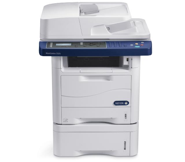
Xerox WorkCentre 3325DNI
Рейтинг


 Снят с производства
Тип устройства
МФУ
Технология печати
лазерная
Макс. формат
A4
Число страниц в месяц
80000
Скорость печати
A4
35
Цветность печати
черно-белая
Общие характеристики |
|
|---|---|
Сканер |
|
Печать фотографий |
|
Факс |
|
Телефон |
|
Копир |
|
Макс. формат |
A4 |
Тип устройства |
МФУ |
Число страниц в месяц |
80 000 |
Область применения |
средний офис |
Размещение |
настольный |
Цветность печати |
|
Технология печати |
лазерная |
Тип |
лазерный/светодиодный |
Принтер |
|
Пигментные чернила |
|
Двусторонняя печать |
|
Система непрерывной подачи чернил |
|
Прямая печать |
|
Печать без полей |
|
Время разогрева |
35 |
Макс, разрешение для ч/б печати |
|
| По X | 1 200 |
| По Y | 1 200 |
Скорость ч/б печати |
|
| A4 | 35 |
Время выхода первого отпечатка |
|
| Ч/б | 6,5 |
Копир |
|
Макс, количество копий за цикл |
999 |
Шаг масштабирования |
0,01 |
Время выхода первой копии |
6,5 |
Значение масштаба |
|
| Минимальное | 0,25 |
| Максимальное | 4 |
Макс, разрешение (ч/б) |
|
| По X | 600 |
| По Y | 600 |
| По X | 300 |
| По Y | 300 |
Сканер |
|
Стандарт TWAIN |
|
Отправка изображения по e-mail |
|
Стандарт WIA |
|
Слайд-адаптер |
|
Оттенки серого |
256 |
Емкость устройства автоподачи оригиналов |
50 |
Глубина цвета |
24 бит |
Тип сканера |
планшетный/протяжный |
Устройство автоподачи оригиналов |
двустороннее |
Макс. формат оригинала |
A4 |
Макс, размер сканирования |
|
| По X | 216 |
| По Y | 356 |
Разрешение сканера |
|
| По Y (улучшенное) | 4 800 |
| По Х (улучшенное) | 4 800 |
| По Х | 600 |
Скорость сканирования |
|
| Ч/б | 24 |
| Цветн, | 8 |
Расходные материалы |
|
Ресурс ч/б картриджа/тонера |
5 000 |
Количество картриджей |
1 |
Печать на: |
|
| Глянцевой бумаге |
|
| Матовой бумаге |
|
| Фотобумаге |
|
| Конвертах |
|
| CD/DVD |
|
| Рулоне |
|
| Этикетках |
|
| Пленках |
|
| Карточках |
|
Плотность бумаги |
|
| Минимальная | 60 |
| Максимальная | 220 |
Факс |
|
Цветной |
|
PC Fax |
|
Макс, скорость передачи данных |
33,6 Кбит/с |
Телефон |
|
Проводная трубка |
|
Спикерфон |
|
Стандарт DECT |
|
Автоответчик |
|
Caller ID |
|
АОН |
|
Беспроводная трубка |
|
Языки управления |
|
| PCL 5e |
|
|
|
|
| PPDS |
|
| PostScript |
|
| PostScript 3 |
|
| PCL 6 |
|
| PostScript 2 |
|
| PCL 5c |
|
Лотки |
|
Емкость лотка ручной подачи |
50 |
Подача бумаги |
|
| Максимальная | 820 |
| Стандартная | 300 |
Вывод бумаги |
|
| Стандартный | 150 |
Финишер |
|
Сортер |
|
Сортировка со сдвигом |
|
Степлер |
|
Брошюровщик |
|
Электронная сортировка |
|
Интерфейсы |
|
Устройство для чтения карт памяти |
|
Wi-Fi |
|
Ethernet (RJ-45) |
|
USB |
|
FireWire (IEEE 1394) |
|
Wi-Fi 802.11n |
|
Bluetooth |
|
LPT |
|
AirPrint |
|
Инфракрасный порт |
|
RS-232 |
|
Веб-интерфейс |
|
Память/Процессор |
|
Емкость жесткого диска |
2 |
Макс, объем памяти |
768 |
Частота процессора |
600 |
Объем памяти |
256 |
Дополнительная информация |
|
Работа от аккумулятора |
|
Экран |
|
Поддержка ОС |
|
| Mac OS |
|
| Linux |
|
| Windows |
|
| DOS |
|
Потребляемая мощность |
|
| При работе | 600 |
| В режиме ожидания | 50 |
Уровень шума |
|
| При работе | 53 |
| В режиме ожидания | 26 |
Габариты |
|
Высота |
458 |
Ширина |
469 |
Глубина |
447 |
Вес |
16,6 |
Модули
Phaser 3320 Main
Tray 1
ADF 1
BYPASS TRAY
Optional Cassette Tray 2
WorkCentre 3325 Platen DADF
PANEL
WorkCentre 3315/3325 Middle Platen
WorkCentre 3315 ADF (1/2)
COVERS
Duplex assembly
WorkCentre 3315/3325 Main
Fuser
WorkCentre 3325 Platen
Phaser 3320 Covers
Phaser 3320 Control Panel
WorkCentre 3315 ADF (2/2)
PAPER FEED
WorkCentre 3325 Control Panel
Phaser 3320 Front Cover
WorkCentre 3325 Upper DADF
FRAME
DRIVE
WorkCentre 3315/3325 Middle Cover
FRAME L
Feed Drive
WorkCentre 3315/3325 Covers
WorkCentre 3325 Lower DADF
WorkCentre 3315 Platen
DUPLEX
WorkCentre 3325 DADF Platen
Rear Frame
Phaser 3320 Right Cover
WorkCentre 3315 Scanner and ADF
Детали ADF 1

| Деталь: | Main Board (Non-Wireless) |
| Парткод: | 140N63636 |

| Деталь: | LEFT COVER |
| Парткод: | 002N03055 |

| Деталь: | TOP COVER |
| Парткод: | 002N03056 |

| Деталь: | REAR COVER |
| Парткод: | 095N0041 5 |

| Деталь: | RIGHT COVER |
| Парткод: | 002N03057 |
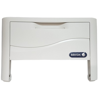
| Деталь: | FRONT COVER |
| Парткод: | 002N03058 |

| Деталь: | Duplex assembly |
| Парткод: | 022N02676 |

| Деталь: | Tray 1 |
| Парткод: | 050N00650 |

| Деталь: | Main Board (Wireless) |
| Парткод: | 140N63637 |

| Деталь: | Wireless Board |
| Парткод: | 140N63633 |

| Деталь: | Cassette (Tray 1) |
| Парткод: | 050N00650 |

| Деталь: | Cassette Pad RPR (Base Plate Pad) |
| Парткод: | 050N00646 |

| Деталь: | Retard Roller Cassette |
| Парткод: | 050N00649 |
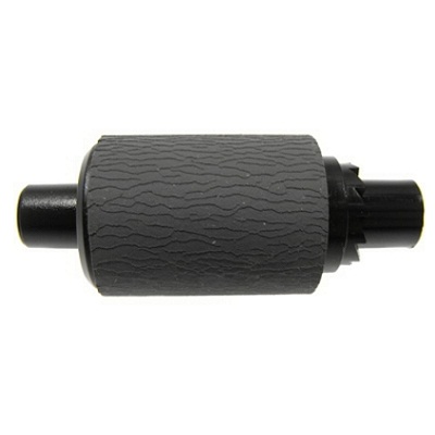
| Деталь: | Ролик захвата бумаги в автоподатчике документов, в сборе |
| Парткод: | 022N02373 |
| Цена: | 460 ₽ |
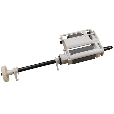
| Деталь: | Узел захвата бумаги из автоподатчика документов |
| Парткод: | 130N01533 |
| Цена: | 3 900 ₽ |
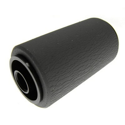
| Деталь: | Ролик подачи бумаги в автоподатчике документов, в сборе |
| Парткод: | 022N02190 |
| Цена: | 400 ₽ |

| Деталь: | Bypass Tray |
| Парткод: | 130N01676 |

| Деталь: | Bypass Tray Paper Empty Sensor |
| Парткод: | 130N01574 |

| Деталь: | Retard Roller Cassette (Retard Roller) (includes 15, 16) |
| Парткод: | 022N02677 |
| Цена: | 2 000 ₽ |

| Деталь: | Retard Shaft Holder |
| Парткод: | 006N01347 |

| Деталь: | Pick Up MP (Bypass Tray Pick Up Assembly) |
| Парткод: | 130N01675 |

| Деталь: | Optional Tray |
| Парткод: | 497N01412 |

| Деталь: | Pick Up Unit A/S Assy |
| Парткод: | 130N01674 |

| Деталь: | Drive Unit A/S Assy |
| Парткод: | 007N01666 |

| Деталь: | Electric clutch |
| Парткод: | 121N01219 |
| Цена: | 2 500 ₽ |

| Деталь: | Electric clutch |
| Парткод: | 121N01220 |
| Цена: | 1 100 ₽ |

| Деталь: | Main SCF PBA A/S Assy (Optional Tray Feeder Board) |
| Парткод: | 140N63640 |

| Деталь: | Left Cover CSP |
| Парткод: | 002N03061 |

| Деталь: | Right Cover CSP |
| Парткод: | 002N03062 |

| Деталь: | Top Dummy Cover CSP |
| Парткод: | 002N03060 |

| Деталь: | Front Dummy Cover CSP |
| Парткод: | 002N03063 |

| Деталь: | Cassette A/S Assy |
| Парткод: | 050N00647 |

| Деталь: | AS Unit Lift |
| Парткод: | 120N00537 |

| Деталь: | Unit Pick up Roller |
| Парткод: | 002N02232 |

| Деталь: | Lifting solenoid |
| Парткод: | 121N01160 |

| Деталь: | Кабель питания |
| Парткод: | 117N01769 |
| Цена: | 1 800 ₽ |
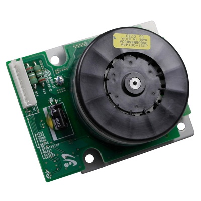
| Деталь: | Главный мотор |
| Парткод: | JC31-00144A |
| Цена: | 3 200 ₽ |

| Деталь: | Middle Platen 3315 |
| Парткод: | 090N00172 |

| Деталь: | Middle Platen 3325 |
| Парткод: | 090N00177 |

| Деталь: | Scan Drive ELA Unit (Scan Motor) |
| Парткод: | 007N01629 |

| Деталь: | Home Position Sensor |
| Парткод: | 130N01601 |

| Деталь: | Contact Image Sensor (WorkCentre 3315) |
| Парткод: | 130N01667 |
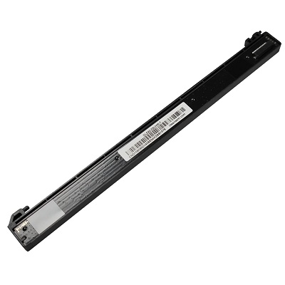
| Деталь: | Contact Image Sensor (WorkCentre 3325) |
| Парткод: | 130N01679 |
| Цена: | 7 100 ₽ |

| Деталь: | Gear Timing Belt |
| Парткод: | 007N01704 |
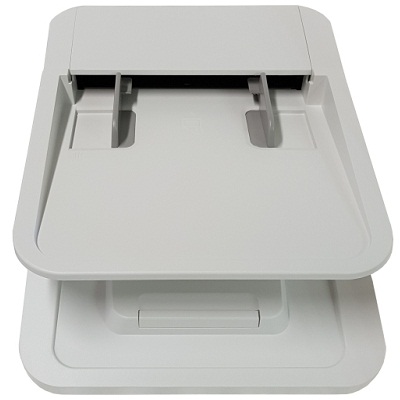
| Деталь: | ADF |
| Парткод: | 022N02680 |
| Цена: | 8 400 ₽ |

| Деталь: | ADF MOTOR |
| Парткод: | 127N07781 |

| Деталь: | Pick Up Housing CSP (with 1,2,7) |
| Парткод: | 130N01672 |

| Деталь: | Gear Separate Roller CSP |
| Парткод: | 130N01673 |
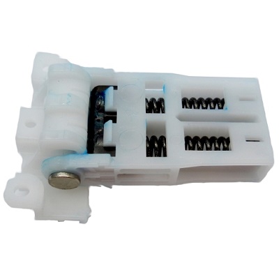
| Деталь: | Петля модуля сканера |
| Парткод: | 003N01018 |
| Цена: | 1 100 ₽ |
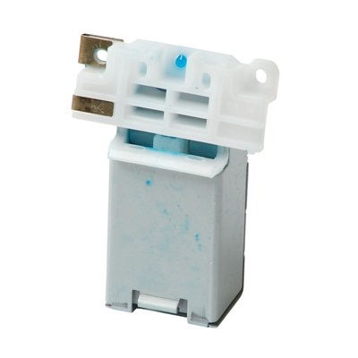
| Деталь: | Left ADF Hinge |
| Парткод: | 003N01031 |
| Цена: | 1 200 ₽ |

| Деталь: | Duplex assembly |
| Парткод: | 022N02676 |

| Деталь: | WorkCentre 3315, Main Board |
| Парткод: | 140N63643 |

| Деталь: | WorkCentre 3325DNI, Main Board |
| Парткод: | 140N63635 |
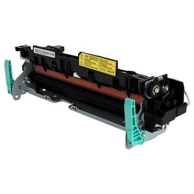
| Деталь: | Fuser (220V) |
| Парткод: | 126N00411 |
| Цена: | 12 500 ₽ |

| Деталь: | CASSETTE |
| Парткод: | 050N00650 |

| Деталь: | Phaser 3320, Main Board |
| Парткод: | 140N63636 |

| Деталь: | PBA SUB-Modem (Fax Board) |
| Парткод: | 140N63646 |

| Деталь: | Modem Cable (Modem Interface Cable) |
| Парткод: | 117N01937 |

| Деталь: | Fuser (110V) |
| Парткод: | 126N00410 |

| Деталь: | Fuser (110V) |
| Парткод: | 126N00410 |

| Деталь: | Fuser (220V) |
| Парткод: | 126N00411 |
| Цена: | 12 500 ₽ |

| Деталь: | NTC Assy Thermistor |
| Парткод: | 130N01668 |
| Цена: | 2 800 ₽ |

| Деталь: | PLATEN |
| Парткод: | 090N00178 |

| Деталь: | Lower Platen |
| Парткод: | 090N00176 |

| Деталь: | Upper Platen |
| Парткод: | 090N00175 |

| Деталь: | A4 Middle Platen |
| Парткод: | 090N00177 |

| Деталь: | LEFT COVER |
| Парткод: | 002N03055 |

| Деталь: | TOP COVER ASSEMBLY |
| Парткод: | 002N03056 |

| Деталь: | Rear door |
| Парткод: | 095N00415 |
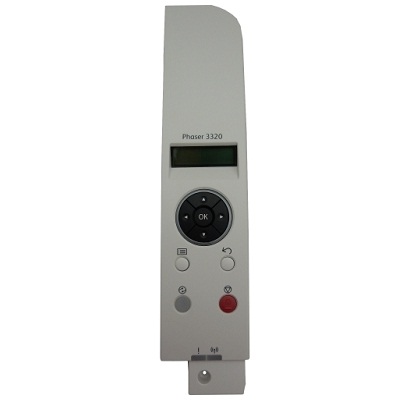
| Деталь: | Phaser 3320DNI Control Panel Cover |
| Парткод: | 101N01466 |

| Деталь: | Phaser 3320DNI Control Panel Board |
| Парткод: | 140N63639 |

| Деталь: | Phaser 3320DN Control Panel Cover |
| Парткод: | 101N01465 |

| Деталь: | Phaser 3320DN Control Panel Board |
| Парткод: | 140N63638 |
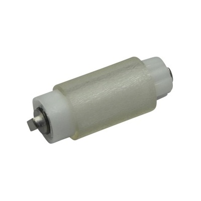
| Деталь: | Ролик отделения бумаги из основного лотка, в сборе |
| Парткод: | 050N00693 |
| Цена: | 2 500 ₽ |
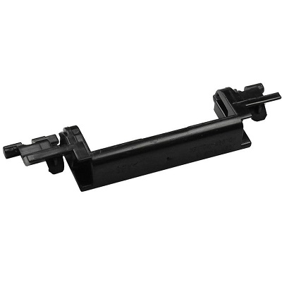
| Деталь: | Держатель ролика отделения бумаги из кассеты |
| Парткод: | JC61-04327A |
| Цена: | 280 ₽ |
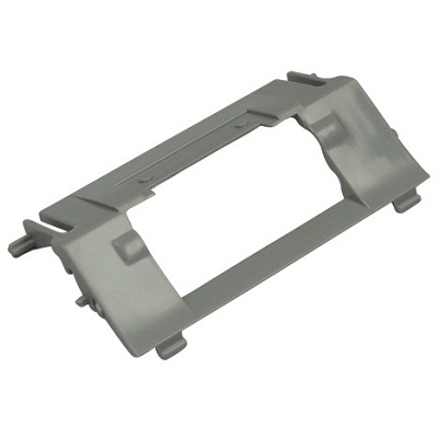
| Деталь: | Основание площадки отделения бумаги из кассеты |
| Парткод: | JC63-02917A |
| Цена: | 240 ₽ |
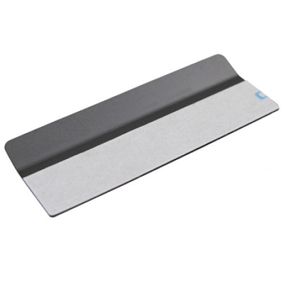
| Деталь: | Скоба накладки тормозной площадки из кассеты |
| Парткод: | JC63-02933A |
| Цена: | 260 ₽ |

| Деталь: | Накладка площадки отделения бумаги из кассеты |
| Парткод: | JC63-02984A |
| Цена: | 260 ₽ |
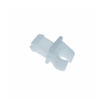
| Деталь: | Подшипник вала подачи бумаги |
| Парткод: | JC72-00382B |
| Цена: | 260 ₽ |
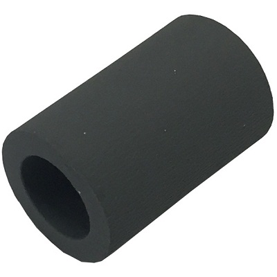
| Деталь: | Резиновый элемент на ролик отделения бумаги в лотке ручной подачи* |
| Парткод: | JC73-00328A |
| Цена: | 430 ₽ |
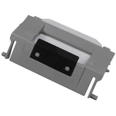
| Деталь: | Основание площадки отделения бумаги из кассеты, в сборе |
| Парткод: | JC90-01279B |
| Цена: | 220 ₽ |

| Деталь: | Control Panel Cover (Outside) WorkCentre 3325DN Control Panel Cover |
| Парткод: | 101N01469 |

| Деталь: | 110V (Inside) |
| Парткод: | 101N01468 |

| Деталь: | 220V (Inside) WorkCentre 3325DNI Control Panel Cover |
| Парткод: | 002N03065 |

| Деталь: | 110V (Inside) |
| Парткод: | 101N01463 |

| Деталь: | 220V (Inside) |
| Парткод: | 101N01464 |

| Деталь: | LCD |
| Парткод: | 123N00264 |

| Деталь: | Control panel board |
| Парткод: | 140N63634 |

| Деталь: | FRONT COVER |
| Парткод: | 002N03058 |
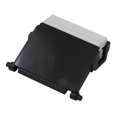
| Деталь: | Rubber DADF MEA Unit (Separator Pad) |
| Парткод: | 003N01042 |
| Цена: | 1 200 ₽ |

| Деталь: | Phaser 3320/WorkCentre 3315 LVPS (110V) |
| Парткод: | 105N02245 |

| Деталь: | Phaser 3320/WorkCentre 3315 LVPS(220V) |
| Парткод: | 105N02246 |
| Цена: | 11 300 ₽ |

| Деталь: | WorkCentre 3325 LVPS (110V) |
| Парткод: | 105N02247 |

| Деталь: | WorkCentre 3325 LVPS(220V) |
| Парткод: | 105N02249 |
| Цена: | 13 600 ₽ |

| Деталь: | Electric Clutch (Bypass Tray Clutch) |
| Парткод: | 1 21 N01219 |

| Деталь: | MP (Bypass Tray) |
| Парткод: | 130N01676 |

| Деталь: | Fuser (110V), shown in Parts List 3.3 Fuser |
| Парткод: | 126N00410 |

| Деталь: | Fuser (220V), shown in Parts List 3.3 Fuser |
| Парткод: | 126N00411 |
| Цена: | 12 500 ₽ |
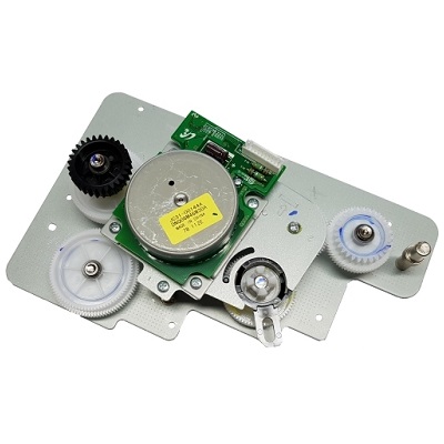
| Деталь: | DRIVE |
| Парткод: | 007N01711 |

| Деталь: | Feed drive |
| Парткод: | 022N02679 |

| Деталь: | PHOTO INTERRUPTER |
| Парткод: | 130N01574 |

| Деталь: | Thermistor NTC Assy, shown in Parts List 3.3 Fuser |
| Парткод: | 130N01668 |
| Цена: | 2 800 ₽ |

| Деталь: | TS Spring |
| Парткод: | 009N01653 |

| Деталь: | LVPS Fan (110V printers only) |
| Парткод: | 127N07782 |

| Деталь: | HVPS |
| Парткод: | 105N02248 |
| Цена: | 7 200 ₽ |

| Деталь: | Electric Clutch (Registration Clutch) |
| Парткод: | 1 21 N01219 |

| Деталь: | Electric Clutch (Pick Up Clutch) |
| Парткод: | 1 21 N01220 |

| Деталь: | Exit Sensor Holder |
| Парткод: | 130N01669 |

| Деталь: | 23/23 RDCN Gear |
| Парткод: | 007N01706 |

| Деталь: | Bar Coupling Lever |
| Парткод: | 005N01146 |

| Деталь: | 96 Idle Exit Gear |
| Парткод: | 007N01707 |

| Деталь: | 29 Idle Feed Gear |
| Парткод: | 007N01708 |

| Деталь: | 20 Feed Gear |
| Парткод: | 022N02672 |
| Цена: | 260 ₽ |
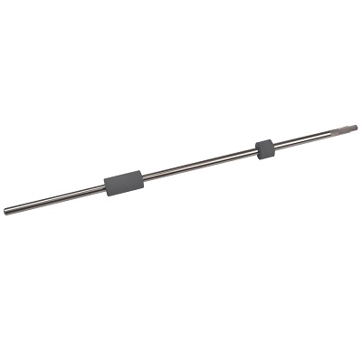
| Деталь: | FEED ROLLER |
| Парткод: | 022N02673 |
| Цена: | 1 100 ₽ |
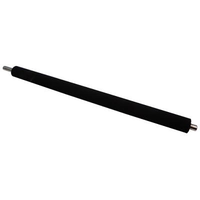
| Деталь: | TRANSFER ROLLER |
| Парткод: | 022N02674 |
| Цена: | 1 800 ₽ |
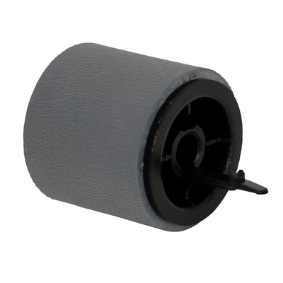
| Деталь: | Pick Up Roller (with 118 and 119) |
| Парткод: | 130N01677 |
| Цена: | 170 ₽ |

| Деталь: | Pick Up Housing |
| Парткод: | 130N01670 |
| Цена: | 300 ₽ |

| Деталь: | PICK UP RUBBER |
| Парткод: | 130N01671 |
| Цена: | 750 ₽ |

| Деталь: | Exit Roller Frame (with 121 and 122) |
| Парткод: | 022N02678 |

| Деталь: | CRUM Lower Holder |
| Парткод: | 019N01076 |

| Деталь: | CRUM Upper Holder |
| Парткод: | 019N01077 |

| Деталь: | CRUM Terminal |
| Парткод: | 116N00276 |

| Деталь: | 19 DR Swing Gear |
| Парткод: | 007N01705 |

| Деталь: | LSU (Laser Unit) |
| Парткод: | 130N01678 |
| Цена: | 12 200 ₽ |

| Деталь: | Duplex assembly |
| Парткод: | 022N02676 |

| Деталь: | BLDC Motor (Main Drive Motor) |
| Парткод: | 127N07780 |

| Деталь: | Middle Cover |
| Парткод: | 095N00416 |

| Деталь: | SPEAKER |
| Парткод: | 130N01532 |

| Деталь: | Wireless Board |
| Парткод: | 140N63633 |

| Деталь: | PBA SUB-MODEM |
| Парткод: | 140N63646 |

| Деталь: | Прижимной вал |
| Парткод: | 022N02357 |

| Деталь: | Прижимной вал |
| Парткод: | 022N02358 |

| Деталь: | Термостат |
| Парткод: | 4712-001091 |
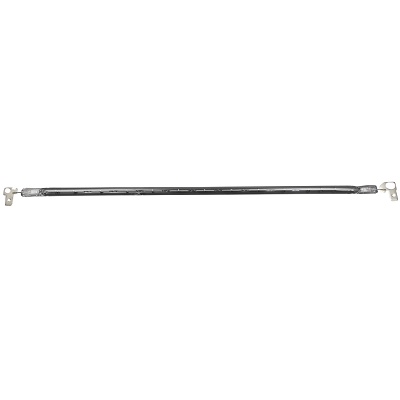
| Деталь: | Лампа нагрева тефлонового вала |
| Парткод: | 4713-001565 |
| Цена: | 1 200 ₽ |

| Деталь: | Пружина пальца отделения |
| Парткод: | 6107-002817 |
| Цена: | 1 200 ₽ |
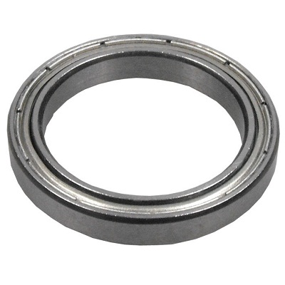
| Деталь: | Шариковый подшипник тефлонового вала |
| Парткод: | 6601-001725 |
| Цена: | 1 000 ₽ |

| Деталь: | Подшипник прижимного вала |
| Парткод: | JC61-01960A |

| Деталь: | Палец отделения бумаги от тефлонового вала |
| Парткод: | JC61-02154A |
| Цена: | 500 ₽ |
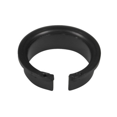
| Деталь: | Втулка подшипника тефлонового вала |
| Парткод: | JC61-04093A |
| Цена: | 230 ₽ |

| Деталь: | Подшипник прижимного вала |
| Парткод: | JC61-04095A |
| Цена: | 500 ₽ |

| Деталь: | Шестерня привода тефлонового вала |
| Парткод: | JC66-02775A |
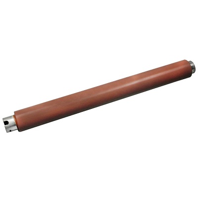
| Деталь: | Тефлоновый вал |
| Парткод: | JC66-02846A |
| Цена: | 2 400 ₽ |

| Деталь: | Middle Cover |
| Парткод: | 095N00413 |

| Деталь: | REAR COVER |
| Парткод: | 095N00415 |

| Деталь: | RIGHT COVER |
| Парткод: | 095N00417 |

| Деталь: | Sheet-Output_5V Note: Order this adhesive-backed sheet to cover the 5V input when replacing the Right Cover. |
| Парткод: | 019N01079 |

| Деталь: | LEFT COVER |
| Парткод: | 095N00418 |

| Деталь: | FRONT COVER |
| Парткод: | 095N00419 |

| Деталь: | PLATEN |
| Парткод: | 090N00173 |

| Деталь: | Upper Platen |
| Парткод: | 090N00171 |

| Деталь: | Lower Platen |
| Парткод: | 090N00174 |

| Деталь: | A4 Middle Platen |
| Парткод: | 090N00172 |

| Деталь: | ADF PBA (ADF Board) |
| Парткод: | 140N63641 |

| Деталь: | Подшипник |
| Парткод: | JC61-00424A |
| Цена: | 500 ₽ |

| Деталь: | Втулка колебательного узла |
| Парткод: | JC61-02220A |
| Цена: | 1 200 ₽ |

| Деталь: | Держатель вала регистрации |
| Парткод: | JC61-02233A |
| Цена: | 260 ₽ |

| Деталь: | Шестерня привода двухсторонней печати |
| Парткод: | JC66-01651A |
| Цена: | 260 ₽ |
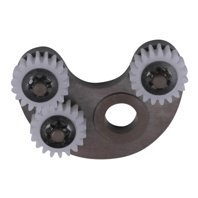
| Деталь: | Колебательный узел двухсторонней печати, в сборе |
| Парткод: | JC96-04732A |
| Цена: | 1 300 ₽ |
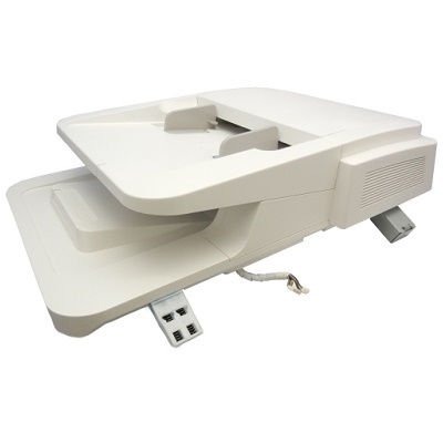
| Деталь: | DADF |
| Парткод: | 022N02682 |
| Цена: | 17 900 ₽ |
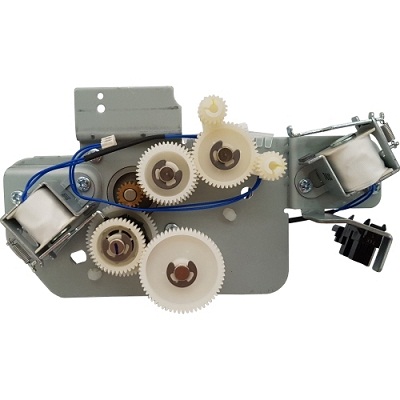
| Деталь: | DADF Drive |
| Парткод: | 007N01712 |

| Деталь: | DADF PBA (DADF Board) |
| Парткод: | 140N63301 |
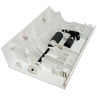
| Деталь: | DADF Open Cover |
| Парткод: | 002N03064 |
Коды ошибок
01-100
01-110
03-410
03-420
03-450
03-600
03-602
03-800
04-500
05-100
05-600
05-900
05-920
06-100
06-200
07-110
07-130
07-210
07-220
07-230
07-500
07-530
08-100
08-500
08-600
08-610
08-700
09-100
09-350
09-450
09-550
09-800, 09-820
10-100, 10-200
10-300
14-100
17-100
17-200
17-562, 17-563
17-700
17-710
17-800
17-810
17-900
20-100
Описание
| Error code: | 01-100 |
| Display: | Door is open Close it |
| Description: | Door Open RAP 01-100 The machine has detected that the right cover assembly is open. When the cover is open, there is no +24V supply to the motors or the HVPS. |
| Causes: | The machine has detected that the front door is open. When the front door is open there is no +24V supply to the motors or the HVPS. |
| Remedy: | 1. Switch off the machine, then switch on the machine. 2. Check that the interlock switch actuator on the right cover assembly, PL 7.30 Item 1 is not missing or damaged. 3. Check that the right cover assembly closes correctly. 4. Enter dC330 code 01-100. Check the side cover interlock switch assembly (S01-100), PL 4.15 Item 12. 5. Check the wiring between the side cover interlock switch and CN8 on the Main PWB. If necessary, install a side cover interlock switch assembly, PL 4.15 Item 12. 6. If necessary, install a new main PWB, PL 1.10 Item 1. |
| Error code: | 01-110 |
| Display: | Rear Door Open |
| Description: | Fuser Door Open |
| Causes: | The machine has detected that the fuser door is open. When the front door is open there is no +24V supply to the motors or the HVPS. |
| Remedy: | 1. Switch off the machine, then switch on the machine. 2. Open the rear door, then the fuser door. 3. Check that the interlock switch actuator on the fuser door is not missing or damaged. If necessary, install a new fuser door. 4. Check that the fuser door assembly closes correctly. 5. If necessary, install a new HVPS. NOTE: The fuser door interlock switch is mounted on the HVPS. |
| Error code: | 03-410 |
| Display: | Load A4 in Tray 1 or Paper mismatch in Tray 1 |
| Description: | Paper Color mismatch. Paper Type mismatch. Paper Size mismatch. If printing from PC, ensure print driver and tray guide settings match. Verify tray guide settings. |
| Causes: | • Main Board (Phaser 3320) (WorkCentre 3315/3325) |
| Remedy: | • Load the correct media in the source tray. • Check paper settings for the affected tray and print driver. • Check tray guide settings. • If problem persists use the following procedure. 1. Check the Feed Sensor and Paper Empty Actuator are installed correctly. Does the error persist? Go to step 2. Complete. 2. Replace the Main Board. Complete. |
| Error code: | 03-420 |
| Display: | Load A4 In Tray2 or Paper mismatch Tray 2 |
| Description: | Paper Color mismatch. Paper Type mismatch. Paper Size mismatch. If printing from PC, ensure print driver and tray guide settings match. Verify tray guide settings. |
| Causes: | • Main Board (Phaser 3320) (WorkCentre 3315/3325) |
| Remedy: | • Load the correct media in the source tray. • Check paper settings for the affected tray and print driver. • Check tray guide settings. • If problem persists use the following procedure. 1. Check the Feed Sensor and Paper Empty Actuator are installed correctly. Does the error persist? Go to step 2. Complete. 2. Replace the Main Board. Complete. |
| Error code: | 03-450 |
| Display: | Load A4 In Bypass or Paper mismatch Tray 1 Load [A4] [Plain] |
| Description: | Bypass Tray Paper Information Mismatch |
| Causes: | The machine has detected a bypass tray paper colour, type or size mismatch during a print job. |
| Remedy: | 1. If the fault is present when printing, check that the print driver and machine tray information are correct. 2. Go to GP 4 System Administration Tools. Check that the relevant tray paper type, colour and size settings are correct. |
| Error code: | 03-600 |
| Display: | Memory Failure |
| Description: | Memory Failure RAP 03-600 The machine has detected a memory access failure |
| Causes: | The machine has detected a memory access failure. |
| Remedy: | 1. Switch off the machine, then switch on the machine. 2. Remove, then reinstall the memory DIMM, PL 1.10 Item 22. 3. Install new components as necessary: • Memory DIMM, PL 1.10 Item 22. • Main PWB, PL 1.10 Item 1. |
| Error code: | 03-602 |
| Display: | Memory Full Fax memory is full. |
| Description: | Hard Drive/ Internal Drive Failure, not running properly. Either delete unnecessary documents, retransmit after more memory becomes available, or split the transmission into more than one operation. If the error persists, replace the Main Board. |
| Causes: | • Memory • Main Board (Phaser 3320) (WorkCentre 3315/3325) |
| Remedy: | • Remove and reseat memory DIMMs. • Increase system memory. • Delete unnecessary files or split the Fax job into smaller transmissions. • If problem persists use the following procedure. 1. Cycle system power. Does the error persist? Go to step 2. Complete. 2. Reseat memory DIMM on the Main Board. Does the error persist? Replace the Main Board. Complete. |
| Error code: | 03-800 |
| Display: | Check Internal Drive |
| Description: | Check HDD 03-800 The machine has detected a fault with the hard disk drive (HDD). |
| Causes: | The machine has detected a fault with the hard disk drive (HDD). |
| Remedy: | 1. Switch off the machine, then switch on the machine. 2. Check that the HDD PWB, PL 1.10 Item 17 is securely connected to CN20 on the Main PWB. 3. Check that the HDD ribbon cable, PL 1.10 Item 18 is securely connected to the HDD PWB and the HDD. 4. Install new components as necessary: • HDD harness, PL 1.10 Item 18. • HDD PWB, PL 1.10 Item 17. • HDD, PL 1.10 Item 11. • Main PWB, PL 1.10 Item 1. |
| Error code: | 04-500 |
| Display: | Motor Error Turn off then on |
| Description: | Main Motor Locked RAP 04-500 The machine has detected that the main BLDC motor is not being controlled. |
| Causes: | • Main Drive Motor • Main Board Phaser 3320 WorkCentre 3315/3325 |
| Remedy: | 1. Switch off the machine, then switch on the machine. 2. Remove the toner module, PL 9.10 Item 2, then the xerographic module, PL 9.10 Item 1. Enter dC330 code 04-100. Check that the main BLDC motor (MOT04-100), PL 4.20 Item 2 runs. 3. Check the wiring between the main BLDC motor and CN9 on the Main PWB. 4. If necessary, install new components: • Main BLDC motor, PL 4.20 Item 2. • Main PWB, PL 1.10 Item 1. |
| Error code: | 05-100 |
| Display: | Original Paper Jam Paper jam inside of Doc Feeder. |
| Description: | DADF Jam 1 RAP 05-100 The lead edge or trail edge of the document failed to actuate or deactuate the scan sensor within the correct time. |
| Causes: | The lead edge of the document failed to actuate the scan sensor within the correct time after registration solenoid actuation. |
| Remedy: | 1. Open the DADF top cover assembly, PL 5.15 Item 11. Remove all jammed paper. 2. Check the document path for damage or obstructions. 3. Check that the following components are clean and rotate freely. • Registration roll, PL 5.15 Item 21. • Registration roll idlers, PL 5.15 Item 28. 4. Remove the DADF left guide, PL 5.20 Item 9. 5. Check that the scan sensor actuator, PL 5.25 Item 28 moves freely and is not damaged. 6. Enter dC330 code 05-140. Check the scan sensor (Q05-140). NOTE: The scan sensor is mounted on the DADF PWB, PL 5.20 Item 6. 7. Remove the DADF rear cover, PL 5.10 Item 4. Enter dC330 code 05-200. Check that the DADF scan motor, PL 5.25 Item 12 runs and drives the scan roll, PL 5.25 Item 23. 8. Close the DADF top cover assembly. While the DADF scan motor runs, stack the code 05-310 to energize the registration clutch (CL05-310). Check that the registration roll, PL 5.15 Item 21 rotates. 9. Check the wiring between the DADF scan motor and CN4 on the DADF PWB. 10. Check the wiring between the registration clutch, PL 5.25 Item 19 and CN6 on the DADF PWB. If necessary, install a new registration clutch, PL 5.25 Item 19. 11. If necessary, install new components: • DADF PWB, PL 5.20 Item 6. • DADF scan motor, PL 5.25 Item 12. • DADF scan motor assembly, PL 5.25 Item 10. • Document transport assembly, PL 5.10 Item 2. |
| Error code: | 05-600 |
| Display: | Original Paper Jam Paper jam inside of Doc Feeder. |
| Description: | DADF Jam 6 RAP 05-600 The machine has detected that a DADF sensor is actuated when the machine is switched on. |
| Causes: | The machine has detected that a DADF sensor is actuated when the machine is switched on. |
| Remedy: | 1. Open the DADF top cover assembly, PL 5.15 Item 11. Remove all jammed paper. 2. Raise the DADF input tray, PL 5.10 Item 5. Remove all jammed paper. 3. Check the document path for damage or obstructions. 4. Check that the following actuators move freely and are not damaged: • Document detect sensor actuator, PL 5.20 Item 17. • Paper width sensor actuator, PL 5.20 Item 17. • Paper length sensor actuator, PL 5.10 Item 14. • Registration sensor actuator, PL 5.15 Item 12. • Scan sensor actuator, PL 5.25 Item 28. • Gate sensor actuator, PL 5.10 Item 26. • Duplex sensor actuator, PL 5.25 Item 27. 5. Enter dC330. Check the following sensors. Install new components as necessary: • Code 05-100, document detect sensor (Q05-100), PL 5.20 Item 13. • Code 05-110, paper width sensor (Q05-110), PL 5.20 Item 13. • Code 05-120, paper length sensor (Q05-120), PL 5.10 Item 12. • Code 05-130, registration sensor (Q05-130), PL 5.15 Item 14. • Code 05-140, scan sensor (Q05-140). • Code 05-150, gate sensor (Q05-150), PL 5.10 Item 24. • Code 05-170, duplex sensor (Q05-170). NOTE: The scan sensor and duplex sensor are mounted on the DADF PWB, PL 5.20 Item 6. 6. Check the following wiring: • Between the document detect sensor, and CN4 on the DADF Sensor PWB. • Between the paper width sensor and CN4 on the DADF Sensor PWB. • Between the paper length sensor and CN3 on the DADF Sensor PWB. • Between the registration sensor and CN5 on the DADF Sensor PWB. • Between the gate sensor and CN2 on the DADF Sensor PWB. • Between CN1 on the DADF Sensor PWB and CN3 on the DADF PWB. 7. If necessary, install new components: • DADF PWB, PL 5.20 Item 6. • DADF sensor PWB, PL 5.20 Item 4. • Document transport assembly, PL 5.10 Item 2. |
| Error code: | 05-900 |
| Display: | Original Paper Jam Paper jam inside of Doc Feeder. |
| Description: | DADF Jam 0 RAP 05-900 The lead edge of the document failed to actuate the registration sensor within the correct time. |
| Causes: | The lead edge of the document failed to actuate the registration sensor within the correct time. |
| Remedy: | 1. Remove all jammed paper from the DADF input tray. 2. Open the DADF top cover assembly, PL 5.15 Item 11. Check the document path for damage or obstructions. 3. Check the feed roll assembly, PL 5.15 Item 5. If necessary, install a new feed roll assembly, PL 5.15 Item 5. 4. Check the retard pad, PL 5.20 Item 12. If necessary, install a new retard pad, PL 5.20 Item 12. 5. Check that the registration sensor actuator, PL 5.15 Item 12 moves freely and is not damaged. 6. Enter dC330 code 05-130. Check the registration sensor (Q05-130), PL 5.15 Item 14. 7. Check the wiring between the registration sensor and CN5 on the DADF Sensor PWB. If necessary, install a new registration sensor, PL 5.15 Item 14. 8. Check the wiring between CN1 on the DADF Sensor PWB and CN3 on the DADF PWB. 9. Enter dC330 code 05-200. Check that the DADF scan motor (MOT05-200), PL 5.25 Item 12 runs. 10. While the DADF scan runs, stack the code 05-300 to energize the pick up clutch (CL05- 300). Check that the feed roll, PL 5.15 Item 5 rotates. 11. Check the wiring between the pick up clutch and CN6 on the DADF PWB. If necessary, install a new pick up clutch, PL 5.15 Item 4. 12. Check the wiring between the DADF scan motor and CN4 on the DADF PWB. 13. If necessary, install new components: • DADF PWB, PL 5.20 Item 6. • DADF sensor PWB, PL 5.20 Item 4. • DADF scan motor, PL 5.25 Item 12. • DADF scan motor assembly, PL 5.25 Item 10. • Document transport assembly, PL 5.10 Item 2. |
| Error code: | 05-920 |
| Display: | Scanner door Open |
| Description: | DADF Door Open RAP 05-920 The machine has detected that the DADF door is open. |
| Causes: | The machine has detected that the DADF door is open. |
| Remedy: | 1. Open the DADF top cover assembly, PL 5.15 Item 11. Check that the DADF door open switch actuator on the top cover, PL 5.15 Item 22 is not missing or damaged. Install new components as necessary, PL 5.15. 2. Enter dC330 code 05-160. Check the DADF door open switch (S05-160), PL 5.25 Item 8. 3. Check the wiring between the DADF door open switch and CN6 on the DADF PWB. If necessary, install a new DADF door open switch, PL 5.25 Item 8. 4. If necessary, install new components: • DADF PWB, PL 5.20 Item 6. • Document transport assembly, PL 5.10 Item 2. |
| Error code: | 06-100 |
| Display: | LSU Motor Error |
| Description: | The LSU could not reach the READY state within the defined time. Turn the printer on and then off and then check to see if the error persists. |
| Causes: | • Laser Unit • Main Board (Phaser 3320) (WorkCentre 3315/3325) |
| Remedy: | • Turn the printer off and then on again. • If the problem persists continue troubleshooting. 1. Enter Service Mode and then select EDC Mode > DC Component Control > 110 LSU > LSU Motr 1R > On. Does the Laser Motor sound normal? Go to step 3. Remove the Right Cover (Phaser 3320: page 4-12; WorkCentre 3315/3325: page 4-17) and then go to step 2. 2. Remove the Top Cover, and check that the LSU harness is correctly connected to the LSU; Main Board P/J21 (WorkCentre 3315) or P/J17 (WorkCentre 3325), and P/J1 and 2 on the LSU. Reseat P/J21 or P/J17 on the Main Board. Inspect the LSU harness and repair if damaged. Does the error persist? Go to step 3. Complete. 3. Replace the LSU. Does the error persist? Replace the Main Board. Complete. |
| Error code: | 06-200 |
| Display: | LSU Hsync Error |
| Description: | The laser beam was not detected within the set time. Turn the printer on and then off and then check to see if the error persists. |
| Causes: | • Laser Unit • Main Board (Phaser 3320) (WorkCentre 3315/3325) |
| Remedy: | • Turn the printer off and then on again. • If the problem persists continue troubleshooting. 1. Enter Service Mode and then select EDC Mode > DC Component Control > 110 LSU > LSU Motr 1R > On. Does the Laser Motor sound normal? Go to step 3. Remove the Right Cover (Phaser 3320: page 4-12; WorkCentre 3315/3325: page 4-17) and then go to step 2. 2. Remove the Top Cover, and check that the LSU harness is correctly connected to the LSU; Main Board P/J21 (WorkCentre 3315) or P/J17 (WorkCentre 3325), and P/J1 and 2 on the LSU. Reseat P/J21 or P/J17 on the Main Board. Inspect the LSU harness and repair if damaged. Does the error persist? Go to step 3. Complete. 3. Replace the LSU. Does the error persist? Replace the Main Board. Complete. |
| Error code: | 07-110 |
| Display: | Tray 1 Empty |
| Description: | Paper Empty at Tray 1 RAP 07-110 The machine has detected that tray 1 is empty. |
| Causes: | The machine has detected that tray 1 is empty. |
| Remedy: | 1. Remove tray 1. Check that the tray 1 paper empty sensor actuator, PL 8.10 Item 4 moves freely and is not damaged. 2. Replace tray 1. Listen for the tray elevator to raise the knock-up plate. If the plate does not rise, check the wiring between the tray 1 elevator motor and CN19 on the Main PWB. If necessary, install new components: • Tray 1 elevator motor, PL 7.15 Item 8. • Tray feed assembly, PL 8.10 Item 1. 3. Enter dC330 code 07-110. Check the tray 1 paper empty sensor (S07-110), PL 8.10 Item 2. 4. Check the wiring between the tray 1 paper empty sensor and CN19 on the Main PWB. If necessary, install a new tray 1 paper empty sensor, PL 8.10 Item 2. 5. If necessary, install new components: • Tray 1 feed assembly, PL 8.10 Item 1. • Main PWB, PL 1.10 Item 1. |
| Error code: | 07-130 |
| Display: | Paper Jam in Tray 1 |
| Description: | Jam 0 From Tray 1 RAP 07-130 The lead edge of the paper failed to actuate the registration sensor within the correct time after paper was fed from tray 1. |
| Causes: | The lead edge of the paper failed to actuate the registration sensor within the correct time after paper was fed from tray 1. |
| Remedy: | 1. Pull out tray 1. Remove all jammed paper. 2. Check the paper path for damage or obstructions. 3. Check that the registration sensor actuator, PL 8.15 Item 4 moves freely and is not damaged. If necessary, install a new registration sensor actuator assembly, PL 8.15 Item 13. 4. Enter dC330 code 08-500. Check the registration sensor (Q08-500), PL 8.15 Item 8. 5. Check the wiring between the registration sensor and CN13 on the Main PWB. If necessary, install a new registration sensor, PL 8.15 Item 8. 6. Check that the feed sensor actuator, PL 8.15 Item 5 moves freely and is not damaged. If necessary, install a new feed sensor actuator assembly, PL 8.15 Item 14. 7. Enter dC330 code 08-100. Check the feed sensor (Q08-100), PL 8.15 Item 8. 8. Check the wiring between the feed sensor and CN13 on the Main PWB. If necessary, install a new feed sensor, PL 8.15 Item 8. 9. Enter dC330 code 04-100 to run the main BLDC motor. 10. While the main BLDC motor runs, stack the code 08-810 to energize the tray 1 pickup clutch (CL08-810). Check that the tray 1 feed roll, PL 8.10 Item 12 rotates. 11. Check the wiring between the tray 1 pickup clutch and CN13 on the Main PWB. Install new components as necessary, PL 4.20, PL 7.15 and PL 8.10. 12. While the main BLDC motor runs, stack the code 08-850 to energize the registration clutch (CL08-850). Check that the registration roll, PL 4.15 Item 1 rotates. 13. Check the wiring between the registration clutch and CN13 on the Main PWB. Install new components as necessary, PL 4.15 and PL 4.20. 14. Check that the following components are clean and rotate freely, install new components as necessary: • Tray 1 feed roll, PL 8.10 Item 12. • Tray 1 nudger roll, PL 8.10 Item 12. • Tray 1 retard roll, PL 7.15 Item 20. • Registration roll, PL 4.15 Item 1. • Registration roll idler, PL 4.15 Item 7. 15. If necessary, install new components: • Tray feed assembly, PL 8.10 Item 1. • Main PWB, PL 1.10 Item 1. |
| Error code: | 07-210 |
| Display: | Tray 2 Empty |
| Description: | Paper Empty at Tray 2 |
| Causes: | The machine has detected that tray 2 is empty. |
| Remedy: | 1. Pull out tray 2. Check that the paper empty actuator moves freely and is not damaged. 2. Enter dC330 code 07-230. Check the tray 2 paper empty sensor (S07-230) . 3. Check the wiring between the paper empty sensor and CN1 on the Tray 2 PWB. If necessary, install a new paper empty sensor . 4. Check the wiring between CN7 on the Tray PWB and CN33 and CN34 on the Main PWB. 5. If necessary: a. Install a new tray 2 PWB . b. Perform OF7 Main PWB Check RAP. |
| Error code: | 07-220 |
| Display: | Tray 2 is open. |
| Description: | Tray 2 is open. Close Tray 2 until it locks into place. |
| Causes: | • LVPS |
| Remedy: | • Close the door until it locks in to place. • If problem persists use the following procedure. 1. Reseat P/J18 on the Main Board and P/J4 on the LVPS. Does the error persist? Go to step 2. Complete. 2. Check the cover open switch for damage. Repair if damaged. Does the error persist? Go to step 3. Complete. 3. Replace the LVPS. Complete. |
| Error code: | 07-230 |
| Display: | Paper Jam in Tray 2 |
| Description: | Jam 0 From Tray 2 |
| Causes: | The lead edge of the paper failed to actuate the registration sensor within the correct time after paper was fed from tray 2. |
| Remedy: | 1. Pull out tray 1 and tray 2. Remove all jammed paper. 2. Check the paper path for damage or obstructions. 3. Remove the pickup roll assembly . Check that the pickup roll is clean. If necessary, install a new pickup roll assembly . 4. Check the retard pad on tray 2. If necessary, install a new retard pad assembly . 5. Check that the following components are clean and rotate freely, install new components as necessary: • Registration roll . • Registration roll idler . 6. Check that the registration sensor actuator moves freely and is not damaged. If necessary, install a new registration sensor actuator . 7. Enter dC330 code 08-500. Check the registration sensor (Q08-500). If necessary, install a new HVPS . NOTE: The registration sensor is mounted on the HVPS. 8. Enter dC330 code 08-920 to run the tray 2 feed motor. 9. Check the wiring between the tray 2 feed motor and CN8 on the Tray 2 PWB. 10. While the tray 2 feed motor runs, stack the code 08-820 to energize the tray 2 pickup clutch (CL08-820). Check that the tray 2 pickup roll assembly and feed roll rotate. Install new components as necessary . 11. Check the wiring between the tray 2 pickup clutch and CN11 on the Tray 2 PWB. 12. Enter dC330 code 04-100 to run the main BLDC motor. 13. Check the wiring between the main BLDC motor and CN38 on the Main PWB. 14. While the main BLDC motor runs, stack the code 08-850 to energize the registration clutch (CL08-850). Check that the registration roll does not rotate. Install new components as necessary . 15. Check the wiring between the registration clutch and CN35 on the Main PWB. 16. If necessary: a. Install new components: • Front duplex guide assembly . • Tray 2 feed motor . • Tray 2 PWB . • Tray 2 assembly . b. Perform OF7 Main PWB Check RAP. |
| Error code: | 07-500 |
| Display: | Bypass Empty |
| Description: | Paper Empty at Bypass Tray RAP 07-500 The machine has detected a failure to feed from the bypass tray. |
| Causes: | The machine has detected a failure to feed from the bypass tray. |
| Remedy: | 1. Open the right cover assembly, PL 7.30 Item 1. Check that the paper feed area at the bypass tray is clean. 2. Check the operation of the bypass paper empty sensor actuator, PL 8.20 Item 26. 3. Enter dC330 code 07-510. Check the bypass paper empty sensor (S07-510), PL 8.20 Item 26. 4. Check the wiring between the bypass paper empty sensor and CN21 on the Main PWB. If necessary, install a new bypass paper empty sensor, PL 8.20 Item 26. 5. If necessary, install new components: • Paper transport assembly, PL 8.20 Item 1. • Main PWB, PL 1.10 Item 1. |
| Error code: | 07-530 |
| Display: | Paper Jam in Bypass |
| Description: | Jam 0 From the Bypass Tray RAP The feed sensor failed to actuate within the correct time after paper was fed from the bypass tray. |
| Causes: | The registration sensor failed to actuate within the correct time after paper was fed from the bypass tray. |
| Remedy: | 1. Switch off the machine, then switch on the machine. 2. Open the right cover assembly, PL 7.30 Item 1. Remove all jammed paper. 3. Check the paper path for damage or obstructions. 4. Check that the feed sensor actuator, PL 8.15 Item 5 moves freely and is not damaged. If necessary, install a new feed sensor actuator assembly, PL 8.15 Item 14. 5. Enter dC330 code 08-100. Check the feed sensor (Q08-100), PL 8.15 Item 8. 6. Check the wiring between the feed sensor and CN13 on the Main PWB. If necessary, install a new feed sensor, PL 8.15 Item 8. 7. Enter dC330 code 04-100 to run the main BLDC motor. 8. While the main BLDC motor runs, stack the code 08-800 to energize the bypass feed clutch (CL08-800). Check that the bypass tray feed roll, PL 8.20 Item 17 rotates. 9. Check the wiring between the bypass feed clutch, PL 8.20 Item 28 and CN21 on the Main PWB. Install new components as necessary, PL 8.20. 10. While the main BLDC motor runs, stack the code 08-850 to energize the registration clutch (CL08-850). Check that the registration roll, PL 4.15 Item 1 rotates. 11. Check the wiring between the registration clutch, PL 4.15 Item 4 and CN13 on the Main PWB. Install new components as necessary, PL 4.15. 12. Check that the following components are clean and rotate freely, install new components as necessary: • Bypass tray feed roll, PL 8.20 Item 17. • Registration roll, PL 4.15 Item 1. • Registration roll idler, PL 4.15 Item 7. 13. If necessary, install new components: • Paper transport assembly, PL 8.20 Item 1. • Main PWB, PL 1.10 Item 1. |
| Error code: | 08-100 |
| Display: | Jam inside machine |
| Description: | Wait Sensor Jam Entry RAP 08-100 The lead edge of the paper failed to actuate the wait sensor within the correct time from feed sensor 1. |
| Causes: | The lead edge of the document failed to actuate the fuser exit sensor within the correct time after registration. |
| Remedy: | Identify the speed of the machine, refer to SCP 7 Machine features. Perform one of the steps that follow: • If the speed of the machine is 35-55 ppm, go to 08-100A Wait Sensor RAP (35-55 ppm) • If the speed of the machine is 65-90 ppm, go to 08-100B Wait Sensor RAP (65-90 ppm). |
| Error code: | 08-500 |
| Display: | Jam in exit area |
| Description: | Jam 2 RAP 08-500 The trail edge of the document failed to actuate the exit sensor within the correct time after registration. |
| Causes: | The trail edge of the document failed to deactuate the exit sensor within the correct time after registration. |
| Remedy: | 1. Open the right cover assembly, PL 7.30 Item 1. Remove all jammed paper. 2. Check the paper path for damage or obstructions. 3. Remove the fuser, PL 10.10 Item 4. Check that the exit sensor actuator, PL 10.25 Item 12 moves freely and is not damaged. If necessary, install a new exit sensor actuator, PL 10.25 Item 12. 4. Enter dC330 code 08-600. Check the exit sensor (Q08-600), PL 10.15 Item 2. 5. Check the wiring between the exit sensor and CN6 on the Main PWB. If necessary, install a new exit sensor, PL 10.15 Item 2. 6. Enter dC330 code 10-400. Check that the fuser motor (MOT10-400), PL 10.20 Item 3, runs and drives the fuser rolls and transport roll, PL 10.15 Item 22. 7. Check the wiring between the fuser motor and CN12 on the Main PWB. Install new components as necessary, PL 10.15 and PL 10.25. 8. Enter dC330 code 04-200. Check that the exit motor (MOT04-200), PL 10.20 Item 2, runs and drives the upper exit roll, PL 10.15 Item 23. 9. Check the wiring between the exit motor and CN12 on the Main PWB. Install new components as necessary, PL 10.15 and PL 10.20. 10. Check that the following components are clean and rotate freely: • Upper exit roll, PL 10.15 Item 23. • Lower exit roll, PL 10.15 Item 14. • Transport roll, PL 10.15 Item 22. • Transport roll idlers, PL 10.15 Item 19. 11. Install new components as necessary: • Fuser, PL 10.25 Item 1. • Exit assembly, PL 10.15 Item 1. • Main PWB, PL 1.10 Item 1. |
| Error code: | 08-600 |
| Display: | Jam bottom of duplex |
| Description: | Duplex Jam 0 RAP 08-600 The lead edge of the document failed to actuate the feed sensor within the correct time. |
| Causes: | The lead edge of the document failed to actuate the duplex jam 1 sensor within the correct time. |
| Remedy: | 1. Open the right hand cover. Remove all jammed paper. 2. Check the paper path for damage or obstructions. 3. Check that the feed sensor actuator, PL 8.15 Item 5 moves freely and is not damaged. If necessary, install a new feed sensor actuator assembly, PL 8.15 Item 14. 4. Enter dC330 code 08-100. Check the feed sensor (Q08-100), PL 8.15 Item 8. 5. Check the wiring between the feed sensor and CN13 on the Main PWB. If necessary, install a new feed sensor, PL 8.15 Item 8. 6. Enter dC330 code 04-100 to run the main BLDC motor. 7. While the main BLDC motor runs, stack the code 08-850 to energize the registration clutch (CL08-850). Check that the registration roll, PL 4.15 Item 1 rotates. 8. Check the wiring between the registration clutch, PL 4.15 Item 4 and CN13 on the Main PWB. Install new components as necessary, PL 4.15. 9. Clean the registration roll, PL 4.15 Item 1 and the registration roll idler, PL 4.15 Item 7. Install new components as necessary. 10. If necessary, install a new main PWB, PL 1.10 Item 1. |
| Error code: | 08-610 |
| Display: | Jam top of duplex |
| Description: | Duplex Jam 1 RAP 08-610 The lead edge of the document failed to actuate the duplex jam 1 sensor within the correct time in reverse mode. |
| Causes: | The lead edge of the document failed to actuate the registration sensor after the duplex jam 1 sensor within the correct time. |
| Remedy: | 1. Open the right hand cover. Remove all jammed paper. 2. Unclip the duplex assembly, PL 7.30 Item 28. Check that the paper path is clear and not damaged. 3. Check that the duplex jam 1 sensor actuator, PL 7.30 Item 20 moves freely and is not damaged. 4. Enter dC330 code 08-700. Check the duplex jam 1 sensor (Q08-700), PL 7.30 Item 18. 5. Check the wiring between the duplex jam 1 sensor and CN25 on the Main PWB. If necessary, install a new duplex jam 1 sensor, PL 7.30 Item 18. 6. Enter dC330 code 04-300, then code 04-310. Check that the duplex motor (MOT04-300), PL 10.20 Item 2, runs in forward and reverse and drives the duplex roll, PL 10.15 Item 22. 7. Check the wiring between the duplex motor and CN12 on the Main PWB. Install new components as necessary, PL 10.15 and PL 10.20. 8. Enter dC330 code 08-870. Check that the duplex gate solenoid (SOL08-870), PL 10.15 Item 4 energises and lowers the duplex gate, PL 10.15 Item 15. 9. Check the duplex gate for damage. If necessary, install a new duplex gate, PL 10.15 Item 15. 10. Check the wiring between the duplex gate solenoid and CN6 on the Main PWB. If necessary, install a new duplex gate solenoid, PL 10.15 Item 4. 11. Check that the following components are clean and rotate freely: • Duplex roll, PL 10.15 Item 22. • Duplex roll idlers, PL 10.15 Item 9. 12. If necessary, install new components: • Exit assembly, PL 10.15 Item 1. • Right cover assembly, PL 7.30 Item 1. • Main PWB, PL 1.10 Item 1. |
| Error code: | 08-700 |
| Display: | Output Bin full. Remove Paper |
| Description: | Out Bin Full RAP 08-700 The machine has detected that the exit tray is full. |
| Causes: | The machine has detected that the exit tray is full. |
| Remedy: | 1. Remove all documents from the exit tray. Check that the out bin full sensor actuator, PL 10.15 Item 25 moves freely and is not damaged. 2. Enter dC330 code 08-720. Check the out bin full sensor (Q08-720), PL 10.15 Item 2. 3. Check the wiring between the out bin full sensor and CN6 on the Main PWB. If necessary, install a new out bin full sensor, PL 10.15 Item 2. 4. Enter dC330 code 04-200. Check that the exit motor (MOT04-200), PL 10.20 Item 2, runs and drives the upper exit roll, PL 10.15 Item 23. 5. Check the wiring between the exit motor and CN12 on the Main PWB. Install new components as necessary, PL 10.15 and PL 10.20. 6. If necessary, install new components: • Exit assembly, PL 10.15 Item 1. • Main PWB, PL 1.10 Item 1. |
| Error code: | 09-100 |
| Display: | Toner Low |
| Description: | Toner Low RAP 09-100 The machine has detected that the toner module is almost empty. |
| Causes: | The machine has detected that the print cartridge is almost empty. |
| Remedy: | 1. No immediate action is necessary. Ensure that a replacement toner module, PL 9.10 Item 2 is in stock. NOTE: The toner low message is based on a pixel count, not a signal from a sensor. It cannot be reset by shaking the toner module. |
| Error code: | 09-350 |
| Display: | Replace Print Cart. |
| Description: | Erase Lamp Failure RAP 09-350 The photoreceptor erase lamp has failed. |
| Causes: | The print cartridge is near the end of the design life. The design life is 10,000 print pages. |
| Remedy: | NOTE: The door interlock switch must be cheated when checking +24V components. Cheat the door interlock switch. Enter dC330 code 09-022, photoreceptor erase lamp. Press start.. Observe the erase lamp. All the LEDs of the erase lamp are lit. Y↓N→Some of the LEDs of the erase lamp are lit. Y↓N→Go to Flag 1. +24V is available at P/J17 pin 1 on the LVPS. Y↓N→Install a new LVPS and base module, PL 1.10 Item 3. Go to Flag 2. +24V is available at P/J41 pin 1. Y↓N→Go to Flag 1. Check the inline fuse. The fuse is good. Y↓N→Install a new fuse, GP 7, PL 1.10 Item 9. If the fuse blows again, go to 01G Fused Distribution Check. Go to: • Go to 01G +24V Distribution RAP. • 01B 0V Distribution RAP. Go to Flag 3. +13V is available at P/J5 pin 14. Y↓N→NOTE: To gain access to the erase lamp wiring, remove the main drive module, (35-55 ppm) PL 4.15 Item 1, (65-90 ppm) PL 4.10 Item 1. Check the wiring, GP 7, from the in-line fuse to P/J41, pin 2. The wiring is good. Y↓N→Repair the wiring. Perform the steps that follow: • Check that the connector PJ41 is located correctly in the IOT frame. • Install a new erase lamp, (35 ppm) PL 9.22 Item 1, (40-90 ppm) PL 9.20 Item 1. Perform OF7 IOT PWB Diagnostics RAP before a new IOT PWB is installed, PL 1.10 Item 2. Install a new erase lamp, (35 ppm) PL 9.22 Item 1, (40-90 ppm) PL 9.20 Item 1. The fault may be intermittent. Perform the steps that follow: • Check the wiring, GP 7 between P/J41 and P/J17 on the LVPS. • Ensure that the P/Js are correctly and securely connected. • Malfunction of the following associated circuits can cause 09-350 faults. – The inverter paper path and Inverter nip solenoid, go to 10-120, 10-121, 10-126 IOT Exit Sensor RAP. – The vacuum transport fan and Registration clutch, go to 10-101A, 10-102A, 10-103A Lead Edge Late to Fuser Exit Sensor RAP. |
| Error code: | 09-450 |
| Display: | Replace Print Cart. |
| Description: | Replace Drum |
| Causes: | The print cartridge has reached the end of the design life of 10,000 print pages. |
| Remedy: | 1. Install a new print cartridge . |
| Error code: | 09-550 |
| Display: | Print Cartridge not installed or Install Print Cart. |
| Description: | Print Cartridge is not installed. Remove and reseat the Print Cartridge. |
| Causes: | • Print Cartridge • HVPS |
| Remedy: | • Turn the printer off and then on again. • If the problem persists continue troubleshooting. 1. Reseat the Print Cartridge. Does the error persist? Go to step 2. Complete. 2. Clean the high voltage contacts on the Print Cartridge and frame. Does the error persist? Go to step 3. Complete. 3. Replace the Print Cartridge. Does the error persist? Go to step 4. Complete. 4. Check the high voltage contacts located in the frame behind the HVPS. Are the contacts installed correctly and is spring tension adequate? Replace the HVPS. Repair the contacts. |
| Error code: | 09-800, 09-820 |
| Display: | Invalid Print Cartridge or Invalid Print Cartridge. Install Xerox Print Cart. |
| Description: | The Print Cartridge is not for this printer. Ensure the Print Cartridge is the correct part. Replace with a Genuine Xerox Print Cartridge. |
| Causes: | • Print Cartridge |
| Remedy: | • Ensure the Print Cartridge is valid for this printer. • Reseat the Print Cartridge. • Turn the printer off and then on again. • If the problem persists continue troubleshooting. 1. Reseat the Print Cartridge and cycle the power. Does the error persist? Replace the Print Cartridge. Complete. 2. Clean the HV contacts on the Print Cartridge and frame. Does the error persist? Go to step 3. Complete. 3. Replace the Print Cartridge. Does the error persist? Go to step 4. Complete. 4. Check the HV contacts located in the frame behind the HVPS. Are the contacts installed correctly and is spring tension adequate? Replace the HVPS. Repair the contacts. |
| Error code: | 10-100, 10-200 |
| Display: | Open Fuser error Low Heat error |
| Description: | Open Fuser Error/Low Heat Error RAP 10-100 During normal operation, the temperature of the fuser has dropped below the operating level. 10-200 The fuser has failed to reach the correct operating temperature. |
| Causes: | 10-100 During normal operation, the temperature of the fuser has dropped below the operating level. 10-200 The fuser has failed to reach the correct operating temperature. |
| Remedy: | 1. Switch off the machine, then switch on the machine. 2. Enter dC330 code 10-100 to heat the fuser to 180 degrees. Enter codes 10-200 and 10- 210 to verify the condition of the thermistors. 3. Enter code 10-300 to check power supply unit 2. If necessary, install a new power supply unit 2, PL 1.10 Item 4. 4. Switch off the machine. Remove the fuser assembly. Check that the thermistors, PL 10.25 Item 9 are clean and in good contact with the fuser heat roller. Check the wiring to the thermistors. Install new components as necessary, PL 10.25. 5. Check for continuity between the two pins on the fuser assembly connector, PL 10.25 Item 8. NOTE: A cold fuser has a resistance of approximately 11.5 ohms (220V/240V) or 2 ohms (110V). 6. Check that there is continuity through the fuser heater and across the over temperature cut-out. 7. Check the wiring between the fuser connector, PL 4.15 Item 20 and CON3, CON8 and CON9 on Power Supply Unit 2. If necessary, install a new fuser connector. 8. Check the wiring between CON4 on Power Supply Unit 2 and CN7 on the Main PWB. 9. Install new components as necessary: • Fuser assembly, PL 10.25 Item 1. • Main PWB, PL 1.10 Item 1. • HVPS, PL 1.10 Item 2. |
| Error code: | 10-300 |
| Display: | Over Heat error |
| Description: | Over Heat Error RAP 10-300 The fuser temperature has risen above the normal level. Although the fuser unit can return to a normal operating temperature, the fuser may consequently be damaged. |
| Causes: | The fuser temperature has risen above the normal level. Although the fuser unit can return to a normal operating temperature, the fuser may consequently be damaged. |
| Remedy: | 1. Enter codes 10-200 and 10-210. Perform a fuser temperature check to verify the condition of the thermistors. 2. Switch off the machine. Remove the fuser assembly. Examine the fuser assembly for heat damage. Install new components as necessary, PL 10.25 and PL 10.26. 3. Check that the thermistors, PL 10.25 Item 9 are in good contact with the fuser heat roller and are clean. Check the wiring to the thermistors. Install new components as necessary, PL 10.25. 4. Check that there is continuity through the fuser heater and across the over temperature cut-out. If necessary, install a new thermostat assembly, PL 10.25 Item 2. 5. Check the wiring between the fuser connector, PL 4.15 Item 20 and CON3, CON8 and CON9 on Power Supply Unit 2. If necessary, install a new fuser connector. 6. Check the wiring between CON4 on Power Supply Unit 2 and CN7 on the Main PWB. 7. Check that the fuser fan is working. Go to the OF3 Air Systems RAP. 8. Install new components as necessary: • Power supply unit 2, PL 1.10 Item 4. • Main PWB, PL 1.10 Item 1. • HVPS, PL 1.10 Item 2. |
| Error code: | 14-100 |
| Display: | Scanner Lock |
| Description: | CCD Lock RAP 14-100 The machine has detected a mechanical fault with the CCD module. |
| Causes: | The machine has detected a mechanical fault with the CCD module. |
| Remedy: | 1. If necessary, remove the finisher, REP 12.1. Check that the scanner lock, PL 14.10 Item 20 is completely unlocked. 2. Remove the scanner top cover assembly, refer to REP 14.2. 3. Check that the CCD module, PL 14.10 Item 2 moves freely from left to right. 4. Check the wiring between the scanner drive motor, PL 14.10 Item 4 and CN2 on the Scanner PWB. 5. If necessary, install new components: • Scanner drive motor assembly, PL 14.10 Item 4. • Scanner PWB, PL 14.10 Item 15. • CCD module, PL 14.10 Item 2. • Scanner assembly, PL 14.10 Item 1. |
| Error code: | 17-100 |
| Display: | IP Conflict or Network Problem: IP Conflict. |
| Description: | Two devices are trying to use the same IP address. |
| Remedy: | 1. Check the TCP/IP Address stored in the printer’s NVM. Is the address correct for the printer? Advise the customer of the address conflict. Enter the correct IP address. |
| Error code: | 17-200 |
| Display: | Network Problem |
| Description: | Network cable is not connected |
| Causes: | • Main Board |
| Remedy: | • Check network and data configuration settings. • Turn the printer off and then on again. 1. Disconnect the printer and ping the printer’s IP address. Is the ping successful? Another device is using the IP address, assign a different one. Go to step 2. 2. Check the LAN connections. Is the connection secure? Go to step 3. Reseat the LAN connector. 3. Check the Network Configuration settings. Are the TCP/IP settings correct? Go to step 4. Correct printer settings. 4. Check server configuration. Is the server configured to accept incoming data? Go to step 5. Correct server settings. 5. Cycle printer power. Does the error persist? Replace the Main Board. Complete. |
| Error code: | 17-562, 17-563 |
| Display: | No LUI message required |
| Description: | Machine is unable to contact the remote Xerox SMart eSolutions Communication Server. Review SMart eSolutions settings. |
| Remedy: | • Check network and data configuration settings. • Turn the printer off and then on again. • If the problem persists continue troubleshooting 1. Verify the SMart eSolutions settings are correct. Complete. |
| Error code: | 17-700 |
| Display: | BOOTP problem |
| Description: | BOOPT error and Auto IP is working. Input new static IP address or correct the BOOTP server address. |
| Remedy: | • Turn the printer off and then on again. • If the problem persists continue troubleshooting. 1. Input a new static IP address or reset server settings. Complete. |
| Error code: | 17-710 |
| Display: | BOOTP problem |
| Description: | BOOPT error and Auto IP is not working. Input new static IP address or correct the BOOTP server address. |
| Remedy: | • Turn the printer off and then on again. • If the problem persists continue troubleshooting. 1. Input a new static IP address or reset server settings. Complete. |
| Error code: | 17-800 |
| Display: | DHCP problem |
| Description: | DHCP error and Auto IP is working. Input new static IP address or correct the DHCP server address. |
| Remedy: | • Turn the printer off and then on again. • If the problem persists continue troubleshooting. 1. Input a new static IP address or reset server settings. Complete. |
| Error code: | 17-810 |
| Display: | DHCP problem |
| Description: | DHCP error and Auto IP is not working. Input new static IP address or correct the DHCP server address. |
| Remedy: | • Turn the printer off and then on again. • If the problem persists continue troubleshooting. 1. Input a new static IP address or reset server settings. Complete. |
| Error code: | 17-900 |
| Display: | 802.1x Network Error |
| Description: | 802.1X Authentication Error |
| Causes: | The 802.1X authentication failed. |
| Remedy: | 1. Ensure that the 802.1X EAP type, username and password for the machine authentication switch and authentication server match. |
| Error code: | 20-100 |
| Display: | Fax Comm Error |
| Description: | A problem with the facsimile communications has occurred. Try resending the fax. |
| Causes: | • Fax Board • Main Board (Phaser 3320) (WorkCentre 3315/3325) |
| Remedy: | • Call the target Fax number from a telephone to confirm a Fax tone response. • Check Fax line condition and connection. • Turn the printer off and then on again. • Verify the Fax line is an ANALOG phone line • If the problem persists continue troubleshooting. 1. Cycle system power. Does the error persist? Go to step 2. Complete. 2. Check the Country setting. Is the Country setting correct? Go to step 3. Correct the Country setting. 3. Check Fax communications to a different machine. Does the error persist? Go to step 4. Complete. 4. Enter Service Diagnostics and print the Event Log. Is the target Fax causing the error? Check target Fax configuration. Go to step 5. 5. Check the Fax Send settings. Are the settings at their defaults? Go to step 6. Correct the Fax settings. 6. Reseat the Fax Board. Does the error persist? Replace the Fax Board. Complete. 7. Check the connection between P/J1 on the Fax and P/26 Main Controller Board. Are connections secure? Replace the Main Board. Reseat the connectors. |
